EP0919178B9 - Wasserenthärtungsvorrichtung mit einem Harzerschöpfungsdetektor und Waschmaschine mit einer solchen Vorrichtung - Google Patents
Wasserenthärtungsvorrichtung mit einem Harzerschöpfungsdetektor und Waschmaschine mit einer solchen Vorrichtung Download PDFInfo
- Publication number
- EP0919178B9 EP0919178B9 EP98122315A EP98122315A EP0919178B9 EP 0919178 B9 EP0919178 B9 EP 0919178B9 EP 98122315 A EP98122315 A EP 98122315A EP 98122315 A EP98122315 A EP 98122315A EP 0919178 B9 EP0919178 B9 EP 0919178B9
- Authority
- EP
- European Patent Office
- Prior art keywords
- resins
- space
- container
- sensor
- cage
- Prior art date
- Legal status (The legal status is an assumption and is not a legal conclusion. Google has not performed a legal analysis and makes no representation as to the accuracy of the status listed.)
- Expired - Lifetime
Links
- 239000011347 resin Substances 0.000 title claims description 125
- 229920005989 resin Polymers 0.000 title claims description 125
- XLYOFNOQVPJJNP-UHFFFAOYSA-N water Substances O XLYOFNOQVPJJNP-UHFFFAOYSA-N 0.000 title claims description 68
- 238000005406 washing Methods 0.000 title claims description 19
- 230000008929 regeneration Effects 0.000 claims description 17
- 238000011069 regeneration method Methods 0.000 claims description 17
- 150000003839 salts Chemical class 0.000 claims description 12
- 230000003287 optical effect Effects 0.000 claims description 11
- 238000000034 method Methods 0.000 claims description 10
- 238000001514 detection method Methods 0.000 claims description 7
- 230000011664 signaling Effects 0.000 claims description 5
- 238000007789 sealing Methods 0.000 claims description 4
- 238000003780 insertion Methods 0.000 claims description 3
- 230000037431 insertion Effects 0.000 claims description 3
- 238000004851 dishwashing Methods 0.000 claims description 2
- 230000001172 regenerating effect Effects 0.000 claims description 2
- 208000016253 exhaustion Diseases 0.000 description 25
- 230000007423 decrease Effects 0.000 description 6
- 239000000243 solution Substances 0.000 description 6
- BHPQYMZQTOCNFJ-UHFFFAOYSA-N Calcium cation Chemical compound [Ca+2] BHPQYMZQTOCNFJ-UHFFFAOYSA-N 0.000 description 5
- JLVVSXFLKOJNIY-UHFFFAOYSA-N Magnesium ion Chemical compound [Mg+2] JLVVSXFLKOJNIY-UHFFFAOYSA-N 0.000 description 5
- 238000003466 welding Methods 0.000 description 5
- 150000002500 ions Chemical class 0.000 description 3
- 239000000463 material Substances 0.000 description 3
- 229910001415 sodium ion Inorganic materials 0.000 description 3
- NFLLKCVHYJRNRH-UHFFFAOYSA-N 8-chloro-1,3-dimethyl-7H-purine-2,6-dione 2-(diphenylmethyl)oxy-N,N-dimethylethanamine Chemical compound O=C1N(C)C(=O)N(C)C2=C1NC(Cl)=N2.C=1C=CC=CC=1C(OCCN(C)C)C1=CC=CC=C1 NFLLKCVHYJRNRH-UHFFFAOYSA-N 0.000 description 2
- FAPWRFPIFSIZLT-UHFFFAOYSA-M Sodium chloride Chemical compound [Na+].[Cl-] FAPWRFPIFSIZLT-UHFFFAOYSA-M 0.000 description 2
- 239000012267 brine Substances 0.000 description 2
- 229910001424 calcium ion Inorganic materials 0.000 description 2
- 229910001425 magnesium ion Inorganic materials 0.000 description 2
- 238000004519 manufacturing process Methods 0.000 description 2
- HPALAKNZSZLMCH-UHFFFAOYSA-M sodium;chloride;hydrate Chemical compound O.[Na+].[Cl-] HPALAKNZSZLMCH-UHFFFAOYSA-M 0.000 description 2
- 230000006835 compression Effects 0.000 description 1
- 238000007906 compression Methods 0.000 description 1
- 238000010276 construction Methods 0.000 description 1
- 238000011157 data evaluation Methods 0.000 description 1
- 238000011038 discontinuous diafiltration by volume reduction Methods 0.000 description 1
- 238000010292 electrical insulation Methods 0.000 description 1
- 239000008233 hard water Substances 0.000 description 1
- 238000005342 ion exchange Methods 0.000 description 1
- 238000012544 monitoring process Methods 0.000 description 1
- 238000000465 moulding Methods 0.000 description 1
- 230000000704 physical effect Effects 0.000 description 1
- 230000010287 polarization Effects 0.000 description 1
- 239000012492 regenerant Substances 0.000 description 1
- 239000008237 rinsing water Substances 0.000 description 1
- 239000012266 salt solution Substances 0.000 description 1
- 239000011780 sodium chloride Substances 0.000 description 1
- 239000000126 substance Substances 0.000 description 1
Images

Classifications
-
- A—HUMAN NECESSITIES
- A47—FURNITURE; DOMESTIC ARTICLES OR APPLIANCES; COFFEE MILLS; SPICE MILLS; SUCTION CLEANERS IN GENERAL
- A47L—DOMESTIC WASHING OR CLEANING; SUCTION CLEANERS IN GENERAL
- A47L15/00—Washing or rinsing machines for crockery or tableware
- A47L15/42—Details
- A47L15/4229—Water softening arrangements
Definitions
- the present invention relates to a device for reducing water hardness (softener), suitable for the use in a household washing machine, in particularly a dishwasher, and to a control method to check the exhaustion degree of the water hardness reducing means.
- Calcareous scale deposits are caused by an extremely high quantity of calcium ions (Ca++) and magnesium ions (Mg++) contained in the washing water.
- Such a decalcifier exchanges both the calcium ions (Ca++) and magnesium ions (Mg++) contained in the water with sodium ions (Na+) contained in appropriate resins placed in the decalcifier.
- This drawback is prevented through a resins regeneration phase, which is obtained introducing a water-salt solution (NaCl) with the aim of regenerating the resins.
- This phase is generally executed for each wash cycle, for which a considerable quantity of salt has to be used, often introduced by the user; moreover, a higher water consumption is also determined.
- Said sensors are used to measure the water resistivity and, from the results obtained through an electronic system, the resins regeneration will either be activated or not
- This system requires that electrodes have to be dipped in the water and electrically supplied.
- Document DE 3039712 relates to a device for detecting the charged state of the ion exchange material of a water softening plant for dishwashing or washing machines operating on the expansion of a sphere positioned in the ion exchanger.
- Document DE 3533098 proposes to arrange sensors in the inlet and the outlet of a ion exchanger vessel, which sensors are sensitive to the regenerant.
- sensors are used electric conductivity meters, which influence a programmed control via electronic data evaluation equipment.
- the aim of the present invention is that of solving the above drawbacks and provide in particular a device for reducing water hardness (softener), which is suitable for the use in a household washing machine, in particular a dishwasher, wherein the detection of the exhaustion of the reducing means is realized in a simple, safe, cheaper and direct manner.
- softener water hardness
- the present invention is based on the acknowledgment that the resins used to reduce water hardness tend to change their volume as they become exhausted.
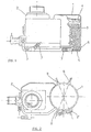
- a water softener is schematically represented, i.e. a device for reducing the water hardness according to the known state of the art
- number 1 indicates the resin container
- number 2 indicates a salt container for the regeneration of the resins
- the two containers are mechanically and hydraulically connected to each other and the water softener is manufactured in two parts, which are welded together through a hot-blade process, after having assembled the various components inside it
- number 3 indicates the water softening resins
- number 4 indicates an upper filter
- number 5 indicates a lower filter
- number 6 indicates the weld spot of both parts forming the water softener and number 7 various water pipelines.
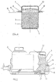
- Figures 2 and 3 show a plan view and a section view of a device for reducing the water hardness manufactured with a first type of sensor to detect the exhaustion of the resins used to reduce water hardness according to the present invention; in said figures 2 and 3 the same reference numbers as per Figure 1 are used to indicate the common elements.
- Numbers 8 and 8' indicate a couple of optical detectors arranged outside the body of the resins container 1, diametrically opposite to each other.
- Numbers 9 and 9' indicate a second couple of optical detectors arranged outside the body of the resins container 1, diametrically opposite to each other.
- the two diameters resulting from the two couples of sensors 8-8' and 9-9' have to be selected to have the largest area as possible covered by the sensors, compatibly with the overall dimensions of the decalcifier device.
- One sensor of said couples 8-8' and 9-9' is the light signal transmitter and the other sensor is the receiver.
- Said sensors 8-8', 9-9' are arranged outside and in contact with the resins container 1; their position and alignment for the correct operation is ensured by a structure 10, which is fitted and fastened outside the resin container 1 and carries the seats for said sensors.
- the line A indicates a first level reached by the resins in the container 1; the letter B indicates a second level reached by the resins in the container 1.
- Said first level A relates to the operating situation of the resins in their original status, i.e. before being used for the water softening, whereas said second level B represents the position of the resins after reaching a certain exhaustion degree.
- the couples of optical detectors 8-8' and 9-9' have the function of checking the variation of the resins height inside the container 1.
- the resins regeneration will be activated by said optical detectors conveniently arranged for such a height.
- the resins regeneration will only take place when required to avoid water and salt wastage.
- the material used for the resin container may be a clear one; otherwise the resin container may be manufactured with clear inserts, just in the area where said optical detectors are located.
- the resins level is not constant all along the perimeter, at least two couples of optical detectors are required, to carry out at least two detections and determine a level mean for the resins both in their natural status and exhaustion stage.
- Said space 12 has an open lower base, in correspondence with the joint line of the two parts of the container 11; a vertical wall of said space 12, indicated with number 13, realizes the outside wall of the container 11 and has slits interconnecting the container 11 with the space 12.
- Number 14 indicates a pressure sensor, for example of the piezoelectric type, arranged on the upper wall of the space 12 during the moulding of the container 11.
- Number 15 indicates a transducer being connected with the pressure sensor 14; number 16 indicates connections, which may be wires or Faston terminals; number 17 indicates a filter for the water entering the washing machine.
- the space 12 is completely filled with a certain amount of sample resins, indicated with number 18, being of the same type of the resins contained in the container 11.
- Resins 18 are introduced in the space 12 through its open part and maintained in position inside it through a portion of the filter 17, when the latter is welded to the above two parts forming the container.
- Welding is executed according to a so-called hot-blade welding process, i.e. both parts to be welded are melted together with a consequent height reduction of the vertical walls of the parts involved.
- the regeneration Upon reaching a certain threshold, for example 70%, referred to the pressure reached by the resins becoming exhausted, the regeneration is activated.
- Regeneration is activated under the control of an electronic control system, not shown in the figures as already generally known, which detects the signal transmitted by the pressure sensor 14 through the transducer 15.
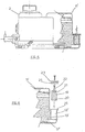
- a possible variant embodiment can be obtained using for example an interchangeable sensor, as represented in Figures 5 and 6, in order to solve possible operating irregularities.
- number 11' indicates a container for the resins used to reduce the water hardness
- number 12' indicates a space defined on a side of the container 11'.
- Number 17' indicates a lower filter of the container 11'; number 13' indicates a wall of the space 12', which is a portion of the external wall of the container 11', being provided with some slits interconnecting the container 11' with the space 12'. As it can be seen, the space 12' has both ends open.
- the lower end is closed by an extension of the filter 17', obtained as in the previous solution, during welding of both parts forming the container 11'.
- Number 19 indicates a cage whose shape and dimensions allow for its insertion inside the recess 12', as shown in Figure 5.
- Number 20 indicates a certain amount of sample resins in their natural granular status, i.e. similar to the resins housed in the container 11'.
- Number 21 indicates a pressure sensor with its relevant transducer 22 and electric wire or alternatively Faston terminal connections.
- Said cage 19 has an open side allowing a forced insertion of the pressure sensor 21 in a pre-existing hole on the upper side of the cage 19, also allowing to fill the cage with the resins 20.
- Said open side is then closed with a lid snap-fitted to the cage by means of small teeth, or welded in a known manner, for example by a hot-blade welding.
- the amount of resins filled in the cage will cause their compression when closing the lid, so that they exert a certain pressure on the sensor 21.
- the cage walls save for the wall whereon the pressure sensor is located, have slits for allowing the passage of water, but hinders the passage of the resins.
- Said cage 19 fitted with the pressure sensor and filled with resins is inserted in the space 12' formed on the body of the container 11'.
- the cage is kept inside the space 12' by a closure plug 23, which is screwed on the body of the space 12'.
- the hydraulic sealing is obtained by interposition of a gasket 24 in rubber or similar material, which is inserted in a seat 25 formed on the body of the space 12', between the plug 23 and the body of the space 12'.
- a small block of resins compressed to a sodic form is used instead of granular resins, i.e. differing from the resins used in the container 11'.
- FIG. 7 A further variant embodiment in order to make the sensor interchangeable is represented in Figures 7 and 8, where the space for containing the pressure sensor with its respective resins, is perpendicular to the body of the container 11', instead of being parallel.
- this variant embodiment is provided with a cage 26 containing a pressure sensor 27 and relevant a transducer 28, along with its electric connections and resins 29.
- the pressure sensor 27 is overmoulded on a side of the cage 26, namely on its upper side, so that the connections come out perpendicularly to a vertical side of the cage 26.
- Said cage 26 has an open side to introduce the resins 29, which is then closed with a small lid being snap-fitted or welded by known processes, such as for example a hot- blade welding. Also in this case, the resins are compressed within the cage 26, in order to exert a certain pressure on the sensor 27.
- Said cage 26 has slits on at least two walls, allowing the water to flow through, but hindering the passage of the resins 29.
- Number 30 indicates a space formed on the external wall of the container 11', for housing the cage 26.
- Said recess 30 has slits on its bottom wall 34 and its lower wall 35, for allowing the water to flow from the bottom of the container 11' to the space 30 and inside the cage 26. Slits are also provided on the external wall of the container 11', as in the previous solutions.
- the cage 26, complete with the sensor 27 and the resins 29, is housed in the space 30 and held in position by means of screws.
- the hydraulic sealing is obtained by means of a gasket 31 inserted in a throat 32 formed on the edge of the recess 30, whereon a flange 33 formed on the cage 26 will rest.
- this solution can use a small block of resins compressed to a sodic form instead of granular resins, i.e. differing from the ones used in the container 11'.
- the detecting system of the resins exhaustion in a washing machine is simple, has overall small dimensions and is easy to manufacture.
- the device has a high operating reliability, since the resins exhaustion is detected through a direct monitoring and does not require any water hardness control, which would only give indirect indication of the exhaustion degree of the resins themselves.
- the container where resins are housed also has a recess containing both the amount of sample resins and the exhaustion sensor, so that a further operational performance of the device is ensured.
- both the decalcifying resins and the sample resins are exposed to the same water temperature and pressure conditions, so that the resins exhaustion signal resulting from the sample resins gets closer to reality.
- easy replacement of a likely faulty sensor improves the performance of the softening device.
- the system may also be applied to detect and indicate if salt is lacking in the container 2.
- a typical float system according to the present state of the art is reliable enough to switch-off a signalling light after salt topping-up in the relevant container by the user; on the contrary, such a float system is often rather rough in signalling a lack of salt.
- this variant embodiment is based on the idea of exploiting the volume increase and/or decrease of the softening resins, which to a certain extent is also bound to a good operation of the brine used for resins regeneration.
- the sensor After having activated the resins regeneration due to the fact that they have reached a set exhaustion degree, detects at the end of such a regeneration that the resins volume has not gone back to its initial values (as detected by the sensor either optically or because the pressure exerted by the resins on the pressure sensor has a lower value than expected for completely regenerated resins), then it can be concluded that the brine has no longer enough salt concentration to ensure a correct regeneration.
- the device controlling the sensor i.e. an electronic control system as previously mentioned, will activate a light to warn the user that salt should be added to the container.
- the signal for salt topping-up occurs in a simple and reliable manner.
Landscapes
- Treatment Of Water By Ion Exchange (AREA)
- Detail Structures Of Washing Machines And Dryers (AREA)
Claims (25)
- Wasserenthärtevorrichtung, die zur Verwendung in einer Haushaltswaschmaschine, insbesondere in einer Geschirrspülmaschine, geeignet ist, mit einem Behälter, in dem lonenaustauschharze angeordnet sind, die den Härtegrad des mit diesen in Berührung kommenden Wassers reduzieren, Mitteln zum Wiederherstellen der Enthärteeffizienz der Harze und, in Abhängigkeit von dem physikalischen Zustand der Harze, Sensormitteln (8-8', 9-9'; 14, 15, 18; 20-22; 27-29) zum Detektieren des Erschöpfungsgrades der Harze (3),
dadurch gekennzeichnet, dass die Sensormittel optische Sensormittel und/oder Drucksensormittel (8-8', 9-9'; 14, 15, 18; 20-22; 27-29) sind, dass diese bereitgestellt werden, um direkt den physikalischen Zustand der Harze (3) zu überprüfen und dass sie im Inneren des Behälters (1) angeordnet sind. - Wasserenthärtevorrichtung nach Anspruch 1, dadurch gekennzeichnet, dass die Sensormittel (8-8', 9-9'; 14, 15, 18; 20-22; 27-29) eine Veränderung des physikalischen Zustandes der Harze (3) durch deren Volumenvariation erkennen.
- Wasserenthärtevorrichtung nach Anspruch 1, dadurch gekennzeichnet, dass die Sensormittel (14, 15, 18; 20-22; 27-29) eine Veränderung des physikalischen Zustandes der Harze (3) durch eine Veränderung des Druckes detektieren, der durch eine Probenmenge (18; 20; 29) der Harze (3) auf einen Abschnitt des Behälters (1) ausgeübt wird.
- Wasserenthärtevorrichtung nach Anspruch 1, dadurch gekennzeichnet, dass die Sensormittel (8-8', 9-9'; 14, 15, 18; 20-22; 27-29) mit einem Behälter (1) verbunden sind, der die Harze (3) enthält, und/oder dass die Sensormittel (8-8', 9-9'; 14, 15, 18; 20-22; 27-29) ein integraler Bestandteil desselben sind.
- Wasserenthärtevorrichtung nach Anspruch 4, dadurch gekennzeichnet, dass die Sensormittel optische Sensoren (8-8', 9-9') aufweisen, die insbesondere paarweise angeordnet sind.
- Wasserenthärtevorrichtung nach Anspruch 4, dadurch gekennzeichnet, dass die Sensormittel (8-8', 9-9'; 14, 15, 18; 20-22; 27-29) einen Drucksensor (14; 21; 27) und seinen entsprechenden Umwandler (15; 22; 28) aufweisen.
- Wasserenthärtevorrichtung nach Anspruch 6, dadurch gekennzeichnet, dass der Drucksensor (14; 21; 27) den Druck detektiert, der von einer Probenmenge (18; 20; 29) von Harzen (3) ausgeübt wird.
- Wasserenthärtevorrichtung nach Anspruch 7, dadurch gekennzeichnet, dass ein Raum (12; 12'; 30), der die Probenmenge (18; 20; 29) von Harzen (3) enthält, vorhanden ist, wobei der Raum (12; 12'; 30) hydraulisch mit dem Behälter (1) verbunden ist, insbesondere durch Schlitze, die in einer oder mehreren der Wände (13, 17; 13'; 17'; 34, 35), die den Raum (12; 12', 30) begrenzen, vorhanden sind.
- Wasserenthärtevorrichtung nach Anspruch 8, dadurch gekennzeichnet, dass die Probenmenge (18) von Harzen (3) direkt in dem Raum (12) enthalten ist.
- Wasserenthärtevorrichtung nach Anspruch 8, dadurch gekennzeichnet, dass die Probenmenge (18) von Harzen (20, 29) in einem Käfig (19; 26) enthalten ist, der in dem Raum (12'; 30) angeordnet ist, wobei der Käfig (19; 26) Schlitze zum Durchlassen von Wasser aufweist und wobei der Raum (12'; 30) eine Aufnahme für den Käfig bildet.
- Wasserenthärtevorrichtung nach Anspruch 9, dadurch gekennzeichnet, dass die Sensormittel (14, 15, 18) mit dem Raum (12) verbunden sind.
- Wasserenthärtevorrichtung nach Anspruch 10, dadurch gekennzeichnet, dass die Sensormittel (20-22; 27-29) mit dem Käfig (19; 26) verbunden sind.
- Wasserenthärtevorrichtung nach Anspruch 9 oder nach Anspruch 10, dadurch gekennzeichnet, dass die Menge von Probeharzen (20; 29) in dem Käfig (19; 26) oder in dem Raum (12) zusammengepresst ist.
- Wasserenthärtevorrichtung nach Anspruch 9, dadurch gekennzeichnet, dass eine der Wände (17; 17'), die den Raum (12; 12') begrenzen, durch eine Erweiterung eines Filters (17; 17') zum Halten der Harze (3) innerhalb des Behälters (11; 11') realisiert ist.
- Wasserenthärtevorrichtung nach Anspruch 9, dadurch gekennzeichnet, dass eine der Wände (13; 13'; 34), die den Raum (12; 12'; 30) begrenzen, durch zumindest einen Abschnitt einer äußeren Oberfläche des Behälters (11; 11') realisiert ist.
- Wasserenthärtevorrichtung nach Anspruch 15, dadurch gekennzeichnet, dass der Raum (12'; 30) zum Einsetzen des Käfigs (19; 26) auf seiner Vorderseite oder auf seiner Oberseite offen ist.
- Wasserenthärtevorrichtung nach Anspruch 10, dadurch gekennzeichnet, dass Befestigungsmittel (23; 33) vorhanden sind, um den Käfig (19; 26) in dem Raum (12'; 30) zu halten, wobei die Mittel insbesondere einen Verschlussstopfen (23) für den Raum (12'; 30) und/oder einen Flansch (33) für den Käfig (26) aufweisen.
- Wasserenthärtevorrichtung nach Anspruch 17, dadurch gekennzeichnet, dass hydraulische Abdichtungsmittel zwischen dem Raum (12'; 30) und den Befestigungsmittein (23; 33) vorhanden sind, wobei die Abdichtungsmittel insbesondere eine Dichtung (24; 31) aufweisen, die in eine Kehlung (25; 32) eingesetzt ist, die auf dem äußeren Rand des Raumes (12'; 30) ausgebildet ist.
- Wasserenthärtevorrichtung nach einem der vorgehenden Ansprüche, dadurch gekennzeichnet, dass der Drucksensor (14, 21, 27) ein piezoelektrischer Sensor ist.
- Wasserenthärtevorrichtung nach einem der vorgehenden Ansprüche, dadurch gekennzeichnet, dass die Harze der Probenmenge (18, 20, 29) bezüglich der Harze, die in dem Behälter (1) enthalten sind, eine andere Art und/oder einen anderen Zustand aufweisen.
- Waschmaschine, die eine Wasserenthärtevorrichtung gemäß einem oder mehreren der vorgehenden Ansprüche verwendet, wobei die Waschmaschine Signalmittel aufweist, um einen Mangel an Salz anzuzeigen, das für eine korrekte Arbeitsweise der Wasserenthärtevorrichtung (1) benötigt wird, wobei die Signalmittel, wenn es notwendig ist, in Abhängigkeit von einer Detektion des Erschöpfungsgrades der Harze (3), die durch die Sensormittel (8-8', 9-9'; 14, 15, 18; 20-22; 27-29) durchgeführt wird, aktiviert werden.
- Verfahren zum Kontrollieren des Erschöpfungsgrades der Harze (3), die zur Wasserenthärtung in einer Haushaltswaschmaschine, insbesondere in einer Geschirrspülmaschine, verwendet werden, dadurch gekennzeichnet, dass durch optische Sensormittel (8,8', 9-9') die Variation des physikalischen Zustandes der Harze (3) in der Form einer Veränderung des Volumens der Harze (3) detektiert wird, wobei die Veränderung ein Indikator für den Erschöpfungsgrad der Enthärteleistung der Harze (3) darstellt.
- Verfahren zum Kontrollieren des Erschöpfungsgrades der Harze (3), die zur Wasserenthärtung in eine Haushaltswaschmaschine, insbesondere in einer Geschirrspülmaschine, verwendet werden, dadurch gekennzeichnet, dass durch einen Sensor (14; 21; 27) eine Variation des physikalischen Zustandes der Harze (3) in der Form einer Veränderung des Druckes detektiert wird, der durch die Harze auf den Drucksensor (14; 21; 27) ausgeübt wird, wobei die Veränderung ein Indikator für den Erschöpfungsgrades der Enthärteleistung der Harze (3) darstellt.
- Verfahren zum Kontrollieren nach Anspruch 22 oder nach Anspruch 23, dadurch gekennzeichnet, dass der physikalische Zustand der Harze (3) nach jedem Wiederherstellungsschritt kontrolliert wird.
- Verfahren zum Kontrollieren nach Anspruch 22 oder nach Anspruch 23, dadurch gekennzeichnet, dass, wenn der Zustand der Harze nach einem Wiederherstellungsschritt nicht einen voreingestellten Schwellwert erreicht, Signalmittel aktiviert werden, um Salz einer entsprechenden Vertiefung (2) zuzuführen, die Teil einer Wasserenthärtevorrichtung ist, die in der Geschirrspülmaschine angeordnet ist.
Applications Claiming Priority (2)
| Application Number | Priority Date | Filing Date | Title |
|---|---|---|---|
| IT97TO001039A IT1296210B1 (it) | 1997-11-27 | 1997-11-27 | Dispositivo per l'abbattimento della durezza dell'acqua (dolcificatore) dotato di un sensore di esaurimento resine e macchina |
| ITTO971039 | 1997-11-27 |
Publications (4)
| Publication Number | Publication Date |
|---|---|
| EP0919178A2 EP0919178A2 (de) | 1999-06-02 |
| EP0919178A3 EP0919178A3 (de) | 1999-07-21 |
| EP0919178B1 EP0919178B1 (de) | 2006-04-05 |
| EP0919178B9 true EP0919178B9 (de) | 2006-08-23 |
Family
ID=11416168
Family Applications (1)
| Application Number | Title | Priority Date | Filing Date |
|---|---|---|---|
| EP98122315A Expired - Lifetime EP0919178B9 (de) | 1997-11-27 | 1998-11-25 | Wasserenthärtungsvorrichtung mit einem Harzerschöpfungsdetektor und Waschmaschine mit einer solchen Vorrichtung |
Country Status (5)
| Country | Link |
|---|---|
| US (1) | US6527958B1 (de) |
| EP (1) | EP0919178B9 (de) |
| DE (1) | DE69836512T2 (de) |
| ES (1) | ES2262205T3 (de) |
| IT (1) | IT1296210B1 (de) |
Families Citing this family (14)
| Publication number | Priority date | Publication date | Assignee | Title |
|---|---|---|---|---|
| ATE538235T1 (de) | 1999-09-03 | 2012-01-15 | T & P Spa | System zur reduzierung der wasserhärte und überwachungsverfahren davon |
| DE10027844A1 (de) * | 1999-12-18 | 2001-06-28 | Aweco Appliance Sys Gmbh & Co | Haushaltsmaschine |
| US6833847B1 (en) * | 1999-12-21 | 2004-12-21 | International Business Machines Corporation | Visual wizard launch pad |
| NZ518288A (en) * | 2002-04-10 | 2004-09-24 | Fisher & Paykel Appliances Ltd | Washing appliance water softner |
| GB2403719A (en) * | 2003-07-07 | 2005-01-12 | Reckitt Benckiser Nv | Water-softening method |
| US7045065B2 (en) * | 2004-03-26 | 2006-05-16 | Pedro M. Buarque de Macedo | Method of removing radioactive antimony from waste streams |
| US7329338B2 (en) * | 2004-10-27 | 2008-02-12 | General Electric Company | Conductivity sensor for an ion exchange water softener |
| US8758628B2 (en) * | 2007-10-09 | 2014-06-24 | Culligan International Company | Sensor assembly for controlling water softener tanks |
| WO2010062202A1 (en) * | 2008-11-28 | 2010-06-03 | Fisher & Paykel Appliances Limited | Filter and appliances including the filter |
| CN102049322B (zh) * | 2009-10-30 | 2012-09-19 | 中国石油化工股份有限公司 | 一种离子交换反应设备 |
| CN102049321B (zh) * | 2009-10-30 | 2013-04-10 | 中国石油化工股份有限公司 | 一种分子筛离子交换的方法和稀土y型分子筛的制备方法 |
| ES2566536T3 (es) | 2010-07-01 | 2016-04-13 | Emd Millipore Corporation | Dispositivo y procedimiento de electrodesionización que comprende el control de la corriente eléctrica mediante la medición de la expansión del material de intercambio iónico |
| CN102029202B (zh) * | 2010-10-29 | 2012-12-12 | 西安蓝晓科技新材料股份有限公司 | 一种用于有机酸生产的连续离子交换装置 |
| US10811590B1 (en) * | 2016-06-23 | 2020-10-20 | Plastipak Packaging, Inc. | Containers with sensing and/or communication features |
Family Cites Families (9)
| Publication number | Priority date | Publication date | Assignee | Title |
|---|---|---|---|---|
| DE2403624A1 (de) * | 1974-01-25 | 1975-08-14 | Aweco App & Geraetebau Kg | Salzsolevorratsbehaelter fuer wasserenthaertungsgeraete mit anzeige der salzsolekonzentration |
| DE2910869C2 (de) * | 1979-03-20 | 1984-01-26 | Spiegl, Karl, 7031 Aidlingen | Anlage zum Enthärten von Wasser |
| DE2911366A1 (de) * | 1979-03-23 | 1980-10-02 | Licentia Gmbh | Verfahren und anordnung zur ueberwachung des fuellstandes des salzvorrats in der wasserenthaertungseinrichtung von geschirrspuel- oder waschmaschinen |
| DE3039712C2 (de) * | 1980-10-21 | 1982-10-14 | Bosch-Siemens Hausgeräte GmbH, 7000 Stuttgart | Einrichtung zum Erfassen des Beladungszustandes der Ionenaustauschermasse einer Wasserenthärtungseinrichtung |
| US4385992A (en) * | 1981-06-29 | 1983-05-31 | Autotrol Corporation | Water softener control |
| DE3410651C3 (de) * | 1984-03-23 | 1994-07-14 | Bauknecht Hausgeraete | Salzbehälter mit einer verschließbaren Einfüllöffnung und einem in einem Käfig geführten Schwimmer als Anzeigevorrichtung |
| DE3533098A1 (de) * | 1985-09-17 | 1987-03-19 | Holzer Walter | Vorrichtung zum enthaerten von wasser |
| US4737275A (en) * | 1986-03-06 | 1988-04-12 | Autotrol Corporation | Resin pressure sensor for water treatment |
| DE3636799A1 (de) * | 1986-10-29 | 1988-05-05 | Rittershaus & Blecher Gmbh | Verfahren zur regelung des filterplatten-anlagedruckes bei filterpressen und vorrichtung zur durchfuehrung des verfahrens |
-
1997
- 1997-11-27 IT IT97TO001039A patent/IT1296210B1/it active IP Right Grant
-
1998
- 1998-11-25 DE DE69836512T patent/DE69836512T2/de not_active Expired - Lifetime
- 1998-11-25 EP EP98122315A patent/EP0919178B9/de not_active Expired - Lifetime
- 1998-11-25 US US09/200,224 patent/US6527958B1/en not_active Expired - Lifetime
- 1998-11-25 ES ES98122315T patent/ES2262205T3/es not_active Expired - Lifetime
Also Published As
| Publication number | Publication date |
|---|---|
| EP0919178B1 (de) | 2006-04-05 |
| US6527958B1 (en) | 2003-03-04 |
| ES2262205T3 (es) | 2006-11-16 |
| DE69836512T2 (de) | 2007-03-08 |
| EP0919178A3 (de) | 1999-07-21 |
| ITTO971039A0 (it) | 1997-11-27 |
| DE69836512D1 (de) | 2007-01-04 |
| IT1296210B1 (it) | 1999-06-11 |
| ITTO971039A1 (it) | 1999-05-27 |
| EP0919178A2 (de) | 1999-06-02 |
Similar Documents
| Publication | Publication Date | Title |
|---|---|---|
| EP0919178B9 (de) | Wasserenthärtungsvorrichtung mit einem Harzerschöpfungsdetektor und Waschmaschine mit einer solchen Vorrichtung | |
| EP1048776B1 (de) | Vorrichtung zum Reduzieren von Wasserhärte | |
| CN101808563B (zh) | 包括水软化装置的载水家用电器 | |
| US6823878B1 (en) | Household appliance using water, namely a washing machine, with improved device for softening the water | |
| AU2002248767B2 (en) | Automatic salt water monitor for a water softening device | |
| AU2002248767A1 (en) | Automatic salt water monitor for a water softening device | |
| US4737275A (en) | Resin pressure sensor for water treatment | |
| CN101377458A (zh) | 盐量计和流量传感器组件 | |
| CA2128485C (en) | Apparatus for providing a regenerant solution to a regenerable liquid treatment medium bed | |
| EP1409782B1 (de) | System zur reduzierung der wasserhärte und überwachungsverfahren davon | |
| EP1726361B1 (de) | Inbetriebsetzung und regenerationssteuerung mittels impedanzverhältnissen | |
| EP1785084A2 (de) | Vorrichtung und Verfahren zur Reduzierung der Wasserhärte in einer Waschmaschine, insbesondere in einer Geschirrspülmaschine | |
| EP0741990A2 (de) | Salzkonzentrationsanzeigevorrichtung zur Harzregeneration in einer Waschmaschine | |
| CN205472783U (zh) | 树脂软水装置和蒸汽吸尘器 | |
| CN211311139U (zh) | 一种软水机盐箱 | |
| EP2366322B1 (de) | Verfahren zum Regenerieren eines Wasserenthärtungsharzes in einer Geschirrspülmaschine | |
| JPH07270213A (ja) | 塩水タンクの水位および塩補充時期検知装置 | |
| KR100688192B1 (ko) | 세탁기 및 그 제어방법 | |
| IT8224062A1 (it) | Dispositivo addolcitore dell'acqua per apparecchi per uso domestico, specialmente per lavastoviglie | |
| CN110870743A (zh) | 水软化组件及洗碗机 | |
| EP1361431A1 (de) | Vorrichtung zum Messen des Härtegrades von Wasser in einer Haushaltswaschmaschine | |
| MXPA06005095A (en) | Service initiation and regeneration control using impedance ratios | |
| HK1100431B (en) | Service initiation and regeneration control using impedance ratios | |
| CZ20001939A3 (cs) | Způsob optimalizace cyklické funkce úpravny vody a zařízení k jeho provádění |
Legal Events
| Date | Code | Title | Description |
|---|---|---|---|
| PUAI | Public reference made under article 153(3) epc to a published international application that has entered the european phase |
Free format text: ORIGINAL CODE: 0009012 |
|
| AK | Designated contracting states |
Kind code of ref document: A2 Designated state(s): CH DE ES FR GB IT LI SE |
|
| AX | Request for extension of the european patent |
Free format text: AL;LT;LV;MK;RO;SI |
|
| PUAL | Search report despatched |
Free format text: ORIGINAL CODE: 0009013 |
|
| AK | Designated contracting states |
Kind code of ref document: A3 Designated state(s): AT BE CH CY DE DK ES FI FR GB GR IE IT LI LU MC NL PT SE |
|
| AX | Request for extension of the european patent |
Free format text: AL;LT;LV;MK;RO;SI |
|
| RIC1 | Information provided on ipc code assigned before grant |
Free format text: 6A 47L 15/42 A, 6B 01J 49/00 B |
|
| AKX | Designation fees paid | ||
| 17P | Request for examination filed |
Effective date: 20000120 |
|
| RBV | Designated contracting states (corrected) |
Designated state(s): CH DE ES FR GB IT LI SE |
|
| REG | Reference to a national code |
Ref country code: DE Ref legal event code: 8566 |
|
| 17Q | First examination report despatched |
Effective date: 20050422 |
|
| GRAP | Despatch of communication of intention to grant a patent |
Free format text: ORIGINAL CODE: EPIDOSNIGR1 |
|
| GRAS | Grant fee paid |
Free format text: ORIGINAL CODE: EPIDOSNIGR3 |
|
| GRAA | (expected) grant |
Free format text: ORIGINAL CODE: 0009210 |
|
| AK | Designated contracting states |
Kind code of ref document: B1 Designated state(s): CH DE ES FR GB IT LI SE |
|
| PG25 | Lapsed in a contracting state [announced via postgrant information from national office to epo] |
Ref country code: LI Free format text: LAPSE BECAUSE OF FAILURE TO SUBMIT A TRANSLATION OF THE DESCRIPTION OR TO PAY THE FEE WITHIN THE PRESCRIBED TIME-LIMIT Effective date: 20060405 Ref country code: IT Free format text: LAPSE BECAUSE OF FAILURE TO SUBMIT A TRANSLATION OF THE DESCRIPTION OR TO PAY THE FEE WITHIN THE PRESCRIBED TIME-LIMIT;WARNING: LAPSES OF ITALIAN PATENTS WITH EFFECTIVE DATE BEFORE 2007 MAY HAVE OCCURRED AT ANY TIME BEFORE 2007. THE CORRECT EFFECTIVE DATE MAY BE DIFFERENT FROM THE ONE RECORDED. Effective date: 20060405 Ref country code: CH Free format text: LAPSE BECAUSE OF FAILURE TO SUBMIT A TRANSLATION OF THE DESCRIPTION OR TO PAY THE FEE WITHIN THE PRESCRIBED TIME-LIMIT Effective date: 20060405 |
|
| REG | Reference to a national code |
Ref country code: GB Ref legal event code: FG4D |
|
| REG | Reference to a national code |
Ref country code: CH Ref legal event code: EP |
|
| PG25 | Lapsed in a contracting state [announced via postgrant information from national office to epo] |
Ref country code: SE Free format text: LAPSE BECAUSE OF FAILURE TO SUBMIT A TRANSLATION OF THE DESCRIPTION OR TO PAY THE FEE WITHIN THE PRESCRIBED TIME-LIMIT Effective date: 20060705 |
|
| REG | Reference to a national code |
Ref country code: CH Ref legal event code: PL |
|
| REG | Reference to a national code |
Ref country code: ES Ref legal event code: FG2A Ref document number: 2262205 Country of ref document: ES Kind code of ref document: T3 |
|
| ET | Fr: translation filed | ||
| REF | Corresponds to: |
Ref document number: 69836512 Country of ref document: DE Date of ref document: 20070104 Kind code of ref document: P |
|
| PLBE | No opposition filed within time limit |
Free format text: ORIGINAL CODE: 0009261 |
|
| STAA | Information on the status of an ep patent application or granted ep patent |
Free format text: STATUS: NO OPPOSITION FILED WITHIN TIME LIMIT |
|
| 26N | No opposition filed |
Effective date: 20070108 |
|
| REG | Reference to a national code |
Ref country code: FR Ref legal event code: PLFP Year of fee payment: 18 |
|
| REG | Reference to a national code |
Ref country code: FR Ref legal event code: PLFP Year of fee payment: 19 |
|
| PGFP | Annual fee paid to national office [announced via postgrant information from national office to epo] |
Ref country code: GB Payment date: 20161128 Year of fee payment: 19 Ref country code: FR Payment date: 20161127 Year of fee payment: 19 Ref country code: DE Payment date: 20161205 Year of fee payment: 19 |
|
| PGFP | Annual fee paid to national office [announced via postgrant information from national office to epo] |
Ref country code: ES Payment date: 20161123 Year of fee payment: 19 Ref country code: IT Payment date: 20161130 Year of fee payment: 19 |
|
| REG | Reference to a national code |
Ref country code: DE Ref legal event code: R119 Ref document number: 69836512 Country of ref document: DE |
|
| GBPC | Gb: european patent ceased through non-payment of renewal fee |
Effective date: 20171125 |
|
| REG | Reference to a national code |
Ref country code: FR Ref legal event code: ST Effective date: 20180731 |
|
| PG25 | Lapsed in a contracting state [announced via postgrant information from national office to epo] |
Ref country code: IT Free format text: LAPSE BECAUSE OF NON-PAYMENT OF DUE FEES Effective date: 20171125 Ref country code: FR Free format text: LAPSE BECAUSE OF NON-PAYMENT OF DUE FEES Effective date: 20171130 Ref country code: DE Free format text: LAPSE BECAUSE OF NON-PAYMENT OF DUE FEES Effective date: 20180602 |
|
| PG25 | Lapsed in a contracting state [announced via postgrant information from national office to epo] |
Ref country code: GB Free format text: LAPSE BECAUSE OF NON-PAYMENT OF DUE FEES Effective date: 20171125 |
|
| REG | Reference to a national code |
Ref country code: ES Ref legal event code: FD2A Effective date: 20181226 |
|
| PG25 | Lapsed in a contracting state [announced via postgrant information from national office to epo] |
Ref country code: ES Free format text: LAPSE BECAUSE OF NON-PAYMENT OF DUE FEES Effective date: 20171126 |