EP0918613B1 - Verfahren zum aufbringen eines strangförmigen kunststoffprofils längs des randes einer glasscheibe - Google Patents
Verfahren zum aufbringen eines strangförmigen kunststoffprofils längs des randes einer glasscheibe Download PDFInfo
- Publication number
- EP0918613B1 EP0918613B1 EP97930464A EP97930464A EP0918613B1 EP 0918613 B1 EP0918613 B1 EP 0918613B1 EP 97930464 A EP97930464 A EP 97930464A EP 97930464 A EP97930464 A EP 97930464A EP 0918613 B1 EP0918613 B1 EP 0918613B1
- Authority
- EP
- European Patent Office
- Prior art keywords
- process according
- lip
- profile
- medium
- nozzle
- Prior art date
- Legal status (The legal status is an assumption and is not a legal conclusion. Google has not performed a legal analysis and makes no representation as to the accuracy of the status listed.)
- Expired - Lifetime
Links
Images
Classifications
-
- B—PERFORMING OPERATIONS; TRANSPORTING
- B60—VEHICLES IN GENERAL
- B60J—WINDOWS, WINDSCREENS, NON-FIXED ROOFS, DOORS, OR SIMILAR DEVICES FOR VEHICLES; REMOVABLE EXTERNAL PROTECTIVE COVERINGS SPECIALLY ADAPTED FOR VEHICLES
- B60J10/00—Sealing arrangements
- B60J10/70—Sealing arrangements specially adapted for windows or windscreens
-
- B—PERFORMING OPERATIONS; TRANSPORTING
- B29—WORKING OF PLASTICS; WORKING OF SUBSTANCES IN A PLASTIC STATE IN GENERAL
- B29C—SHAPING OR JOINING OF PLASTICS; SHAPING OF MATERIAL IN A PLASTIC STATE, NOT OTHERWISE PROVIDED FOR; AFTER-TREATMENT OF THE SHAPED PRODUCTS, e.g. REPAIRING
- B29C48/00—Extrusion moulding, i.e. expressing the moulding material through a die or nozzle which imparts the desired form; Apparatus therefor
- B29C48/001—Combinations of extrusion moulding with other shaping operations
-
- B—PERFORMING OPERATIONS; TRANSPORTING
- B29—WORKING OF PLASTICS; WORKING OF SUBSTANCES IN A PLASTIC STATE IN GENERAL
- B29C—SHAPING OR JOINING OF PLASTICS; SHAPING OF MATERIAL IN A PLASTIC STATE, NOT OTHERWISE PROVIDED FOR; AFTER-TREATMENT OF THE SHAPED PRODUCTS, e.g. REPAIRING
- B29C48/00—Extrusion moulding, i.e. expressing the moulding material through a die or nozzle which imparts the desired form; Apparatus therefor
- B29C48/03—Extrusion moulding, i.e. expressing the moulding material through a die or nozzle which imparts the desired form; Apparatus therefor characterised by the shape of the extruded material at extrusion
- B29C48/12—Articles with an irregular circumference when viewed in cross-section, e.g. window profiles
-
- B—PERFORMING OPERATIONS; TRANSPORTING
- B29—WORKING OF PLASTICS; WORKING OF SUBSTANCES IN A PLASTIC STATE IN GENERAL
- B29C—SHAPING OR JOINING OF PLASTICS; SHAPING OF MATERIAL IN A PLASTIC STATE, NOT OTHERWISE PROVIDED FOR; AFTER-TREATMENT OF THE SHAPED PRODUCTS, e.g. REPAIRING
- B29C48/00—Extrusion moulding, i.e. expressing the moulding material through a die or nozzle which imparts the desired form; Apparatus therefor
- B29C48/14—Extrusion moulding, i.e. expressing the moulding material through a die or nozzle which imparts the desired form; Apparatus therefor characterised by the particular extruding conditions, e.g. in a modified atmosphere or by using vibration
- B29C48/147—Extrusion moulding, i.e. expressing the moulding material through a die or nozzle which imparts the desired form; Apparatus therefor characterised by the particular extruding conditions, e.g. in a modified atmosphere or by using vibration after the die nozzle
- B29C48/1472—Extrusion moulding, i.e. expressing the moulding material through a die or nozzle which imparts the desired form; Apparatus therefor characterised by the particular extruding conditions, e.g. in a modified atmosphere or by using vibration after the die nozzle at the die nozzle exit zone
-
- B—PERFORMING OPERATIONS; TRANSPORTING
- B29—WORKING OF PLASTICS; WORKING OF SUBSTANCES IN A PLASTIC STATE IN GENERAL
- B29C—SHAPING OR JOINING OF PLASTICS; SHAPING OF MATERIAL IN A PLASTIC STATE, NOT OTHERWISE PROVIDED FOR; AFTER-TREATMENT OF THE SHAPED PRODUCTS, e.g. REPAIRING
- B29C48/00—Extrusion moulding, i.e. expressing the moulding material through a die or nozzle which imparts the desired form; Apparatus therefor
- B29C48/15—Extrusion moulding, i.e. expressing the moulding material through a die or nozzle which imparts the desired form; Apparatus therefor incorporating preformed parts or layers, e.g. extrusion moulding around inserts
- B29C48/154—Coating solid articles, i.e. non-hollow articles
- B29C48/155—Partial coating thereof
-
- B—PERFORMING OPERATIONS; TRANSPORTING
- B29—WORKING OF PLASTICS; WORKING OF SUBSTANCES IN A PLASTIC STATE IN GENERAL
- B29C—SHAPING OR JOINING OF PLASTICS; SHAPING OF MATERIAL IN A PLASTIC STATE, NOT OTHERWISE PROVIDED FOR; AFTER-TREATMENT OF THE SHAPED PRODUCTS, e.g. REPAIRING
- B29C67/00—Shaping techniques not covered by groups B29C39/00 - B29C65/00, B29C70/00 or B29C73/00
- B29C67/0048—Local deformation of formed objects
-
- B—PERFORMING OPERATIONS; TRANSPORTING
- B29—WORKING OF PLASTICS; WORKING OF SUBSTANCES IN A PLASTIC STATE IN GENERAL
- B29C—SHAPING OR JOINING OF PLASTICS; SHAPING OF MATERIAL IN A PLASTIC STATE, NOT OTHERWISE PROVIDED FOR; AFTER-TREATMENT OF THE SHAPED PRODUCTS, e.g. REPAIRING
- B29C70/00—Shaping composites, i.e. plastics material comprising reinforcements, fillers or preformed parts, e.g. inserts
- B29C70/68—Shaping composites, i.e. plastics material comprising reinforcements, fillers or preformed parts, e.g. inserts by incorporating or moulding on preformed parts, e.g. inserts or layers, e.g. foam blocks
- B29C70/681—Component parts, details or accessories; Auxiliary operations
-
- B—PERFORMING OPERATIONS; TRANSPORTING
- B29—WORKING OF PLASTICS; WORKING OF SUBSTANCES IN A PLASTIC STATE IN GENERAL
- B29C—SHAPING OR JOINING OF PLASTICS; SHAPING OF MATERIAL IN A PLASTIC STATE, NOT OTHERWISE PROVIDED FOR; AFTER-TREATMENT OF THE SHAPED PRODUCTS, e.g. REPAIRING
- B29C70/00—Shaping composites, i.e. plastics material comprising reinforcements, fillers or preformed parts, e.g. inserts
- B29C70/68—Shaping composites, i.e. plastics material comprising reinforcements, fillers or preformed parts, e.g. inserts by incorporating or moulding on preformed parts, e.g. inserts or layers, e.g. foam blocks
- B29C70/74—Moulding material on a relatively small portion of the preformed part, e.g. outsert moulding
- B29C70/76—Moulding on edges or extremities of the preformed part
- B29C70/763—Moulding on edges or extremities of the preformed part the edges being disposed in a substantial flat plane
-
- C—CHEMISTRY; METALLURGY
- C03—GLASS; MINERAL OR SLAG WOOL
- C03C—CHEMICAL COMPOSITION OF GLASSES, GLAZES OR VITREOUS ENAMELS; SURFACE TREATMENT OF GLASS; SURFACE TREATMENT OF FIBRES OR FILAMENTS MADE FROM GLASS, MINERALS OR SLAGS; JOINING GLASS TO GLASS OR OTHER MATERIALS
- C03C17/00—Surface treatment of glass, not in the form of fibres or filaments, by coating
- C03C17/28—Surface treatment of glass, not in the form of fibres or filaments, by coating with organic material
- C03C17/32—Surface treatment of glass, not in the form of fibres or filaments, by coating with organic material with synthetic or natural resins
-
- B—PERFORMING OPERATIONS; TRANSPORTING
- B29—WORKING OF PLASTICS; WORKING OF SUBSTANCES IN A PLASTIC STATE IN GENERAL
- B29C—SHAPING OR JOINING OF PLASTICS; SHAPING OF MATERIAL IN A PLASTIC STATE, NOT OTHERWISE PROVIDED FOR; AFTER-TREATMENT OF THE SHAPED PRODUCTS, e.g. REPAIRING
- B29C2791/00—Shaping characteristics in general
- B29C2791/004—Shaping under special conditions
- B29C2791/007—Using fluid under pressure
Definitions
- the invention relates to a method for applying a strand-like Plastic profile along the edge of a (motor vehicle) glass pane, in which the Cross section of the plastic profile after its application at least is permanently deformed in sections.
- the invention relates in particular to the application of a plastic profile by means of an extrusion die moved along the edge a profiled nozzle opening, the cross section of the plastic profile has at least one cantilevered lip.
- the plastic material can be an extrudable reaction system, for example, a polyurethane system that is interposed an adhesion promoter placed along the edge of the glass sheet becomes. Materials from the group of thermoplastics or thermoplastic Elastomers are also used.
- Another known method uses a strand-shaped plastic profile thereby applied to the edge of glass panes that on the Shaped a plastic material using a mold, in particular is injected at least partially in the closed form hardens (EP 76 924).
- the plastic material can during of the application are also mechanically deformed (EP 0634 263).
- thermoplastic or reactive hardening agents Materials used.
- plastic profiles for automotive glass panes with a self-supporting To provide lip that can perform different functions (DE 33 23 006, DE 38 18 930).
- the self-supporting lip of the plastic profile extends, for example, along the entire circumference of the disc essentially parallel to the disc plane and over the disc edge addition, so that the lip when in an associated opening of the body inserted automotive glass pane abuts a wall of the opening.
- the object of the invention is to provide a method by which it is possible is the cross section of the plastic profile after its application to the Permanently deform the disc edge in a simple manner without the There is a risk of the profile sticking to the post-forming tool.
- the In particular, methods should make it possible to determine the spatial position of to change cantilevered lips afterwards.
- This object is achieved in that the deformation using a gaseous or liquid medium takes place before the plastic material is fully cured.
- a compressed gas is preferably used as the medium.
- gaseous media is that a subsequent cleaning of the plastic profile Glass pane is not required.
- Gases or liquids should be selected so that undesired ones Reactions with the plastic material can be avoided.
- gaseous Air will be used as a medium. Occur as liquid media all water-based liquids, but also liquefied gases.
- the invention is concerned with a subsequent profile deformation without significant material removal.
- the deformation is preferably carried out using a flowing medium.
- Targeted post-forming is then particularly good possible if the medium as at least one beam, especially as Pressurized gas jet directed at the plastic profile. This procedure has has proven itself especially when the alignment of the lip is one Plastic profile deformed on the edge of the pane after its extrusion shall be. This is done if the plastic material is not yet fully cured at least in sections at least one compressed gas jet onto the lip directed and thereby changed the orientation position of the lip.
- a pressurized gas nozzle is expediently used for this purpose Extrusion nozzle is tracked.
- the Compressed gas nozzle is arranged on the same robot arm as that Extrusion die.
- the compressed gas nozzle can also on a separate Be arranged robot arm. A possibly only in sections Use of the compressed gas nozzle can be easily implemented. It understands themselves that the invention is also applicable in cases where others Means as a robot for manipulating the extrusion nozzle and / or the subsequent deformation of the tool causing the plastic profile be used. The invention is also applicable in cases where the glass pane is moved with the plastic profile and the Extrusion die and / or the post-forming tool essentially are stationary.
- the spatial position of the lip, if necessary, their cross-section can be changed as long as the material of the extruded plastic strand is not yet fully cured and so that it is still deformable.
- Hardening means in this Connected by both solidifying a responsive system Cross-linking as well as the solidification of a thermoplastic (elastomer) Systems when cooling.
- the to achieve the desired result required parameters can be determined by simple tests. The applies in particular to the distance between the lip and the compressed gas nozzle The angle at which the compressed gas jet is directed at the lip Distance between the extrusion die and the pressurized gas die, the shape of the Compressed gas nozzle and other parameters. It has proven to be in practice Sufficiently proven if the compressed gas jet with an overpressure of 1 up to 2 bar emerges from the compressed gas nozzle.
- the compressed gas nozzle can be circular, for example Have outlet cross section or be designed as a slot nozzle.
- the diameter of the compressed gas jet should not be larger than the span of the lip, so that even when the compressed gas jet under an angle not equal to 90 °, i.e. grazing, directed at the lip, one targeted deformation of the lip is possible.
- a particular advantage of the method according to the invention has been found prove that with little expenditure on equipment a practically seamless Transition between profile areas with different cross sections can be generated without the cycle time compared Extrusion process for profiles with constant cross section would increase. But also with other application methods for extruded plastic profiles it can be advantageous to carry out post-forming in some areas. For example, profiles with at least sections different cross sections made with the same injection mold , which can save mold costs. It can too be advantageous, undercuts or the like only after Demoulding to introduce in the plastic profile to demould facilitate.
- the invention takes advantage of the fact that injection molded Plastic profiles are usually not fully cured during demolding are and for some time afterwards with the method according to the invention are deformable.
- compressed gas nozzles with only one two-dimensional one Orifice can also be used with more complex multi-nozzle arrangements and nozzles with nozzle heads adapted to the final shape of the lip be worked when especially with lips of large width special Lip shapes should be achieved.
- Another embodiment of the invention is characterized in that that at least one compressed gas jet is directed onto each side of the lip. On this way, you can also make more complex ones, such as arches or create wavy lip cross-sections.
- the main application of the invention is in the subsequent Change in the spatial position of the cantilever lip Plastic profile.
- Another application can, for example, in the Subsequent change of the orientation of a section usually an essentially triangular cross-section extruded profile from a built-in adhesive, e.g. out moisture-curing polyurethane for vehicle glazing.
- Such profiles are usually applied to the edge of the pane so that their Central axis runs essentially perpendicular to the glass plane.
- the method also allows application by any method Plastic profiles in sections without their complete hardening to provide significant material removal with channel-like depressions, e.g. for drainage purposes, as anchoring undercuts or the like more.
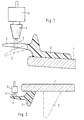
- the edge of a motor vehicle glass pane is shown on the in known a strand-shaped plastic profile 2 by extrusion from an extrusion nozzle, not shown, which is moved along the edge is applied.
- the plastic profile 2 can be extruded Reaction system, for example based on polyurethane, exist. It can but also from a thermoplastic material, especially one thermoplastic elastomer.
- One between the Plastic profile 2 and the surface of the automotive glass 1 applied Adhesion promoter layer is just like one possibly on the Disc edge of existing enamel decorative strips not shown.
- the not yet fully hardened plastic profile 2 has one cantilever lip 3, which in the illustrated embodiment in essentially parallel to the plane of the pane and over the edge of the automotive glass pane 1 extends.
- a compressed air jet 4 which consists of a Compressed air nozzle 5, which is arranged on the same robot arm as one Extrusion nozzle, not shown, for the plastic strand 2 and the accordingly the extrusion nozzle is tracked.
- the compressed air nozzle 5 is connected to a compressed air supply, not shown, of which the Compressed air via a control or regulating device 6 with an associated valve Compressed air nozzle 5 arrives. It is not shown that the distance of the Compressed air nozzle 5 to lip 3 and also the angular position of compressed air nozzle 2 are changeable relative to lip 3.
- the compressed air nozzle 5 can be circular, for example Have outlet cross section or be designed as a slot nozzle, wherein the arrangement should preferably be chosen so that the diameter of the compressed air jet 4 is not larger than the span of the lip 3.
- the compressed air nozzle 5 is at such a distance behind the Extrusion nozzle attached to the robot arm that that from the compressed air nozzle 5th escaping compressed air jet 4 on the still plastically deformable Plastic material of the lip 3 hits. Under the action of this compressed air jet 4 changes the orientation of the lip 3, like that in Figure 1 with dashed lines is reproduced.
- the size of the change depends depending on various parameters that are easy through simple experiments can be determined, for example from the distance between the Compressed air nozzle 5 and the lip 3, from the angular position of the compressed air nozzle 5 and their shape as well as the beam parameters. Generally it has proved to be sufficient if the compressed air jet 4 with a Excess pressure of 1 to 2 bar emerges from the compressed air nozzle 5, which is a distance from a few millimeters to a few centimeters from the lip 3 should.
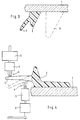
- a compressed air jet 4 is directed onto each side of the lip 3, the blowing directions of the compressed air nozzles 5 essentially one another are opposite and the compressed air nozzles 5 are arranged offset.
- Each according to the arrangement, direction and other parameters of the compressed air jets 4 can make 3 special with longer lips Cross-sectional shapes such as curvatures or waves are generated.
Landscapes
- Engineering & Computer Science (AREA)
- Mechanical Engineering (AREA)
- Chemical & Material Sciences (AREA)
- Composite Materials (AREA)
- Life Sciences & Earth Sciences (AREA)
- Chemical Kinetics & Catalysis (AREA)
- General Chemical & Material Sciences (AREA)
- Geochemistry & Mineralogy (AREA)
- Materials Engineering (AREA)
- Organic Chemistry (AREA)
- Extrusion Moulding Of Plastics Or The Like (AREA)
- Coating Apparatus (AREA)
Description
- Figur 1
- schematisch einen Schnitt durch ein auf eine Kfz-Glasscheibe extrudiertes strangförmiges Kunststoffprofil, das gemäß der Erfindung mittels eines Druckluftstrahls nachverformt wird,
- Figur 2
- eine andere Ausführung des Gegenstandes nach Figur 1,
- Figur 3
- die Kfz-Glasscheibe nach Figur 2 nach Verformung der Lippe,
- Figur 4
- eine andere Ausführung des Gegenstandes nach Figur 1.
Claims (15)
- Verfahren zum Aufbringen eines strangförmigen Kunststoffprofils längs des Randes einer (Kfz-) Glasscheibe, bei dem der Querschnitt des Kunststoffprofils nach dessen Aufbringen zumindest abschnittsweise bleibend verformt wird, dadurch gekennzeichnet , daß die Verformung mit Hilfe eines gasförmigen oder flüssigen Mediums erfolgt, bevor das Kunststoffmaterial vollständig ausgehärtet ist.
- Verfahren nach Anspruch 1, dadurch gekennzeichnet, daß ein erwärmtes oder gekühltes Medium verwendet wird.
- Verfahren nach einem der vorangehenden Ansprüche, dadurch gekennzeichnet, daß ein Medium mit einer die Aushärtung des Kunststoffmaterials beschleunigenden oder verlangsamenden Beimischung verwendet wird.
- Verfahren nach einem der vorangehenden Ansprüche , dadurch gekennzeichnet, daß die Verformung mit Hilfe eines strömenden Mediums erfolgt.
- Verfahren nach einem der vorangehenden Ansprüche, dadurch gekennzeichnet, daß das Medium als mindestens ein Strahl auf das Kunststoffprofil gerichtet wird.
- Verfahren nach Anspruch 5, dadurch gekennzeichnet, daß mit einem Druckgasstrahl gearbeitet wird.
- Verfahren nach Anspruch 6, dadurch gekennzeichnet, daß der Druckgasstrahl aus einem als Druckgasdüse gestalteten und mit mind. 1 bar Überdruck beaufschlagten Werkzeug austritt.
- Verfahren nach Anspruch 7, dadurch gekennzeichnet, daß die Druckgasdüse einen Düsenkopf mit mehreren Austrittsöffnungen aufweist.
- Verfahren nach Anspruch 7 oder 8, dadurch gekennzeichnet, daß die Druckgasdüse einen Düsenkopf mit einer der Endform des Kunststoffprofils angepaßten Form aufweist.
- Verfahren nach einem der vorangehenden Ansprüche, dadurch gekennzeichnet, daß der Querschnitt des Kunststoffprofils mittels eines parallel zur Längserstreckung des Kunststoffprofils bewegten Werkzeugs verformt wird.
- Verfahren nach Anspruch 10, wobei das Kunststoffprofil durch Extrusion aus einer längs des Randes bewegten Extrusionsdüse mit einer profilierten Düsenöffnung hergestellt wird, dadurch gekennzeichnet, daß das Werkzeug der Extrusionsdüse nachgeführt wird.
- Verfahren nach einem der Ansprüche 1 bis 9, dadurch gekennzeichnet, daß der Querschnitt des Kunststoffprofils abschnittsweise durch ein mit seiner Längserstreckung parallel zu dem zu verformenden Bereich angeordnetes langgestrecktes Werkzeug verformt wird.
- Anwendung des Verfahrens nach einem der vorangehenden Ansprüche bei Kunststoffprofilen, die mindestens eine freitragende Lippe aufweisen, wobei die nachträgliche Verformung eine Veränderung der Ausrichtung der Lippe umfaßt.
- Anwendung nach Anspruch 13, wobei zumindest ein Strahl des Mediums unter einem Winkel ungleich 90° auf die Lippe gerichtet wird.
- Anwendung nach einem der Ansprüche 13 oder 14, dadurch gekennzeichnet, daß auf jede Seite der Lippe zumindest ein Strahl des Mediums gerichtet wird, wobei die Strahlen mit im wesentlichen entgegengesetzter Richtung angeordnet sind.
Applications Claiming Priority (3)
| Application Number | Priority Date | Filing Date | Title |
|---|---|---|---|
| DE19627053 | 1996-07-05 | ||
| DE19627053A DE19627053C1 (de) | 1996-07-05 | 1996-07-05 | Verfahren zum Aufbringen eines profilierten Kunststoffstrangs längs des Randes einer Glasscheibe |
| PCT/EP1997/003426 WO1998001283A1 (de) | 1996-07-05 | 1997-07-01 | Verfahren zum aufbringen eines strangförmigen kunststoffprofils längs des randes einer glasscheibe |
Publications (2)
| Publication Number | Publication Date |
|---|---|
| EP0918613A1 EP0918613A1 (de) | 1999-06-02 |
| EP0918613B1 true EP0918613B1 (de) | 2001-09-12 |
Family
ID=7798984
Family Applications (1)
| Application Number | Title | Priority Date | Filing Date |
|---|---|---|---|
| EP97930464A Expired - Lifetime EP0918613B1 (de) | 1996-07-05 | 1997-07-01 | Verfahren zum aufbringen eines strangförmigen kunststoffprofils längs des randes einer glasscheibe |
Country Status (4)
| Country | Link |
|---|---|
| EP (1) | EP0918613B1 (de) |
| AU (1) | AU3440997A (de) |
| DE (2) | DE19627053C1 (de) |
| WO (1) | WO1998001283A1 (de) |
Cited By (1)
| Publication number | Priority date | Publication date | Assignee | Title |
|---|---|---|---|---|
| WO2024104606A1 (de) * | 2022-11-16 | 2024-05-23 | Cqlt Saargummi Technologies S.À.R.L. | Verfahren zur herstellung eines dichtungs- und kantenschutzprofils und extrusionswerkzeug zur bildung eines dichtungs- oder kantenschutzprofils |
Family Cites Families (10)
| Publication number | Priority date | Publication date | Assignee | Title |
|---|---|---|---|---|
| DE2447036C3 (de) * | 1974-10-02 | 1980-08-28 | Phoenix Ag, 2100 Hamburg | Verfahren zum Herstellen von gummielastischen Formteilen |
| DE4022484C1 (de) * | 1990-07-17 | 1991-07-11 | Gurit-Essex Ag, Freienbach, Ch | |
| DE4123588A1 (de) * | 1991-07-17 | 1993-01-21 | Ver Glaswerke Gmbh | Verfahren und vorrichtung zur herstellung eines fahrzeugfensters |
| JPH05213120A (ja) * | 1992-01-31 | 1993-08-24 | Tokai Kogyo Kk | ドアウェザ−ストリップ、及びその製造方法 |
| US5445780A (en) * | 1992-08-26 | 1995-08-29 | Tokai Kogyo Kabushiki Kaisha | Assembly of a windshield glass and a weather strip having a partly modified cross section and method of manufacturing same |
| EP0634263B1 (de) * | 1993-06-25 | 2000-03-01 | Asahi Glass Company Ltd. | Verfahren zur Herstellung von Fensterrahmen und Fensterpaneelen mit Fensterrahmen |
| DE4421299C2 (de) * | 1994-06-17 | 1996-04-11 | Sekurit Saint Gobain Deutsch | Verfahren und Vorrichtung zum Nachformen eines an einen Gegenstand anextrudierten Profilstrangs |
| GB2295349A (en) * | 1994-11-17 | 1996-05-29 | Draftex Ind Ltd | Extruding curved pipes |
| JP3856851B2 (ja) * | 1995-03-13 | 2006-12-13 | 旭硝子株式会社 | 合成樹脂枠体付き窓体の製造方法 |
| DE69611575T2 (de) * | 1995-06-13 | 2001-08-23 | Asahi Glass Co. Ltd., Tokio/Tokyo | Verfahren zum Herstellen einer Platte mit Kunststoffrahmen |
-
1996
- 1996-07-05 DE DE19627053A patent/DE19627053C1/de not_active Expired - Fee Related
-
1997
- 1997-07-01 WO PCT/EP1997/003426 patent/WO1998001283A1/de not_active Ceased
- 1997-07-01 AU AU34409/97A patent/AU3440997A/en not_active Abandoned
- 1997-07-01 DE DE59704608T patent/DE59704608D1/de not_active Expired - Fee Related
- 1997-07-01 EP EP97930464A patent/EP0918613B1/de not_active Expired - Lifetime
Cited By (1)
| Publication number | Priority date | Publication date | Assignee | Title |
|---|---|---|---|---|
| WO2024104606A1 (de) * | 2022-11-16 | 2024-05-23 | Cqlt Saargummi Technologies S.À.R.L. | Verfahren zur herstellung eines dichtungs- und kantenschutzprofils und extrusionswerkzeug zur bildung eines dichtungs- oder kantenschutzprofils |
Also Published As
| Publication number | Publication date |
|---|---|
| DE19627053C1 (de) | 1997-07-31 |
| EP0918613A1 (de) | 1999-06-02 |
| DE59704608D1 (de) | 2001-10-18 |
| AU3440997A (en) | 1998-02-02 |
| WO1998001283A1 (de) | 1998-01-15 |
Similar Documents
| Publication | Publication Date | Title |
|---|---|---|
| DE19961706B4 (de) | Verbindung einer Fahrzeugscheibe mit einem angrenzenden Bauteil | |
| WO1989004751A1 (fr) | Dispositif de fabrication de pieces moulees en plastique et utilisation du dispositif | |
| EP0995667A1 (de) | Verbundbauteil für Fahrzeugkarosserien | |
| DE2628549A1 (de) | Dichtungsstrang fuer fahrzeugtueren | |
| DE60211369T2 (de) | Verfahren und werkzeug zum umspritzen von glasscheiben mit einem kunststoffprofil. | |
| EP1176044B1 (de) | Verbundbauteil für Fahrzeugkarosserien sowie Verfahren und Vorrichtung für dessen Herstellung | |
| DE69611575T2 (de) | Verfahren zum Herstellen einer Platte mit Kunststoffrahmen | |
| DE69625156T2 (de) | Verfahren zur Herstellung einer Glasscheibe mit einem Profilrahmen aus Elastomer | |
| EP1209050A2 (de) | Wischeranordnung und Verfahren zum Herstellen einer Wischeranordnung | |
| DE9410787U1 (de) | Vorrichtung zum Auftragen von Abdichtungsmaterial auf Spundbohlenklauen und Spundbohlenklauen und Spundbohle mit Dichtung | |
| EP1817151A1 (de) | Kunststoffformteil und verfahren zur herstellung eines kunststoffformteils | |
| DE102007002946A1 (de) | Verfahren zur Herstellung einer Dichtung, insbesondere für ein Kraftfahrzeug, und eine solche Dichtung | |
| DE19627053C1 (de) | Verfahren zum Aufbringen eines profilierten Kunststoffstrangs längs des Randes einer Glasscheibe | |
| EP2922679B1 (de) | Verfahren zur herstellung eines flächigen kraftfahrzeugkarosserieelements | |
| DE4421299C2 (de) | Verfahren und Vorrichtung zum Nachformen eines an einen Gegenstand anextrudierten Profilstrangs | |
| EP0441287A1 (de) | Metallband als Einlage für Zier- und Dichtstreife | |
| EP3130440B1 (de) | Formteil und verfahren zur herstellung eines derartigen formteils | |
| EP0041154B1 (de) | Formschablone | |
| WO2004106044A2 (de) | Verbundbauteil und verfahren zu dessen herstellung | |
| EP0650768B1 (de) | Verfahren und Vorrichtung zum Formen und zum Auftragen eines Profilstrangs auf eine Unterlage | |
| DE102005001611C5 (de) | Mehrfarbige Gießhäute | |
| AT522081B1 (de) | Vorrichtung zum Aufbringen einer Deckschicht | |
| DE19714183C2 (de) | Verfahren zur Herstellung eines aus Fasermaterial oder Vlies bestehenden Hohlkörpers und Hohlkörper | |
| DE10058890C1 (de) | Verfahren zum fortlaufenden Herstellen von Haftverschlußteilen | |
| DE102007003366B4 (de) | Verfahren zur Herstellung von Formhäuten aus mehreren Kunststoffen |
Legal Events
| Date | Code | Title | Description |
|---|---|---|---|
| PUAI | Public reference made under article 153(3) epc to a published international application that has entered the european phase |
Free format text: ORIGINAL CODE: 0009012 |
|
| 17P | Request for examination filed |
Effective date: 19981216 |
|
| AK | Designated contracting states |
Kind code of ref document: A1 Designated state(s): BE DE FR IT |
|
| 17Q | First examination report despatched |
Effective date: 20000111 |
|
| GRAG | Despatch of communication of intention to grant |
Free format text: ORIGINAL CODE: EPIDOS AGRA |
|
| GRAG | Despatch of communication of intention to grant |
Free format text: ORIGINAL CODE: EPIDOS AGRA |
|
| GRAH | Despatch of communication of intention to grant a patent |
Free format text: ORIGINAL CODE: EPIDOS IGRA |
|
| GRAH | Despatch of communication of intention to grant a patent |
Free format text: ORIGINAL CODE: EPIDOS IGRA |
|
| RAP1 | Party data changed (applicant data changed or rights of an application transferred) |
Owner name: PILKINGTON AUTOMOTIVE DEUTSCHLAND GMBH |
|
| GRAA | (expected) grant |
Free format text: ORIGINAL CODE: 0009210 |
|
| AK | Designated contracting states |
Kind code of ref document: B1 Designated state(s): BE DE FR IT |
|
| REF | Corresponds to: |
Ref document number: 59704608 Country of ref document: DE Date of ref document: 20011018 |
|
| ET | Fr: translation filed | ||
| PLBE | No opposition filed within time limit |
Free format text: ORIGINAL CODE: 0009261 |
|
| STAA | Information on the status of an ep patent application or granted ep patent |
Free format text: STATUS: NO OPPOSITION FILED WITHIN TIME LIMIT |
|
| 26N | No opposition filed | ||
| PGFP | Annual fee paid to national office [announced via postgrant information from national office to epo] |
Ref country code: DE Payment date: 20040617 Year of fee payment: 8 |
|
| PGFP | Annual fee paid to national office [announced via postgrant information from national office to epo] |
Ref country code: FR Payment date: 20040720 Year of fee payment: 8 |
|
| PGFP | Annual fee paid to national office [announced via postgrant information from national office to epo] |
Ref country code: BE Payment date: 20040723 Year of fee payment: 8 |
|
| PG25 | Lapsed in a contracting state [announced via postgrant information from national office to epo] |
Ref country code: IT Free format text: LAPSE BECAUSE OF NON-PAYMENT OF DUE FEES;WARNING: LAPSES OF ITALIAN PATENTS WITH EFFECTIVE DATE BEFORE 2007 MAY HAVE OCCURRED AT ANY TIME BEFORE 2007. THE CORRECT EFFECTIVE DATE MAY BE DIFFERENT FROM THE ONE RECORDED. Effective date: 20050701 |
|
| PG25 | Lapsed in a contracting state [announced via postgrant information from national office to epo] |
Ref country code: BE Free format text: LAPSE BECAUSE OF NON-PAYMENT OF DUE FEES Effective date: 20050731 |
|
| PG25 | Lapsed in a contracting state [announced via postgrant information from national office to epo] |
Ref country code: DE Free format text: LAPSE BECAUSE OF NON-PAYMENT OF DUE FEES Effective date: 20060201 |
|
| PG25 | Lapsed in a contracting state [announced via postgrant information from national office to epo] |
Ref country code: FR Free format text: LAPSE BECAUSE OF NON-PAYMENT OF DUE FEES Effective date: 20060331 |
|
| REG | Reference to a national code |
Ref country code: FR Ref legal event code: ST Effective date: 20060331 |
|
| BERE | Be: lapsed |
Owner name: *PILKINGTON AUTOMOTIVE DEUTSCHLAND G.M.B.H. Effective date: 20050731 |