EP0918582B1 - Bördelvorrichtung - Google Patents
Bördelvorrichtung Download PDFInfo
- Publication number
- EP0918582B1 EP0918582B1 EP97932767A EP97932767A EP0918582B1 EP 0918582 B1 EP0918582 B1 EP 0918582B1 EP 97932767 A EP97932767 A EP 97932767A EP 97932767 A EP97932767 A EP 97932767A EP 0918582 B1 EP0918582 B1 EP 0918582B1
- Authority
- EP
- European Patent Office
- Prior art keywords
- flanging
- segments
- flanging device
- connecting rods
- different
- Prior art date
- Legal status (The legal status is an assumption and is not a legal conclusion. Google has not performed a legal analysis and makes no representation as to the accuracy of the status listed.)
- Expired - Lifetime
Links
- 238000009957 hemming Methods 0.000 title 1
- 229910000831 Steel Inorganic materials 0.000 claims description 11
- 239000010959 steel Substances 0.000 claims description 11
- 230000007246 mechanism Effects 0.000 claims description 6
- 230000002093 peripheral effect Effects 0.000 claims 1
- 238000002788 crimping Methods 0.000 description 16
- 238000010276 construction Methods 0.000 description 6
- 239000002184 metal Substances 0.000 description 4
- 239000000969 carrier Substances 0.000 description 3
- 230000008859 change Effects 0.000 description 2
- 230000008878 coupling Effects 0.000 description 2
- 238000010168 coupling process Methods 0.000 description 2
- 238000005859 coupling reaction Methods 0.000 description 2
- 238000000034 method Methods 0.000 description 2
- 230000004048 modification Effects 0.000 description 2
- 238000012986 modification Methods 0.000 description 2
- 230000000712 assembly Effects 0.000 description 1
- 238000000429 assembly Methods 0.000 description 1
- 230000008901 benefit Effects 0.000 description 1
- 230000000295 complement effect Effects 0.000 description 1
- 230000003292 diminished effect Effects 0.000 description 1
- 230000002452 interceptive effect Effects 0.000 description 1
- 238000003754 machining Methods 0.000 description 1
- 230000007704 transition Effects 0.000 description 1
Images




Classifications
-
- B—PERFORMING OPERATIONS; TRANSPORTING
- B21—MECHANICAL METAL-WORKING WITHOUT ESSENTIALLY REMOVING MATERIAL; PUNCHING METAL
- B21D—WORKING OR PROCESSING OF SHEET METAL OR METAL TUBES, RODS OR PROFILES WITHOUT ESSENTIALLY REMOVING MATERIAL; PUNCHING METAL
- B21D39/00—Application of procedures in order to connect objects or parts, e.g. coating with sheet metal otherwise than by plating; Tube expanders
- B21D39/02—Application of procedures in order to connect objects or parts, e.g. coating with sheet metal otherwise than by plating; Tube expanders of sheet metal by folding, e.g. connecting edges of a sheet to form a cylinder
- B21D39/021—Application of procedures in order to connect objects or parts, e.g. coating with sheet metal otherwise than by plating; Tube expanders of sheet metal by folding, e.g. connecting edges of a sheet to form a cylinder for panels, e.g. vehicle doors
-
- Y—GENERAL TAGGING OF NEW TECHNOLOGICAL DEVELOPMENTS; GENERAL TAGGING OF CROSS-SECTIONAL TECHNOLOGIES SPANNING OVER SEVERAL SECTIONS OF THE IPC; TECHNICAL SUBJECTS COVERED BY FORMER USPC CROSS-REFERENCE ART COLLECTIONS [XRACs] AND DIGESTS
- Y10—TECHNICAL SUBJECTS COVERED BY FORMER USPC
- Y10T—TECHNICAL SUBJECTS COVERED BY FORMER US CLASSIFICATION
- Y10T29/00—Metal working
- Y10T29/53—Means to assemble or disassemble
- Y10T29/53709—Overedge assembling means
- Y10T29/53717—Annular work
- Y10T29/53722—Annular work with radially acting tool inside annular work
Definitions
- the invention relates to a flanging device with the Features in the preamble of the main claim.
- Such a flanging device is from WO-A-95/21711 known. It has a crimping head, which several in Has segmented flared steels.
- the Flanging device also has a stroke drive for Generation of the flaring stroke and an adjusting device with a wedge drive for simultaneous retraction and extension of the segments.
- the segments form in the extended Operating position a flanged edge interrupted at the corner. They are the same size when entering and exiting Delivery routes and delivery speeds are moving.
- Such flanging devices are mainly for Workpieces with an internal opening, e.g. Vehicle doors with a window cutout, thought. In withdrawn rest position of the segments can Open and lower the flanging head in the workpiece opening. In the extended operating position, the segments flare the Sheet edges around.
- flanging devices are in practice in known various embodiments. You own a crimping head that divides one or more into segments divided and with a rotating in the operating position Has flanged steels provided. This previously known flanging devices have a two or multi-stage actuator that adjusts the segments moved in two or more groups one after the other. This requires multiple drives and means an increased one Tax and construction costs. This technique also costs Cycle time.
- the invention solves this problem with the features in the main claim.
- all segments can be moved simultaneously, with their oblique contact surfaces abutting one another flush in the extended operating position and forming a continuous, uninterrupted flanged edge at at least one corner region.
- the segments only need one drive.
- the flanging device according to the invention is therefore less expensive, more economical and faster.
- the contact surfaces of the segments are on the kinematics customized. We recommend that you avoid accidents Wedge angle between 20 ° to 50 °, preferably 35 ° to 40 °.
- the preferred embodiment of the actuator as Crank drive offers a stable and highly precise Construction.
- the cranks take one Stretch position and support the segments against the Flaring forces safely.
- the cranks By arranging the cranks in different heights on the crankshaft Cranks independently and without mutual Disorder turn, being of different lengths Can perform delivery strokes.
- the segments With this crank kinematics the segments can be moved at different speeds and avoid each other. Most of all, this is then an advantage if the flanged edge goes around the corner and the feed axes of the segments at an angle to one another are aligned.
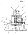
- the flanging device (1) in one uncut side view and in a longitudinal section from the same direction.
- the flanging device (1) is used for Machining a workpiece (2) in which it is for example a vehicle door with a Window cutout (3) is.
- the crimping device (1) is in the workpiece opening (3) or in Window cutout and is used for flanging the corner circumferential sheet metal inner edges (34).
- the workpiece (2) rests on a suitable one Workpiece holder (4) and is fixed on it.
- the Workpiece holder (4) surrounds the flanging device (1).
- the flanging device (1) has a lifting drive and Guide unit (7) with a crimping head that can be moved with it (6) and a frame (5).
- the crimping head (6) leads by means of the lifting drive (7) in the shown Embodiment vertical lifting or flanging movements out.
- the flaring stroke also runs horizontally or at an angle.
- the crimping head (6) has one or more crimping steels (8,9), which in the operating position (see FIG. 3) has a Form a flanged edge (11) all around the corner.
- the flared steels (8.9) are an exemplary embodiment. arranged one above the other, the upper flare steel (8) the pre-flaring and the lower flaring steel (9) the Finishing is used.
- the flare steels (8,9) each consist of several Segments (12,13,14,15,16) that are transverse to the stroke direction are arranged movably and with an adjusting device (22) can be extended and retracted.
- the segments (12,13,14,15,16) are flush with each other and form with the outer, the continuous, uninterrupted Flanged edge (11).
- the segments (12, 13, 14, 15, 16) are different withdrawn far and have a diminished Outer circumference.
- the crimping head (6) move up and down through the workpiece opening (3) and also allows a workpiece change.
- Fig. 1 illustrates the retreat position
- Fig. 2 the operating position in Side view.
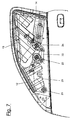
- Fig. 3 to 6 is the circumferential Flanged edge (11) angled according to the shape of the window or turned. This results in at least one preferably several corners or bends. Accordingly the segments (12, 13, 14, 15, 16) are distributed all around and in corresponding number available. 3 and 4 are five segments (12,13,14,15,16). 6 and 7 are There are three segments each (12, 13, 14). The segments can in turn be at least partially angled and go over corners with their flanged edge sections.
- the flanged edges (11) consist essentially of a vertical or inclined guide surface for angling the upstanding sheet metal edges or sheet metal inner edges (34).
- the Guide surfaces run in with both flare steels (8.9) a projecting flare (10).
- the inclination of the Surfaces and the rounding of the transition into the flare nose (10) are different sizes around the sheet metal edges first incline at pre-flanging and then at Fold over the finished flange.
- the segments (12,13,14,15,16) are from the Actuator (22) jointly driven and moved at the same time. They run differently long delivery strokes at different speeds out. As can be seen from FIGS. 3 to 7, the segments have (12,13,14,15,16) heads of different widths.
- the segments with the wider heads preferably in the corner areas and those with the narrower heads in between. The segments with the narrower heads prefer to move faster and with longer strokes than the segments with the wider ones Minds.
- the segments (12, 13, 14, 15, 16) have sloping heads Contact surfaces (17) with which they extend Operating position touch each other. In retracted At rest there is a distance between the Contact surfaces (17).
- the contact surfaces (17) are connected to the simultaneous segment movement required kinematics adapted and allow a collision-free release of the Segments (12,13,14,15,16) from each other and their trouble-free retraction and feed movement.
- the Contact surfaces (17) each have a point Wedge angle ⁇ to the adjacent flanged edge (11), the is between 20 ° and 50 °, preferably 30 ° and 45 °.
- 3 and 5 illustrate the contact areas (17) alternately inclined to the right and left.
- the Have segments (12, 14, 16) with the narrower heads preferably one or two inclined to the outside Contact surfaces (17). This results in a Complementary angle ⁇ of 180 ° - ⁇ .
- the segments (13, 15) with the broad minds, on the other hand, have two setbacks Contact surfaces (17), which at the top directly Form wedge angle ⁇ .
- the adjusting device (22) can have different designs his. In the preferred embodiment, it is as Designed crank mechanism (23). In the embodiment of 3 to 6, the crank mechanism (23) each has one Crankshaft (24). In the embodiment of FIG. 7 a second parallel crankshaft (25) as an auxiliary shaft available with the main shaft (24) directly over a Coupling rod (35) or indirectly via the drive is connected and rotates with it.
- the crankshafts (24,25) extend along the stroke direction of the Crimping head (6).
- the crankshaft (24) has one Rotary drive (26) which e.g. as hydraulic drive can be trained. In a modified one Embodiment can double Crankshaft arrangement two coupled drives available his.
- crank assemblies are from booms (32) to the Crankshafts (24.25) and crank rods (27,28,29,30,31) formed on the segments (12,13,14,15,16) are articulated.
- Fig. 4 shows the Crank arrangement schematic. 5 is a single one Crank for the segment (14) shown. The others are omitted for clarity. As in Fig. 4 made clear, the cranks are of different lengths.
- the Articulation points on the arms (32) have different ones Distances to the crankshaft (24.25) and also the Crank rods (27,28,29,30,31) have different ones Lengths.
- This crank geometry is used for generation delivery strokes of different lengths and speeds Segments (12,13,14,15,16).
- the crank rods (27,28,29,30,31) and boom (32) are correspondingly flat.
- the segments (12, 13, 14, 15, 16) have supports (18, 20) with which they are guided exactly.
- the carriers (18) are as Slide formed, which along a straight guide (19) be moved.
- the carriers (20) in Fig. 6 and 7 are as Swivel plates formed, which are along the Crankshaft (24, 25) aligned pivot bearing (21) rotate. 6 and 7 are the operating positions of the Segments (12,13,14) with solid lines and the Treatment positions shown with dashed lines.
- the carriers (18, 20) are shaped so that they are in Retracted position are fitted almost exactly into each other and on the other hand with obstacles inside the Crimping head (6) e.g. continuous tie rods or the like, do not collide.
- crank mechanism (23) is in the different Embodiments designed so that the cranks, i.e. the crank rods (27,28,29,30,31) and boom (32) a stretched position in the extended operating position take in. In this position they support the along the Flanging forces acting on the feed axes (33) optimally.
- the transverse or oblique forces are over the Guides (19) or pivot bearing (21) supported.
- the crimping head (6) and its Segments (12,13,14,15,16) it is advantageous initially one segment according to the direction and size of the delivery stroke to be determined. This is preferably the most bulky segment and a corner piece. It is best to give this a short one Give hub and thus the interfering edge for the collision-free passage in the workpiece opening (3) to be determined. Then the other segments (12,13,14,15,16) divided among themselves, their Infeed axes (33) are preferably essentially the same Have angles to each other.
- the Interfaces i.e. the position of the contact surfaces (17), fixed. As the top views illustrate, change thereby segments with narrow and segments with each other broad heads. The strokes are accordingly alternately long and short.
- the first segment will be the delivery stroke and the Infeed direction along the infeed axis (33) on the Interface, i.e. at the intersection of the flanged edge (11) and contact surface (17). Then for that Neighboring segment whose stroke and direction also on this Interface entered. The two endpoints of this Routes are interconnected. This The connecting line is then turned back approx. 2 ° to 15 °, to the game required in the retracted position guarantee. In its end position, this forms Connection line then the contact surface (17). With this Method, the wedge angles ⁇ result automatically Construction is carried out one after the other in the other segments applied. Then the construction can still be optimized.
- a crimp on the three overhead Detail pages In the exemplary embodiments shown the segment heads or the flanged edge (11) are convex bent. Alternatively, you can also at least in places be concave or straight. With a modified one Construction of a crimping head (6) can also Outside of a workpiece (3) are processed.
- the Flanging device (1) does not have to go through a Workpiece opening (3) extend, but can also on Stand outside edge of a workpiece (3).
- the adjusting device (22) be trained differently.
- a crank mechanism (23) can e.g. also a drive with several at the same time actuated actuating cylinders or the like suitable drive elements.
- the leadership the segments can also be designed differently.
Landscapes
- Engineering & Computer Science (AREA)
- Mechanical Engineering (AREA)
- Press Drives And Press Lines (AREA)
- Seal Device For Vehicle (AREA)
- Bending Of Plates, Rods, And Pipes (AREA)
- Bridges Or Land Bridges (AREA)
- Transmission Devices (AREA)
- Preliminary Treatment Of Fibers (AREA)
Description
Bei der erfindungsgemäßen Bördelvorrichtung können alle Segmente gleichzeitig bewegt werden, wobei sie in der ausgefahrenen Betriebsstellung mit ihren schrägen Kontaktflächen bündig aneinander stoßen und an zumindest einem Eckbereich eine umlaufende, ununterbrochene Bördelkante bilden. Die Segmente brauchen nur noch einen Antrieb. Die erfindungsgemäße Bördelvorrichtung ist dadurch kostengünstiger, wirtschaftlicher und schneller.
- Fig. 1 und 2
- die Bördelvorrichtung in einer Seitenansicht und in einem Längsschnitt,
- Fig. 3 und 4
- einen Bördelkopf mit fünf Segmenten in Draufsicht und in ausgefahrener Betriebsstellung sowie eingefahrener Ruhestellung,
- Fig. 5
- eine vergrößerte Detailansicht von einzelnen Segmenten und
- Fig. 6 und 7
- Varianten des Bördelkopfs mit verschiedenen Segmentausbildungen.
- 1
- Bördelvorrichtung
- 2
- Werkstück, Türe
- 3
- Öffnung, Fensterausschnitt
- 4
- Werkstückaufnahme
- 5
- Gestell
- 6
- Bördelkopf
- 7
- Hubantrieb
- 8
- Bördelstahl, Vorbördeln
- 9
- Bördelstahl, Fertigbördeln
- 10
- Bördelnase
- 11
- Bördelkante
- 12
- Segment
- 13
- Segment
- 14
- Segment
- 15
- Segment
- 16
- Segment
- 17
- Kontaktfläche
- 18
- Träger, Schieber
- 19
- Führung
- 20
- Träger, Schwenkplatte
- 21
- Schwenklager
- 22
- Stellvorrichtung
- 23
- Stellantrieb, Kurbeltrieb
- 24
- Kurbelwelle
- 25
- Kurbelwelle, Hilfswelle
- 26
- Drehantrieb
- 27
- Kurbelstange
- 28
- Kurbelstange
- 29
- Kurbelstange
- 30
- Kurbelstange
- 31
- Kurbelstange
- 32
- Ausleger
- 33
- Zustellachsen
- 34
- Blechrand, Blechinnenkante
- 35
- Koppelstange
Claims (10)
- Bördelvorrichtung zum Innenbördeln mit einem Bördelkopf (6), der ein oder mehrere in Segmente (12,13,14,15,16) unterteilte und mit einer Bördelkante (11) versehene Bördelstähle (8,9) aufweist, mit einem Hubantrieb (7) zur Erzeugung des Bördelhubs und mit einer Stellvorrichtung (22) zum Ein- und Ausfahren der Segmente (12,13,14,15,16), wobei die Stellvorrichtung (22) einen Stellantrieb (23) aufweist, der alle Segmente (12,13,14,15,16) gleichzeitig bewegt, dadurch gekennzeichnet, daß die Segmente (12,13,14,15,16) angepaßte schräge Kontaktflächen (17) aufweisen, mit denen sie in der ausgefahrenen Betriebsstellung bündig aneinander stoßen und an zumindest einem Eckbereich eine umlaufende ununterbrochene Bördelkante (11) bilden.
- Bördelvorrichtung nach Anspruch 1, dadurch gekennzeichnet, daß der Stellantrieb (22) die Segmente (12,13,14,15,16) mit unterschiedlich langen Zustellwegen und unterschiedlichen Zustellgeschwindigkeiten bewegt.
- Bördelvorrichtung nach Anspruch 1 oder 2, dadurch gekennzeichnet, daß die Kontaktflächen (17) einen Keilwinkel α von 20°-50°, vorzugsweise 30°-45°, zur Bördelkante (11) aufweisen.
- Bördelvorrichtung nach Anspruch 1, 2 oder 3, dadurch gekennzeichnet, daß der Stellantrieb (23) als Kurbeltrieb ausgebildet ist.
- Bördelvorrichtung nach Anspruch 4, dadurch gekennzeichnet, daß der Kurbeltrieb (23) ein oder mehrere gemeinsam angetriebene Kurbelwellen (24,25) aufweist, mit denen die Segmente (12,13,14,15,16) über Kurbelstangen (27,28,29,30,31) und Ausleger (32) verbunden sind.
- Bördelvorrichtung nach Anspruch 5, dadurch gekennzeichnet, daß die Kurbelstangen (27,28,29,30,31) in unterschiedlichen Höhen angeordnet sind.
- Bördelvorrichtung nach einem der Ansprüche 4 bis 6, dadurch gekennzeichnet, daß die Kurbelstangen (27,28,29,30,31) und Ausleger (32) unterschiedliche Längen aufweisen.
- Bördelvorrichtung nach einem der Ansprüche 4 bis 7, dadurch gekennzeichnet, daß die Kurbelstangen (27,28,29,30,31) und Ausleger (32) in Betriebsstellung eine Strecklage einnehmen.
- Bördelvorrichtung nach einem der Ansprüche 1 bis 8, dadurch gekennzeichnet, daß die Segmente (12,13,14,15,16) gerade geführt oder schwenkbar gelagert sind.
- Bördelvorrichtung nach einem der Ansprüche 1 bis 9, dadurch gekennzeichnet, daß die Zustellachsen (33) der Segmente (12,13,14,15,16) im wesentlichen gleiche Winkel untereinander aufweisen.
Applications Claiming Priority (3)
| Application Number | Priority Date | Filing Date | Title |
|---|---|---|---|
| DE29612192U DE29612192U1 (de) | 1996-07-16 | 1996-07-16 | Bördelvorrichtung |
| DE29612192U | 1996-07-16 | ||
| PCT/EP1997/003428 WO1998002260A1 (de) | 1996-07-16 | 1997-07-01 | Bördelvorrichtung |
Publications (2)
| Publication Number | Publication Date |
|---|---|
| EP0918582A1 EP0918582A1 (de) | 1999-06-02 |
| EP0918582B1 true EP0918582B1 (de) | 2000-05-03 |
Family
ID=8026444
Family Applications (1)
| Application Number | Title | Priority Date | Filing Date |
|---|---|---|---|
| EP97932767A Expired - Lifetime EP0918582B1 (de) | 1996-07-16 | 1997-07-01 | Bördelvorrichtung |
Country Status (6)
| Country | Link |
|---|---|
| US (1) | US6223581B1 (de) |
| EP (1) | EP0918582B1 (de) |
| JP (1) | JP2000514359A (de) |
| DE (2) | DE29612192U1 (de) |
| ES (1) | ES2145620T3 (de) |
| WO (1) | WO1998002260A1 (de) |
Families Citing this family (4)
| Publication number | Priority date | Publication date | Assignee | Title |
|---|---|---|---|---|
| US6418771B1 (en) * | 2000-10-23 | 2002-07-16 | Valiant Corporation | Interior hemming machine |
| US6460392B2 (en) * | 2001-02-28 | 2002-10-08 | Unova Ip Corp. | Flange bending apparatus |
| DE202014105862U1 (de) | 2014-12-04 | 2016-03-03 | Kuka Systems Gmbh | Falzwerkzeug und Falzeinrichtung |
| CN104772396A (zh) * | 2015-04-21 | 2015-07-15 | 重庆长安汽车股份有限公司 | 汽车顶盖天窗双开花驱动斜楔机构 |
Family Cites Families (12)
| Publication number | Priority date | Publication date | Assignee | Title |
|---|---|---|---|---|
| US1242627A (en) * | 1916-01-25 | 1917-10-09 | James M Winningham | Pipe-coupling machine. |
| US1722556A (en) * | 1925-10-14 | 1929-07-30 | Cameron Can Machinery Company | Can-body-forming machine |
| US1823047A (en) * | 1926-12-08 | 1931-09-15 | American Can Co | Method of and apparatus for beading of formed sheet metal articles |
| US2720241A (en) * | 1952-10-10 | 1955-10-11 | Carando Machine Works | Bead forming machine for barrel drums |
| FR1524200A (fr) | 1967-03-08 | 1968-05-10 | Renault | Procédé de fabrication de portes de véhicules |
| US3621699A (en) * | 1969-07-15 | 1971-11-23 | Tubal Ind Inc | Methods and apparatus for manufacturing shadow masks for colored television tubes |
| US4835825A (en) * | 1988-04-07 | 1989-06-06 | Warner Kenneth M | Machine for manufacturing a roof vent having a lead base |
| FR2645053B1 (fr) * | 1989-04-04 | 1994-11-25 | Renault | Montage de sertissage a table ouverte |
| FR2651699B1 (fr) | 1989-09-11 | 1992-02-07 | Steelweld France | Installation de pliage des rebords d'une portiere de vehicule automobile. |
| DE4330683C2 (de) * | 1993-09-10 | 1995-07-27 | Audi Ag | Falzvorrichtung |
| US5740691A (en) | 1994-02-14 | 1998-04-21 | Western Atlas U.K. Limited | Hemming machine |
| IT1278350B1 (it) * | 1995-02-02 | 1997-11-20 | Comau Spa | Dispositivo per la graffatura di elementi di lamiera metallica stampata. |
-
1996
- 1996-07-16 DE DE29612192U patent/DE29612192U1/de not_active Expired - Lifetime
-
1997
- 1997-07-01 US US09/214,673 patent/US6223581B1/en not_active Expired - Lifetime
- 1997-07-01 ES ES97932767T patent/ES2145620T3/es not_active Expired - Lifetime
- 1997-07-01 EP EP97932767A patent/EP0918582B1/de not_active Expired - Lifetime
- 1997-07-01 WO PCT/EP1997/003428 patent/WO1998002260A1/de not_active Ceased
- 1997-07-01 DE DE59701600T patent/DE59701600D1/de not_active Expired - Lifetime
- 1997-07-01 JP JP10505553A patent/JP2000514359A/ja active Pending
Also Published As
| Publication number | Publication date |
|---|---|
| JP2000514359A (ja) | 2000-10-31 |
| WO1998002260A1 (de) | 1998-01-22 |
| US6223581B1 (en) | 2001-05-01 |
| DE59701600D1 (de) | 2000-06-08 |
| DE29612192U1 (de) | 1997-10-09 |
| EP0918582A1 (de) | 1999-06-02 |
| ES2145620T3 (es) | 2000-07-01 |
Similar Documents
| Publication | Publication Date | Title |
|---|---|---|
| DE3601231C2 (de) | ||
| DE60103632T2 (de) | Stäbebiegevorrichtung mit auslöschbahrer biegenase | |
| EP0394531B1 (de) | Falzmaschine | |
| DE2840773C2 (de) | Halte- und Führungskorb für den Dorn eines Walzwerks | |
| DE3644251C2 (de) | ||
| DE19717232A1 (de) | Verfahren und Vorrichtung zum dreidimensionalen Biegen von Metall-Hohlprofilen | |
| DE1906741A1 (de) | Automatische Schweissvorrichtung zur Verbindung von Betonpfeilerabschnitten mit Stahlstirnplatten | |
| DE3627502C2 (de) | Rohrbiegemaschine | |
| DE2128717A1 (de) | Verfahren und Vorrichtung zur Herstellung einer Isolierverglasung | |
| DE1938225C3 (de) | Vorrichtung zum Fraesen von Woelbungen mit grossem Radius | |
| DE4019881A1 (de) | Schwenkbiegepresse zum abkanten und verformen von blechtafeln | |
| EP0200979B1 (de) | Rohrbiegemaschine | |
| DE3134652A1 (de) | Biegevorrichtung fuer glasscheiben | |
| EP0918582A1 (de) | Bördelvorrichtung | |
| DE69301476T2 (de) | Vorrichtung zum Unterstützen von Platten beim Stanzen und bei allgemeinen plastischen Verformungsvorgängen | |
| DE29914967U1 (de) | Bördeleinrichtung mit einem mehrachsigen Manipulator | |
| DE60217025T2 (de) | Biegevorrichtung und ihr Kontrollverfahren | |
| DE3619677C1 (de) | Vorrichtung zum Heben und Senken des Kopf- und des Fussteiles eines Bettrahmens | |
| DE10214275A1 (de) | Biegemaschine für Profile und Rundrohre | |
| DE2147079A1 (de) | Verfahren und Vorrichtung zum Anbringen von wendelförmig verlaufenden Rippen od. dgl. auf langgestreckten Gegenständen | |
| DE2405954C3 (de) | Vorrichtung zum Wenden unter gleichzeitigem Querfördern von prismatischem oder annähernd prismatischem Walzgut | |
| DE69718595T2 (de) | Schutzabdeckung für Werkzeugmaschinen | |
| DE4323728A1 (de) | Schweißvorrichtung für rechteckige Rahmen, insbesondere Fensterrahmen | |
| EP0857524A2 (de) | Drahtbund-Bildestation | |
| DE1226977B (de) | Schraubennaht-Rohrwerk |
Legal Events
| Date | Code | Title | Description |
|---|---|---|---|
| PUAI | Public reference made under article 153(3) epc to a published international application that has entered the european phase |
Free format text: ORIGINAL CODE: 0009012 |
|
| 17P | Request for examination filed |
Effective date: 19981209 |
|
| AK | Designated contracting states |
Kind code of ref document: A1 Designated state(s): DE ES FR GB IT SE |
|
| GRAG | Despatch of communication of intention to grant |
Free format text: ORIGINAL CODE: EPIDOS AGRA |
|
| RTI1 | Title (correction) |
Free format text: HEMMING DEVICE |
|
| 17Q | First examination report despatched |
Effective date: 19990719 |
|
| GRAG | Despatch of communication of intention to grant |
Free format text: ORIGINAL CODE: EPIDOS AGRA |
|
| GRAH | Despatch of communication of intention to grant a patent |
Free format text: ORIGINAL CODE: EPIDOS IGRA |
|
| GRAH | Despatch of communication of intention to grant a patent |
Free format text: ORIGINAL CODE: EPIDOS IGRA |
|
| GRAA | (expected) grant |
Free format text: ORIGINAL CODE: 0009210 |
|
| AK | Designated contracting states |
Kind code of ref document: B1 Designated state(s): DE ES FR GB IT SE |
|
| GBT | Gb: translation of ep patent filed (gb section 77(6)(a)/1977) |
Effective date: 20000504 |
|
| REF | Corresponds to: |
Ref document number: 59701600 Country of ref document: DE Date of ref document: 20000608 |
|
| REG | Reference to a national code |
Ref country code: ES Ref legal event code: FG2A Ref document number: 2145620 Country of ref document: ES Kind code of ref document: T3 |
|
| ITF | It: translation for a ep patent filed | ||
| ET | Fr: translation filed | ||
| PLBE | No opposition filed within time limit |
Free format text: ORIGINAL CODE: 0009261 |
|
| STAA | Information on the status of an ep patent application or granted ep patent |
Free format text: STATUS: NO OPPOSITION FILED WITHIN TIME LIMIT |
|
| 26N | No opposition filed | ||
| REG | Reference to a national code |
Ref country code: GB Ref legal event code: IF02 |
|
| REG | Reference to a national code |
Ref country code: GB Ref legal event code: 732E |
|
| REG | Reference to a national code |
Ref country code: ES Ref legal event code: PC2A |
|
| REG | Reference to a national code |
Ref country code: FR Ref legal event code: TP |
|
| REG | Reference to a national code |
Ref country code: DE Ref legal event code: R082 Ref document number: 59701600 Country of ref document: DE Representative=s name: ERNICKE UND KOLLEGEN, DE |
|
| REG | Reference to a national code |
Ref country code: DE Ref legal event code: R082 Ref document number: 59701600 Country of ref document: DE Representative=s name: PATENTANWAELTE ERNICKE UND KOLLEGEN, DE Effective date: 20140221 Ref country code: DE Ref legal event code: R082 Ref document number: 59701600 Country of ref document: DE Representative=s name: ERNICKE UND KOLLEGEN, DE Effective date: 20140221 Ref country code: DE Ref legal event code: R081 Ref document number: 59701600 Country of ref document: DE Owner name: KUKA SYSTEMS GMBH, DE Free format text: FORMER OWNER: D.V. AUTOMATION LTD., CHESSINGTON, SURREY, GB Effective date: 20140221 Ref country code: DE Ref legal event code: R081 Ref document number: 59701600 Country of ref document: DE Owner name: KUKA SYSTEMS GMBH, DE Free format text: FORMER OWNER: D.V. AUTOMATION LTD., CHESSINGTON, GB Effective date: 20140221 |
|
| REG | Reference to a national code |
Ref country code: ES Ref legal event code: PC2A Owner name: KUKA SYSTEMS GMBH Effective date: 20140514 |
|
| REG | Reference to a national code |
Ref country code: GB Ref legal event code: 732E Free format text: REGISTERED BETWEEN 20140515 AND 20140521 |
|
| REG | Reference to a national code |
Ref country code: FR Ref legal event code: TP Owner name: KUKA SYSTEMS GMBH, DE Effective date: 20140521 Ref country code: FR Ref legal event code: CA Effective date: 20140521 |
|
| REG | Reference to a national code |
Ref country code: FR Ref legal event code: PLFP Year of fee payment: 20 |
|
| PGFP | Annual fee paid to national office [announced via postgrant information from national office to epo] |
Ref country code: GB Payment date: 20160629 Year of fee payment: 20 Ref country code: ES Payment date: 20160613 Year of fee payment: 20 |
|
| PGFP | Annual fee paid to national office [announced via postgrant information from national office to epo] |
Ref country code: FR Payment date: 20160613 Year of fee payment: 20 |
|
| PGFP | Annual fee paid to national office [announced via postgrant information from national office to epo] |
Ref country code: IT Payment date: 20160720 Year of fee payment: 20 Ref country code: DE Payment date: 20160628 Year of fee payment: 20 |
|
| PGFP | Annual fee paid to national office [announced via postgrant information from national office to epo] |
Ref country code: SE Payment date: 20160712 Year of fee payment: 20 |
|
| REG | Reference to a national code |
Ref country code: DE Ref legal event code: R071 Ref document number: 59701600 Country of ref document: DE |
|
| REG | Reference to a national code |
Ref country code: GB Ref legal event code: PE20 Expiry date: 20170630 |
|
| PG25 | Lapsed in a contracting state [announced via postgrant information from national office to epo] |
Ref country code: GB Free format text: LAPSE BECAUSE OF EXPIRATION OF PROTECTION Effective date: 20170630 |
|
| REG | Reference to a national code |
Ref country code: ES Ref legal event code: FD2A Effective date: 20180508 |
|
| PG25 | Lapsed in a contracting state [announced via postgrant information from national office to epo] |
Ref country code: ES Free format text: LAPSE BECAUSE OF EXPIRATION OF PROTECTION Effective date: 20170702 |