EP0917396B1 - Verfahren und Anordnung zur Dämpfung von mechanischer Resonanz in einem Lautsprecher - Google Patents
Verfahren und Anordnung zur Dämpfung von mechanischer Resonanz in einem Lautsprecher Download PDFInfo
- Publication number
- EP0917396B1 EP0917396B1 EP98660121A EP98660121A EP0917396B1 EP 0917396 B1 EP0917396 B1 EP 0917396B1 EP 98660121 A EP98660121 A EP 98660121A EP 98660121 A EP98660121 A EP 98660121A EP 0917396 B1 EP0917396 B1 EP 0917396B1
- Authority
- EP
- European Patent Office
- Prior art keywords
- mass
- loudspeaker
- additional
- enclosure
- frame
- Prior art date
- Legal status (The legal status is an assumption and is not a legal conclusion. Google has not performed a legal analysis and makes no representation as to the accuracy of the status listed.)
- Expired - Lifetime
Links
Images



Classifications
-
- H—ELECTRICITY
- H04—ELECTRIC COMMUNICATION TECHNIQUE
- H04R—LOUDSPEAKERS, MICROPHONES, GRAMOPHONE PICK-UPS OR LIKE ACOUSTIC ELECTROMECHANICAL TRANSDUCERS; ELECTRIC HEARING AIDS; PUBLIC ADDRESS SYSTEMS
- H04R3/00—Circuits for transducers
- H04R3/002—Damping circuit arrangements for transducers, e.g. motional feedback circuits
-
- H—ELECTRICITY
- H04—ELECTRIC COMMUNICATION TECHNIQUE
- H04R—LOUDSPEAKERS, MICROPHONES, GRAMOPHONE PICK-UPS OR LIKE ACOUSTIC ELECTROMECHANICAL TRANSDUCERS; ELECTRIC HEARING AIDS; PUBLIC ADDRESS SYSTEMS
- H04R2209/00—Details of transducers of the moving-coil, moving-strip, or moving-wire type covered by H04R9/00 but not provided for in any of its subgroups
- H04R2209/027—Electrical or mechanical reduction of yoke vibration
Definitions
- the invention relates to a method according to the preamble of claim 1 for attenuating mechanical resonance in a loudspeaker.
- the invention also concerns an arrangement for attenuating the mechanical resonances of a loudspeaker.
- Thomasen see US 5,583,324 and (see US 5,240,221 ) have patented a vibration damper suitable for attachment to the enclosure wall, with the aim of reducing vibrations in enclosure walls. Because this method does not attempt to reduce the exciting vibration at its source, but rather, the secondary effects of wall motion, it fails to provide an effective approach to control vibration. Furthermore, it is a general object in the art to control vibrations over a wide bandwidth, whereby it can be shown that the disclosed embodiment is incapable within the constraints of practicable designs and materials to combine wide-band operation with high efficiency.
- Akroyd presents a construction wherein a tube made of an elastic material couples mechanically the dynamic loudspeaker element to the enclosure wall. This arrangement aims to support the frame of the loudspeaker element to reduce vibrations. At the same time, the tube acts as an acoustical resonant structure. While providing mechanical support, the structure fails to act as an efficient attenuator of enclosure resonances. The invention claims that this mechanical coupling achieves cancellation of vibrations, and thereby a reduction thereof.
- Tanaka presents a construction where the driver unit of a dynamic loudspeaker element is fixed to some external part of the loudspeaker enclosure other than its front wall. Additionally, there is provided an elastic means of fixing the frame of the loudspeaker element to the loudspeaker enclosure.
- the comments expressed about reference [2] apply equally well to this invention, because again there is provided a construction wherein the loudspeaker driver unit is mechanically attached to the enclosure using means having low mechanical losses, although herein the fixing point is not on the front of the enclosure. Because vibrations that are coupled to the enclosure walls normally occur on all walls of the enclosure, this invention will not lead to a good end result.
- the invention disclosed by Favali presents a loudspeaker enclosure with a construction that aims to attenuate mechanical vibrations by using plates made of an elastomer that bond together the walls of the enclosure and attach the loudspeaker element to the enclosure.
- the goal herein is to create shear forces into the elastomer that serves to convert mechanical energy into heat by internal friction in the material.
- This invention does not attempt to reduce the tendency of the loudspeaker element to cause mechanical vibrations.
- the structure is not efficient at resonant frequencies whose maximum displacement does not occur at the elastomer joints because there is no acoustic energy loss at these frequencies in the elastomer material.
- the present invention differs from the prior art in that it is a particular object of the invention to attenuate the mechanical vibration of the loudspeaker element driver unit, thereby making it unnecessary to attenuate vibrations in the enclosure structures.
- the present invention is different from and already basically superior to conventional constructions.
- the goal of the invention is attained by elastically attaching at least one additional mass to the magnet circuit of the loudspeaker, with the masses chosen such that the eigenfrequencies of the system will typically coincide with the mechanical resonances of the loudspeaker.
- the mechanical vibration energy produced by the magnet circuit tends to become transferred to the additional masses as a vibration of the additional masses, thus allowing the elastic coupling elements to absorb this energy by the frictional losses of the material.
- the total additional mass is chosen to be of the same order of magnitude as the mass of the magnet circuit.
- the masses may also differ by their order of magnitude from the mass of the magnet circuit.
- the invention offers substantial benefits.
- Control of resonance attenuation by the virtue of the present method is cheaper to implement than by using the prior-art techniques, because it is not necessary to modify the good and well-proven principles of loudspeaker construction in order to remove undesirable resonances.
- This is not possible if the loudspeaker element is attached to the enclosure using elastic means, if the magnet circuit is elastically attached to the frame of the loudspeaker element, or when using elastic structures in the loudspeaker enclosure.
- the additional masses and the elasticity and losses in their attachment it is possible to adjust the Q-value of the resonance peaks, the frequency range of control and the amount of vibration reduction.
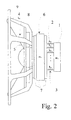
- a dynamic loudspeaker element shown therein includes a driver unit 6 that, under actuation by an electromagnetic force, displaces a radiating element 5, typically a cone.
- the driver unit is composed of a magnet circuit 7 and a voice coil (not shown) moving inside the air gap in the magnet circuit.
- the voice coil is glued to the air-displacing cone 5.
- the loudspeaker element comprises the mass of an air displacing mechanism 8 (i.e., the cone and voice coil) and the mass of the stationary part 7 (the magnet circuit) and the frame structure of the loudspeaker element 4.
- the cone-displacing driver unit comprising the magnet circuit and the voice coil moving in the air gap of the magnet circuit are attached to an external structure, typically the loudspeaker enclosure, by the perimeter 9 of the loudspeaker element frame 4.
- the frame 4 is typically made of a steel plate, plastic or die-cast metal, and it has a certain elasticity in the direction of the voice coil displacement axis. Also the front wall of the loudspeaker enclosure has some amount of elasticity that typically can be considered to add to the elasticity of the loudspeaker element frame 4.
- the electromagnetic force acts on the magnet circuit in the opposite direction to the force acting on the voice coil, thus causing the elasticity in the loudspeaker element frame and any elasticity in the mechanical attachment to the front wall of the enclosure to create one or more resonances with any mass mechanically coupled to either of these.
- the vibrational energy has favourable conditions to become transmitted from the magnet circuit into enclosure walls, causing them to vibrate. This is not favourable, and this transmission of mechanical vibration energy creates acoustical radiation from the enclosure walls that sum up with the acoustical radiation emitted by the loudspeaker element.
- the acoustical output is no longer determined by the loudspeaker element alone as originally intended, and the quality of the audio output will deteriorate.
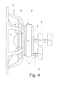
- the present invention discloses a method for attaching additional masses to the magnet circuit 7 such that the additional masses 1 will resonate with the magnet circuit 7 at frequencies that can be chosen so as to, e.g., coincide with the resonant frequency w 0 of the magnet circuit-frame system. Furthermore, these frequencies can be chosen to be any other frequencies at which the transmission of vibrational energy to the enclosure walls needs to be reduced.
- Figure 5(a) depicting one elastically attached additional mass (mass m 2 ) that forms a mass-spring system with the magnet circuit m 1 and the stiffness of the element frame k 1 and its losses c 1 .
- the displacement amplitude has a maximum at the resonant frequency of this system.
- Figure 5 depicts a system where a mass m 2 with an elasticity k 2 and loss factor c 2 has been attached elastically to this system.
- the resonant frequencies of this system of two coupled masses formed in this manner may be adjusted suitably by changing the elasticity k 2 and loss factor c 2 to minimize the displacement amplitude x 1 at the mechanical resonant frequency of the magnet circuit mass m 2-
- the ability of the additional mass to reduce the motional velocity depends on losses of the elastic attachment (component R 2 in the electro-mechanical analogy). By adjusting losses to a right level after setting the resonant frequency to be right by using suitable materials and correct mechanical dimensioning for the elastic attachment, it is possible to reduce mechanical vibrations down to any level and obtain any desired level of vibration attenuation.
- Equation 6 shows that at the resonant frequency w 0 , the Q-value of the resonance and therefore, the ability to attenuate mechanical vibrations, depends on the amount of additional mass and the elasticity of its attachment to the magnet system. If the loss factor of the elastic attachment remains constant, the desired Q-value can be obtained by selecting the right amount of additional mass and right elasticity of the attaching spring. If the additional mass remains constant, the amount of losses of the attachment must be reduced as the frequency decreases.
- an additional mass can be chosen, e.g., by measuring with the help of an acceleration transducer the resonant frequency of the mass-spring system formed by the magnet circuit and the loudspeaker element frame mounted in a loudspeaker enclosure. After the resonant frequency is known, to the magnet circuit 7 is attached an additional mass having a weight approximately equal to the mass of the magnet circuit, and the measurement is repeated.
- the correct value for the spring constant represented by a correct loss factor and elasticity
- An example of a system encountered in the practice of the art is represented by a loudspeaker element having a measured resonant angular frequency w 0 of 3300 rad/s and the magnet circuit 7 with a mass of 1.80 kg.
- the additional mass 1 is attached by using a spring made of nitrile rubber having a sheet thickness of 4 mm and an area of 4.5 cm 2 .
- the elasticity of the material is 4.3 MN/m.
- the amount of additional mass in this case is chosen to be 0.4 kg.
- This example shows how properties of the attachment spring affect the amount of the required additional mass, and that the optimum may not be exactly the same mass as that creates the mass-resonance system in the loudspeaker, but that the mass does have the same order of magnitude. Furthermore, in some cases it is advantageous to divide the additional mass and its attachment spring into subcomponents.
- the mass and the elasticity may be varied according to the principles described above to reduce the effect of the mechanical resonance w 0 down to a desired low level.
Landscapes
- Physics & Mathematics (AREA)
- Engineering & Computer Science (AREA)
- Acoustics & Sound (AREA)
- Signal Processing (AREA)
- Audible-Bandwidth Dynamoelectric Transducers Other Than Pickups (AREA)
- Diaphragms For Electromechanical Transducers (AREA)
- Obtaining Desirable Characteristics In Audible-Bandwidth Transducers (AREA)
Claims (10)
- Ein Verfahren zum Dämpfen mechanischer Resonanzen in einem Lautsprecher, der resonante Strukturen aufweist, die auf den Lautsprecher abgestimmt und an diesem angebracht sind,
wobei der Lautsprecher ein Lautsprecherelement und ein dem Lautsprecherelement zugeordnetes Lautsprechergehäuse aufweist,
wobei das Lautsprecherelement einen Rahmen (4) und eine Antriebseinheit (6) aufweist, wobei die Antriebseinheit (6) eine Magnetstruktur (7) aufweist,
und wobei ferner das Lautsprechergehäuse mechanisch mit der Antriebseinheit (6) oder mit dem Rahmen (4) gekuppelt ist,
dadurch gekennzeichnet, dass
mindestens eine zusätzliche Masse (1) elastisch (3) an der Magnetstruktur (7) oder an den Teilen des Rahmens (4) angebracht ist, die sich in der Nähe der Magnetstruktur befinden, wobei die elastisch (3) angebrachte zusätzliche Masse (1) eine Resonanzfrequenz aufweist, die in die Resonanz oder in einen Bereich der Resonanz der Antriebseinheit (6), des Rahmens (4) und/oder des Lautsprechergehäuses fällt. - Ein Verfahren gemäß Anspruch 1, dadurch gekennzeichnet, dass die Gesamtmasse der mindestens einen zusätzlichen Masse (1) so ausgewählt wird, dass die Gesamtmasse nahe bei der Masse des Magnetschaltkreises (7) liegt, wobei die gesamte zusätzliche Masse zwischen etwa dem 0,1-fachen bis 10-fachen der Masse des Magnetschaltkreises liegt.
- Ein Verfahren gemäß Anspruch 1, dadurch gekennzeichnet, dass mit der Magnetstruktur (7) die gesamte zusätzliche Masse elastisch gekuppelt ist, die mindestens eine zusätzliche Masse und Federstrukturen aufweist, die parallel oder in Reihe aneinander angeschlossen sind.
- Ein Verfahren gemäß Anspruch 1, dadurch gekennzeichnet, dass die zusätzlichen Massen (1) mittels eines elastischen Materials, wie beispielsweise mittels:- elastischen Gummis, Kunststoffes oder eines anderen Elastomers,- einer Metallfeder,- einer Luftfeder, oder- irgendeiner Kombination derselben angebracht sind.
- Ein Verfahren gemäß Anspruch 1, dadurch gekennzeichnet, dass die elastische Befestigung (3) der zusätzlichen Masse eine oder mehr getrennte, gleich elastische oder unterschiedlich elastische Teilfedern aufweist, die aus dem gleichen oder aus einem unterschiedlichen Material sein können, wobei die Teilfedern entweder in Reihe oder parallel aneinander angeschlossen sind.
- Eine Anordnung zum Dämpfen mechanischer Resonanzen in einem Lautsprecher,
wobei die Anordnung ein Lautsprecherelement und ein dem Lautsprecherelement zugeordnetes Lautsprechergehäuse aufweist,
wobei das Lautsprecherelement einen Rahmen (4) und eine Antriebseinheit (6) aufweist, wobei die Antriebseinheit (6) eine Magnetstruktur (7) aufweist,
und wobei ferner das Lautsprechergehäuse mechanisch mit der Antriebseinheit (6) oder mit dem Rahmen (4) gekuppelt ist,
dadurch gekennzeichnet, dass
die Anordnung mindestens eine zusätzliche Masse (1) aufweist, die elastisch (3) an der Magnetstruktur (7) oder an den Teilen des Rahmens (4) angebracht ist, die sich in der Nähe der Magnetstruktur befinden, wobei die elastisch (3) angebrachte zusätzliche Masse (1) eine Resonanzfrequenz aufweist, die in die Resonanz oder in einen Bereich der Resonanz der Antriebseinheit (6), des Rahmens (4) und/oder des Lautsprechergehäuses fällt. - Eine Anordnung gemäß Anspruch 6, dadurch gekennzeichnet, dass die zusätzlichen Massen (1) eine Masse aufweisen, die in derselben Größenordnung wie die Masse des Magnetschaltkreises (7) liegt, wobei die Gesamtmasse der zusätzlichen Massen das 0,1-fache bis 10-fache der Masse des Magnetschaltkreises (7) beträgt.
- Eine Anordnung gemäß Anspruch 6, dadurch gekennzeichnet, dass die zusätzlichen Massen (1) mittels eines elastischen Materials, wie beispielsweise mittels:- elastischen Gummis, Kunststoffes oder eines anderen Elastomers,- einer Metallfeder,- einer Luftfeder, oder- irgendeiner Kombination derselben angebracht sind.
- Eine Anordnung gemäß Anspruch 6, dadurch gekennzeichnet, dass die elastische Befestigung (3) der zusätzlichen Masse eine oder mehr getrennte, gleich elastische oder unterschiedlich elastische Teilfedern aufweist, die aus dem gleichen oder aus einem unterschiedlichen Material sein können, wobei die Teilfedern entweder in Reihe oder parallel aneinander angeschlossen sind.
- Eine Anordnung gemäß Anspruch 6, dadurch gekennzeichnet, dass die zusätzlichen Massen (6) aus einem festen Material hergestellt sind.
Applications Claiming Priority (2)
| Application Number | Priority Date | Filing Date | Title |
|---|---|---|---|
| FI974217 | 1997-11-12 | ||
| FI974217A FI104302B1 (fi) | 1997-11-12 | 1997-11-12 | Menetelmä ja laitteisto kaiuttimen mekaanisten resonanssien vaimentamiseksi |
Publications (3)
| Publication Number | Publication Date |
|---|---|
| EP0917396A2 EP0917396A2 (de) | 1999-05-19 |
| EP0917396A3 EP0917396A3 (de) | 2004-12-01 |
| EP0917396B1 true EP0917396B1 (de) | 2010-08-25 |
Family
ID=8549928
Family Applications (1)
| Application Number | Title | Priority Date | Filing Date |
|---|---|---|---|
| EP98660121A Expired - Lifetime EP0917396B1 (de) | 1997-11-12 | 1998-11-11 | Verfahren und Anordnung zur Dämpfung von mechanischer Resonanz in einem Lautsprecher |
Country Status (5)
| Country | Link |
|---|---|
| US (1) | US6373956B1 (de) |
| EP (1) | EP0917396B1 (de) |
| JP (1) | JP4615638B2 (de) |
| DE (1) | DE69841856D1 (de) |
| FI (1) | FI104302B1 (de) |
Families Citing this family (18)
| Publication number | Priority date | Publication date | Assignee | Title |
|---|---|---|---|---|
| GB2350965B (en) * | 1999-06-10 | 2001-08-22 | Stefan Gamble | Loudspeaker cabinet and microphone housing internal damping system |
| JP3484143B2 (ja) * | 1999-12-02 | 2004-01-06 | 株式会社タイムドメイン | スピーカ装置 |
| JP2001300422A (ja) * | 2000-04-21 | 2001-10-30 | Citizen Electronics Co Ltd | 多機能変換器とその駆動方法 |
| JP4153156B2 (ja) | 2000-11-10 | 2008-09-17 | 富士通テン株式会社 | スピーカ装置 |
| JP4144197B2 (ja) * | 2001-07-04 | 2008-09-03 | 新科實業有限公司 | 振動抑制機構及び振動抑制機構を備えたヘッドジンバルアセンブリ |
| US7551749B2 (en) | 2002-08-23 | 2009-06-23 | Bose Corporation | Baffle vibration reducing |
| US20070177746A1 (en) * | 2003-07-02 | 2007-08-02 | Kazuhiro Kobayashi | Panel type speaker |
| KR20050031778A (ko) * | 2003-09-30 | 2005-04-06 | 삼성광주전자 주식회사 | 진동감쇠장치 및 이를 갖춘 밀폐형 압축기 |
| EP1630788B1 (de) * | 2004-08-26 | 2012-04-18 | Airbus Operations GmbH | Vorrichtung und Verfahren zur Reduktion von Schall einer Rauschquelle in beschränkten Frequenzbereichen |
| US7844068B1 (en) * | 2005-01-05 | 2010-11-30 | Linear Corporation | Wall mounted speaker system, apparatus and method |
| US7828113B1 (en) | 2007-04-02 | 2010-11-09 | Kim Dao | Methods and apparatus for controlling vibration of enclosures, particularly loudspeaker enclosures |
| US8180076B2 (en) | 2008-07-31 | 2012-05-15 | Bose Corporation | System and method for reducing baffle vibration |
| CN102771139B (zh) | 2009-12-17 | 2015-08-19 | 珍尼雷克公司 | 驱动单元安装装置和扬声器 |
| GB2488758A (en) | 2011-03-02 | 2012-09-12 | Gp Acoustics Uk Ltd | Bass reflex loudspeaker has acoustic leakage in walls of port duct |
| GB2491108B (en) * | 2011-05-18 | 2014-06-04 | Gp Acoustics Uk Ltd | Loudspeaker |
| US12300207B2 (en) * | 2022-06-24 | 2025-05-13 | Toyota Motor Engineering & Manufacturing North America, Inc. | Flexural wave absorbers for wave and vibration isolation in thin walled structures |
| JP2025527302A (ja) * | 2022-08-04 | 2025-08-20 | ベアフット サウンド エルエルシー | ラウドスピーカにおける反力を低減する方法及び装置 |
| WO2025065587A1 (zh) * | 2023-09-28 | 2025-04-03 | 瑞声科技(南京)有限公司 | 一种扬声器 |
Family Cites Families (11)
| Publication number | Priority date | Publication date | Assignee | Title |
|---|---|---|---|---|
| JPS606157B2 (ja) * | 1977-07-25 | 1985-02-15 | ソニー株式会社 | スピ−カ |
| DE3037227A1 (de) | 1980-10-02 | 1982-04-29 | Alfred 2800 Bremen Rinkowski | Lautsprecher mit koerperschallresonator |
| US4598178A (en) | 1983-12-16 | 1986-07-01 | Rollins William L | Means for critically damping a dynamic loudspeaker |
| JPS6121699A (ja) * | 1984-07-10 | 1986-01-30 | Pioneer Electronic Corp | 体感音響振動装置 |
| DE3527501A1 (de) * | 1984-09-03 | 1986-03-13 | Sanden Corp., Isesaki, Gunma | Dynamische wandlereinrichtung |
| GB2192041B (en) * | 1986-06-24 | 1990-10-10 | Fokker Bv | Vibration absorber with controllable resonance frequency |
| US4710656A (en) * | 1986-12-03 | 1987-12-01 | Studer Philip A | Spring neutralized magnetic vibration isolator |
| FR2674092B3 (fr) * | 1991-03-15 | 1993-02-05 | Focal Sa | Haut-parleur perfectionne. |
| BE1004807A3 (nl) * | 1991-03-19 | 1993-02-02 | Schellekens Ivan | Het weergeven van geluid zonder mechanische intermodulatievervorming. |
| JP3144230B2 (ja) * | 1994-09-01 | 2001-03-12 | 松下電器産業株式会社 | 低音再生スピーカ |
| US6195442B1 (en) * | 1999-08-27 | 2001-02-27 | The United States Of America As Represented By The Secretary Of The Air Force | Passive vibroacoustic attenuator for structural acoustic control |
-
1997
- 1997-11-12 FI FI974217A patent/FI104302B1/fi not_active IP Right Cessation
-
1998
- 1998-11-11 DE DE69841856T patent/DE69841856D1/de not_active Expired - Lifetime
- 1998-11-11 EP EP98660121A patent/EP0917396B1/de not_active Expired - Lifetime
- 1998-11-12 US US09/190,175 patent/US6373956B1/en not_active Expired - Lifetime
- 1998-11-12 JP JP32243998A patent/JP4615638B2/ja not_active Expired - Lifetime
Also Published As
| Publication number | Publication date |
|---|---|
| JPH11234794A (ja) | 1999-08-27 |
| FI104302B (fi) | 1999-12-15 |
| JP4615638B2 (ja) | 2011-01-19 |
| US6373956B1 (en) | 2002-04-16 |
| EP0917396A3 (de) | 2004-12-01 |
| DE69841856D1 (de) | 2010-10-07 |
| FI974217A0 (fi) | 1997-11-12 |
| FI974217A7 (fi) | 1999-05-13 |
| FI104302B1 (fi) | 1999-12-15 |
| EP0917396A2 (de) | 1999-05-19 |
Similar Documents
| Publication | Publication Date | Title |
|---|---|---|
| EP0917396B1 (de) | Verfahren und Anordnung zur Dämpfung von mechanischer Resonanz in einem Lautsprecher | |
| AU725754B2 (en) | Loudspeakers | |
| KR100777888B1 (ko) | 트랜스듀서 | |
| US4951930A (en) | Insulator for use in automotive suspension or the like | |
| CN1653849B (zh) | 转换器 | |
| JP3192100B2 (ja) | マイクロホン | |
| KR20010043227A (ko) | 증가된 컴플라이언스를 가지며 나선형 댐퍼에 의해탄성적으로 지지되는 마그네틱 회로를 가지는 진동액추에이터 | |
| US20070263886A1 (en) | Transducer | |
| US7636447B2 (en) | Acoustic bracket system | |
| CN101611438A (zh) | 隔音板及具备其的隔音装置 | |
| US6279679B1 (en) | Selectively tuned vibration absorber | |
| EP1744302A2 (de) | Schwingungserregter Schalldämpfer mit dynamischer Abstimmung | |
| EP1940199A1 (de) | Lautsprecher, membran für einen lautsprecher und aufhängung | |
| EP1491405A1 (de) | Lautsprecher zur Montage in einem Fahrzeug | |
| US6286782B1 (en) | Apparatus and method for reducing vibrations of a structure particularly a helicopter | |
| EP1410680B1 (de) | Plattenlautsprecher | |
| US20010048751A1 (en) | Elongate panel loudspeaker | |
| US7062051B2 (en) | Acoustic device | |
| CN114339536B (zh) | 无源辐射器单元及包括该无源辐射器单元的扬声器系统 | |
| EP1425937B1 (de) | Verfahren zur Verbesserung des Modal Resonanzfrequenz Verteilung eines Panels | |
| JP2004028125A (ja) | ダイナミックダンパ | |
| JP3139125B2 (ja) | エンジンの制振構造 | |
| JPS643436B2 (de) | ||
| GB2373126A (en) | Loudspeaker driver with adapted natural resonance frequency | |
| JP2026052947A (ja) | 車体構造 |
Legal Events
| Date | Code | Title | Description |
|---|---|---|---|
| PUAI | Public reference made under article 153(3) epc to a published international application that has entered the european phase |
Free format text: ORIGINAL CODE: 0009012 |
|
| AK | Designated contracting states |
Kind code of ref document: A2 Designated state(s): AT BE CH CY DE DK ES FI FR GB GR IE IT LI LU MC NL PT SE |
|
| AX | Request for extension of the european patent |
Free format text: AL;LT;LV;MK;RO;SI |
|
| PUAL | Search report despatched |
Free format text: ORIGINAL CODE: 0009013 |
|
| AK | Designated contracting states |
Kind code of ref document: A3 Designated state(s): AT BE CH CY DE DK ES FI FR GB GR IE IT LI LU MC NL PT SE |
|
| AX | Request for extension of the european patent |
Extension state: AL LT LV MK RO SI |
|
| RIC1 | Information provided on ipc code assigned before grant |
Ipc: 7H 04R 1/28 B Ipc: 7H 04R 3/00 A |
|
| 17P | Request for examination filed |
Effective date: 20050120 |
|
| AKX | Designation fees paid |
Designated state(s): DE FR GB IT |
|
| 17Q | First examination report despatched |
Effective date: 20060803 |
|
| GRAP | Despatch of communication of intention to grant a patent |
Free format text: ORIGINAL CODE: EPIDOSNIGR1 |
|
| GRAS | Grant fee paid |
Free format text: ORIGINAL CODE: EPIDOSNIGR3 |
|
| GRAA | (expected) grant |
Free format text: ORIGINAL CODE: 0009210 |
|
| AK | Designated contracting states |
Kind code of ref document: B1 Designated state(s): DE FR GB IT |
|
| REG | Reference to a national code |
Ref country code: GB Ref legal event code: FG4D |
|
| REF | Corresponds to: |
Ref document number: 69841856 Country of ref document: DE Date of ref document: 20101007 Kind code of ref document: P |
|
| PLBE | No opposition filed within time limit |
Free format text: ORIGINAL CODE: 0009261 |
|
| STAA | Information on the status of an ep patent application or granted ep patent |
Free format text: STATUS: NO OPPOSITION FILED WITHIN TIME LIMIT |
|
| 26N | No opposition filed |
Effective date: 20110526 |
|
| REG | Reference to a national code |
Ref country code: DE Ref legal event code: R097 Ref document number: 69841856 Country of ref document: DE Effective date: 20110526 |
|
| REG | Reference to a national code |
Ref country code: FR Ref legal event code: PLFP Year of fee payment: 18 |
|
| REG | Reference to a national code |
Ref country code: FR Ref legal event code: PLFP Year of fee payment: 19 |
|
| REG | Reference to a national code |
Ref country code: FR Ref legal event code: PLFP Year of fee payment: 20 |
|
| PGFP | Annual fee paid to national office [announced via postgrant information from national office to epo] |
Ref country code: FR Payment date: 20171121 Year of fee payment: 20 Ref country code: DE Payment date: 20171121 Year of fee payment: 20 |
|
| PGFP | Annual fee paid to national office [announced via postgrant information from national office to epo] |
Ref country code: GB Payment date: 20171123 Year of fee payment: 20 Ref country code: IT Payment date: 20171124 Year of fee payment: 20 |
|
| REG | Reference to a national code |
Ref country code: DE Ref legal event code: R071 Ref document number: 69841856 Country of ref document: DE |
|
| REG | Reference to a national code |
Ref country code: GB Ref legal event code: PE20 Expiry date: 20181110 |
|
| PG25 | Lapsed in a contracting state [announced via postgrant information from national office to epo] |
Ref country code: GB Free format text: LAPSE BECAUSE OF EXPIRATION OF PROTECTION Effective date: 20181110 |