EP0916853B1 - Elektrohydraulisches Betätigungsglied - Google Patents
Elektrohydraulisches Betätigungsglied Download PDFInfo
- Publication number
- EP0916853B1 EP0916853B1 EP98309079A EP98309079A EP0916853B1 EP 0916853 B1 EP0916853 B1 EP 0916853B1 EP 98309079 A EP98309079 A EP 98309079A EP 98309079 A EP98309079 A EP 98309079A EP 0916853 B1 EP0916853 B1 EP 0916853B1
- Authority
- EP
- European Patent Office
- Prior art keywords
- piston
- electro
- solenoid valve
- flow path
- hydraulic actuator
- Prior art date
- Legal status (The legal status is an assumption and is not a legal conclusion. Google has not performed a legal analysis and makes no representation as to the accuracy of the status listed.)
- Expired - Lifetime
Links
- 239000012530 fluid Substances 0.000 claims description 29
- 230000033001 locomotion Effects 0.000 claims description 18
- 238000005086 pumping Methods 0.000 claims description 13
- 238000006073 displacement reaction Methods 0.000 claims description 3
- 230000000694 effects Effects 0.000 claims description 3
- 238000009428 plumbing Methods 0.000 claims description 3
- 238000012544 monitoring process Methods 0.000 claims description 2
- 230000007246 mechanism Effects 0.000 description 6
- 230000008014 freezing Effects 0.000 description 2
- 238000007710 freezing Methods 0.000 description 2
- 239000000126 substance Substances 0.000 description 2
- 239000012190 activator Substances 0.000 description 1
- 238000006243 chemical reaction Methods 0.000 description 1
- 230000006835 compression Effects 0.000 description 1
- 238000007906 compression Methods 0.000 description 1
- 239000000383 hazardous chemical Substances 0.000 description 1
- 230000007257 malfunction Effects 0.000 description 1
- 230000011664 signaling Effects 0.000 description 1
Images


Classifications
-
- F—MECHANICAL ENGINEERING; LIGHTING; HEATING; WEAPONS; BLASTING
- F15—FLUID-PRESSURE ACTUATORS; HYDRAULICS OR PNEUMATICS IN GENERAL
- F15B—SYSTEMS ACTING BY MEANS OF FLUIDS IN GENERAL; FLUID-PRESSURE ACTUATORS, e.g. SERVOMOTORS; DETAILS OF FLUID-PRESSURE SYSTEMS, NOT OTHERWISE PROVIDED FOR
- F15B15/00—Fluid-actuated devices for displacing a member from one position to another; Gearing associated therewith
- F15B15/02—Mechanical layout characterised by the means for converting the movement of the fluid-actuated element into movement of the finally-operated member
- F15B15/06—Mechanical layout characterised by the means for converting the movement of the fluid-actuated element into movement of the finally-operated member for mechanically converting rectilinear movement into non- rectilinear movement
- F15B15/065—Mechanical layout characterised by the means for converting the movement of the fluid-actuated element into movement of the finally-operated member for mechanically converting rectilinear movement into non- rectilinear movement the motor being of the rack-and-pinion type
-
- F—MECHANICAL ENGINEERING; LIGHTING; HEATING; WEAPONS; BLASTING
- F15—FLUID-PRESSURE ACTUATORS; HYDRAULICS OR PNEUMATICS IN GENERAL
- F15B—SYSTEMS ACTING BY MEANS OF FLUIDS IN GENERAL; FLUID-PRESSURE ACTUATORS, e.g. SERVOMOTORS; DETAILS OF FLUID-PRESSURE SYSTEMS, NOT OTHERWISE PROVIDED FOR
- F15B15/00—Fluid-actuated devices for displacing a member from one position to another; Gearing associated therewith
- F15B15/18—Combined units comprising both motor and pump
-
- F—MECHANICAL ENGINEERING; LIGHTING; HEATING; WEAPONS; BLASTING
- F15—FLUID-PRESSURE ACTUATORS; HYDRAULICS OR PNEUMATICS IN GENERAL
- F15B—SYSTEMS ACTING BY MEANS OF FLUIDS IN GENERAL; FLUID-PRESSURE ACTUATORS, e.g. SERVOMOTORS; DETAILS OF FLUID-PRESSURE SYSTEMS, NOT OTHERWISE PROVIDED FOR
- F15B20/00—Safety arrangements for fluid actuator systems; Applications of safety devices in fluid actuator systems; Emergency measures for fluid actuator systems
- F15B20/002—Electrical failure
Definitions
- This invention relates generally to an electro-hydraulic actuator, and particularly to a fail-safe electro-hydraulic valve actuator.
- One type of electro-mechanical system known in the art comprises an electric valve actuator and a spring return mechanism.
- This actuator uses a motor and gearbox to actuate a valve and to wind up a spring which reverses upon loss of electrical signal or power to the actuator.
- the actuator can operate to hold the spring in the open position continuously or to actuate the spring with every turn.
- Actuators which energize the spring during every actuation have a disadvantage of increasing the power requirements to run the actuator motor to twice that required to run a motor of an actuator not having a fail-safe mechanism. If the spring is instead continuously held in the energized position, it is not exercised until it is called upon to actuate the valve, thus increasing the likelihood of sticking components and actuator malfunction.
- electric valve actuators use a battery backup to reverse actuator direction when a loss of power is detected at the actuator.
- batteries will only actuate the valve a limited number of times depending on the storage potential of the battery and the power requirements of the actuator. Failure to maintain the battery charged and in good working order will negate the fail-safe feature of the actuator.
- a third way of providing fail-safe mechanisms for electrically actuated valves is to use a spring return arrangement whereby fluid is pumped into a chamber by a hydraulic pump driven by an electric motor. The fluid moves a piston(s) and rotates the output shaft, while compressing and energizing the retum spring(s).
- An electrically controlled solenoid valve maintains the pressure developed in the chamber. Upon loss of power or electrical signal, the solenoid valve is opened which allows the spring(s) to return the fluid from the pressurized chamber to the non-pressurized reservoir.
- Prior art electro-hydraulic actuators such as those mentioned above have several disadvantages, including: 1) using scotch yoke and spur gear systems with a piston rod for changing linear motion in the actuator to rotary output motion, thus limiting rotary motion to a maximum of 90 degrees; 2) using external conduits which are susceptible to freezing, breakage and leakage; 3) using external cylinders to house fail safe springs, thus requiring rod spring guide systems to ensure linear compression of the spring without distortion; and 4) using only one solenoid valve for both fail-safe operation and position controlling.
- An electro-hydraulic actuator comprises an actuator casing and a piston/rack means within the casing having walls reciprocating linearly to effect linear movements, the reciprocating walls defining a centre chamber therebetween and two outside chambers inside the casing.
- An output shaft is in communication with said piston/rack means for driving a valve, the output shaft effecting rotational movements in response to the linear movements of said piston/rack means.
- a resilient return means is provided which engages the reciprocating walls of the piston/rack means and inner end walls of the casing, and biases the reciprocating walls of the piston/rack means to a closed position.
- the actuator further includes a pumping means, A primary flow path is provided for transferring fluid from the pumping means to a first output port and into the centre chamber, wherein the fluid causes the piston/rack means to expand on the casing and transmit linear motion of the piston/rack means to the output shaft.
- a fail-safe solenoid valve system comprising a secondary flow path connecting to and extending from the primary flow path to a second outlet port opening into at least one of the outside chambers, and a normally open solenoid valve in the secondary flow path preventing flow through the secondary flow path wherein, upon loss of power to the actuator, the solenoid valve opens allowing the resilient return means to force fluid out of the centre chamber, through the primary and secondary flow paths, and into at least one of the outside chambers, and to return the piston/rack means to a closed position, thereby rotating the output shaft in communication with a device to be turned.
- the actuator is a self-contained unit having internal primary and secondary flow paths without external plumbing connection.
- the activator further includes a check valve located at the outlet of the pumping means.
- the piston/rack means is capable of transmitting enough linear movement so that the output shaft can rotate up to 360 degrees.
- the electro-hydraulic actuator may comprise at least one internal guide rod for guiding the linear motion of the piston-rack means in the casing, wherein, preferably, at least one of the internal guide rods contains the first output port from the primary flow path and fluid flowing to and from the primary flow path to the centre chamber flows through the internal guide rod and the first output port in said internal guide rod.
- a positioning solenoid valve system may be provided including a tertiary internal flow path connecting to and extending from said primary internal flow path to said second outlet port and a normally closed positioning solenoid valve in said tertiary flow path preventing flow through said tertiary flow path wherein, to partially close said actuator piston/rack means, said positioning solenoid valve is opened buy a positioning controller allowing said resilient return means to force fluid out of said centre chamber, through said primary and tertiary internal flow paths, and into at least one of said outside chambers and to move said piston/rack means to a partially closed position whereby said positioning controller closes said positioning solenoid valve.
- the positioning solenoid valve preferably has a smaller flow capacity than said fail-safe solenoid valve.
- One or more push rods may be provided for monitoring the position of said piston/rack means and a limit switch may be provided for stopping pumping of the pumping means when the push rod indicates said piston/rack means is fully open.
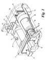
- Figure 1 shows a preferred embodiment of an electro-hydraulic actuator according to the present invention.
- the actuator has no external plumbing connections which are susceptible to freezing, breakage, leakage associated with tubing connections and hydraulic joints.
- the actuator is completely self-contained and uses internal cast flow paths to move fluid to and from the various operating components of the actuator.
- the actuator has no atmospheric vented reservoir and can be mounted in any orientation.
- the actuator preferably comprises a pump and motor assembly 8 including a gerotor positive displacement pump element 18 (not shown in Figure 1), plates to house the gerotor 19 and a motor 20 close coupled to the gerotor 19 to turn the gerotor 19 and create pumping action.
- a gerotor positive displacement pump element advantageously provides faster operational speeds than hydraulic units using a spur gear or a diaphragm pump.
- a pump end casing 7 provides a mount for the pump and motor assembly 8, solenoid valve 10 and optional solenoid valve 9, and also provides a mechanism for fluid transfer within the actuator including to and from solenoid valves 9 and 10 and the pump and motor assembly 8.
- the pump end casing preferably also includes a one-way check valve 11 to prevent back flow into the pump.
- the hydraulic piston assembly of the actuator preferably comprises piston return springs 1, piston/rack 5, internal guide rods 4, a splined output shaft 22, and output shaft connections 21 (see Figure 3).
- the output shaft connections 21 are connected to output pinion 6 and are concentrically surrounded by hydraulic pinion seals.
- Pinion 6 is connected to a device to be turned, such as a valve.
- the actuator of the present invention can also be used for operating a damper, louvre or other device which require a rotary motion to effect a change in operation.
- the hydraulic piston assembly is operated by fluid pressure entering the assembly from the pump end casing 7 through output port 23 preferably located in one of the internal guide rods 4 and into centre chamber 24 between piston/rack walls 25. As the pressure increases, the centre chamber 24 fills with fluid and presses piston/rack walls 25 outward against the action of return springs 1. Internal guide rods 4 keep the piston/rack 5 square to the pinion 6 during movement. As piston/rack walls 25 move outward, teeth 26 on the piston/rack 5 engaging corresponding teeth on the output shaft 22 turn the output shaft 22 and pinion 6 (shown in Figure 2a). The pinion 6 is connected to a valve (not shown) and the turning action of the pinion 6 is transmitted to a valve by any number of means known in the prior art.
- a limit switch end casing 12 houses limit switches 13 and connecting push rods 14 which monitor the piston position and control the actuator when it reaches full stroke.
- connecting push rods 14 are displaced toward the limit switch end casing 12 which activates the limit switches 13.
- the limit switches 13 then shut down the pump and motor. No external gearing, cams or rods are used.
- Conduit connections 15 and terminal strips 16 are also provided for wiring the motor, position control electronics, or for providing a drain port if desired.
- An in-line check valve 11 is positioned at the outlet of pump and motor assembly 8 to prevent back flow of fluid into the pump and motor assembly 8 when not operating (see Figures 1, 4 and 5).
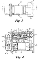
- fluid is pumped from the check valve 11 through flow path 27 to the hydraulic piston assembly and through port 23 (see Figure 4) in internal guide rod 4 to operate piston/rack 5 as discussed above with reference to Figure 4.
- Alternative flow path 28 leads to solenoid valve 29, the "fail-safe" solenoid valve (shown in a "closed” position).
- solenoid valve 29 In systems with only one solenoid valve, when the actuator is energized, solenoid valve 29 is closed, and hydraulic fluid flows only to the hydraulic piston assembly. If there is loss of power to the actuator, or the actuator is deenergized, solenoid valve 29 opens allowing the return springs 1 to force fluid to move out of the centre chamber 24 and rotate pinion 6 to the "fail-safe" position. The fluid forced out of the centre chamber 24 flows through paths 27 and 28 to path 30 (see Figure 5) into the hydraulic piston assembly and through port 34 (see Figure 4) into an outside chamber 35 as shown in Figure 4.
- the electro-hydraulic actuators of the present invention have two solenoid valves which operate independently from one another.
- solenoid valve 29 is used for "fail-safe" operation. In the event of power failure, or power shut off to the actuator, solenoid valve 29 opens and allows the return springs 1 to force the actuator into a "fail-safe" position. Means for signalling the solenoid valve 29 to open upon power failure are well known in the art.
- Positioning solenoid valve 31, as shown in Figure 5, is connected to flow path 27 by flow path 32, on either side of where flow path 28 connects to flow path 27.
- Positioning solenoid valve 31 is normally open and is used in conjunction with a positioning controller (not shown) mounted to the actuator for intermediate actuator positioning.
- Positioning solenoid valve 31 preferably has a smaller capacity than the "fail-safe" solenoid valve to allow for finer control of the speed and positioning of the actuator to avoid overshoot.
- the positioning solenoid valve 31 and fail-safe solenoid valve 29 are closed and remain closed until some further change in the system.
- the controller limits the power to the motor to that necessary to open the actuator to the particular position for which the controller is set.
- the check valve 11 maintains the required fluid pressure to hold the actuator at the desired position.
- the motor is started and the controller provides increased power to the motor to push more fluid into the centre chamber 24.
- the controller sends a signal to the positioning solenoid valve 31 to open the positioning solenoid valve 31 allowing the return springs 1 to force fluid to move out of the centre chamber 24 through paths 27 and 32 to path 30 and through port 34 into the hydraulic piston assembly in an outside chamber 35, outside of the rack/piston walls 25. See Figures 4 and 5.
- the positioning solenoid valve 31 is closed to maintain the actuator in the desired position.
- Figure 4 shows a top view of the internal flow paths as they are preferably contained within the actuator casing, with flow path 27, containing check valve 11, being located directly above flow path 30 (see also Figure 1), and flow paths 32 and 28 being located in the same vertical plane within the actuator casing.
- the positioning controller can be any one of various types of market-available positioning devices capable of controlling at voltages compatible with motor and solenoid requirements of an actuator according to the invention.
- the voltage requirements of a particular actuator according to the invention will vary depending on the size of power requirements of the valve and actuator.
Landscapes
- Engineering & Computer Science (AREA)
- Physics & Mathematics (AREA)
- Fluid Mechanics (AREA)
- Mechanical Engineering (AREA)
- General Engineering & Computer Science (AREA)
- Chemical & Material Sciences (AREA)
- Analytical Chemistry (AREA)
- Actuator (AREA)
- Fluid-Pressure Circuits (AREA)
- Magnetically Actuated Valves (AREA)
- Fluid-Driven Valves (AREA)
- Mechanically-Actuated Valves (AREA)
Claims (12)
- Elektrohydraulisches Betätigungsglied, aufweisend
ein Gehäuse des Betätigungsgliedes,
eine Kolben/Zahnstangenvorrichtung (5) innerhalb des Gehäuses mit Wänden (25), die hin- und hergehende lineare Bewegungen ausführen und zwischen sich eine mittlere Kammer (24) festlegen und innerhalb des Gehäuses zwei äußere Kammern (35),
eine mit der Kolben/Zahnstangenvorrichtung (5) in Verbindung stehende Abtriebswelle (22), die auf die linearen Bewegungen der Kolben/Zahnstangenvorrichtung (5) mit Rotationsbewegungen ansprechen kann,
eine federelastische Rückholvorrichtung (1) in jeder der beiden äußeren Kammern (35), die an den hin- und hergehenden Wänden (25) der Kolben/Zahnstangenvorrichtung (5) und an den inneren Enden des Gehäuses anliegt, wobei diese federelastische Rückholvorrichtung (1) die hin- und hergehenden Wände (25) der Kolben/Zahnstangenvorrichtung (5) zu einer geschlossenen Position hin vorspannt,
eine Pumpvorrichtung (8),
ein primärer Fließweg (27) für die Übertragung des Hydraulikmediums von der Pumpvorrichtung (8) zu einer ersten Austrittsöffnung (23) und in die mittlere Kammer (24), wobei das Hydraulikmedium in der mittleren Kammer (24) eine Expansion bewirkt und damit die Kolben/Zahnstangenvorrichtüng (5) zur Übertragung der linearen Bewegung auf die Abtriebswelle (22) veranlasst und
ein ausfallsicheres Magnetventilsystem mit einem an den primären Fließweg (27) angeschlossenen und von ihm ausgehenden sekundären Fließweg (28) zu einer zweiten Ausgangsöffnung (34) hin, die sich in mindestens eine der äußeren Kammern (35) öffnet und ein normalerweise offenes Magnetventil (29) im sekundären Fließweg (28), das einen Durchfluss durch den sekundären Fließweg (28) verhindert,
wobei sich nach einem Stromausfall des Betätigungsgliedes das ausfallsichere Magnetventil (29) öffnet und dadurch die federelastische Rückholvorrichtung (1) veranlasst, Hydraulikmedium aus der mittleren Kammer (24) hinaus und durch den primären Fließweg (27) und sekundären Fließweg (28) in mindestens eine der äußeren Kammern (35) zu drücken, so dass die Kolben/Zahnstangenvorrichtung (5) in eine geschlossene Position zurückbewegt und die Abtriebswelle (22) zu einer Rotationsbewegung veranlasst wird, dadurch gekennzeichnet, dass das Betätigungsglied eine in sich geschlossene Einheit mit internem primären und sekundären Fließweg (27, 28) und ohne externe Armaturenanschlüsse ist. - Elektrohydraulisches Betätigungsglied nach Anspruch 1, das ferner mindestens eine innere Führungsstange (4) zur Führung der linearen Bewegung der Kolben/Zahnstangenvorrichtung im Gehäuse aufweist.
- Elektrohydraulisches Betätigungsglied nach Anspruch 2, wobei mindestens eine der inneren Führungsstangen (4) die erste Austrittsöffnung (23) aus dem primären Fließweg (27) enthält und wobei das Medium, das durch den primären Fließweg (27) in die mittlere Kammer (24) hinein und aus ihr heraus gelangt, durch die mindestens eine innere Führungsstange (4) und durch die Austrittsöffnung (23) in der inneren Führungsstange (4) fließt.
- Elektrohydraulisches Betätigungsglied nach einem der vorstehenden Ansprüche, das ferner ein Magnetventilsystem zur Positionsregelung beinhaltet, welches einen dritten inneren Fließweg (32) einschließt, der von einem Anschluss am primären Fließweg (27) ausgehend zu der zweiten Austrittsöffnung (34) führt und in diesem dritten Fließweg (32) ein normalerweise offenes Magnetventil (31) zur Positionsregelung aufweist, das den Durchfluss durch den dritten Fließweg (32) verhindert, wobei das Magnetventil (31) mit Arbeitskontakt zur Positionsregelung für die teilweise Schließung der Kolben/Zahnstangenvorrichtung (5) mittels eines Positionsreglers geöffnet wird, wodurch die federelastische Rückholvorrichtung (1) Hydraulikmedium aus der mittleren Kammer (24) hinaus und durch den primären und sekundären Fließweg (27 und 32) in mindestens eine der äußeren Kammern (35) drücken und die Kolben/Zahnstangenvorrichtung (5) in eine teilweise geschlossene Position bewegen kann, wodurch der Positionsregler das Magnetventil (31) zur Positionsregelung schließt.
- Elektrohydraulisches Betätigungsglied nach Anspruch 4, wobei das Magnetventil (31) zur Positionsregelung eine kleinere Durchflusskapazität als das ausfallsichere Magnetventil (29) hat.
- Elektrohydraulisches Betätigungsglied nach einem der vorstehenden Ansprüche, wobei die Kolben/Zahnstangenvorrichtung (5) in der Lage ist, ihre lineare Bewegung in eine Rotationsbewegung der Abtriebswelle (22) bis zu 360 Grad umzusetzen.
- Elektrohydraulisches Betätigungsglied nach einem der vorstehenden Ansprüche, wobei die Pumpvorrichtung (8) eine Verdränger-Rotorpumpe (18) mit innenverzahntem Rotor beinhaltet.
- Elektrohydraulisches Betätigungsglied nach einem der vorstehenden Ansprüche, das eine Schubstange (14) zur Anzeige der Position der Kolben/Zahnstangenvorrichtung (5) beinhaltet und einen Grenzschalter (13) zum Abschalten des Pumpvorgangs der Pumpvorrichtung (8) wenn die Schubstange (14) anzeigt, dass die Kolben/Zahnstangenvorrichtung (5) vollständig geöffnet ist.
- Elektrohydraulisches Betätigungsglied nach einem der vorstehenden Ansprüche, das ferner ein am Auslass der Pumpvorrichtung (8) befindliches Rückschlagventil (11) zur Verhinderung eines Rückflusses in die Pumpvorrichtung (8) aufweist.
- Elektrohydraulisches Betätigungsglied nach einem der vorstehenden Ansprüche, wobei die Abtriebswelle (22) ein Ventil antreibt.
- Elektrohydraulisches Betätigungsglied nach einem der Ansprüche 1 bis 9, wobei die Abtriebswelle (22) eine Dämpfungseinrichtung oder eine Klappe antreibt.
- Elektrohydraulisches Betätigungsglied nach einem der vorstehenden Ansprüche, wobei die federelastische Rückholvorrichtung (1) Federn beinhaltet.
Applications Claiming Priority (2)
| Application Number | Priority Date | Filing Date | Title |
|---|---|---|---|
| US972443 | 1997-11-18 | ||
| US08/972,443 US5950427A (en) | 1997-11-18 | 1997-11-18 | Fail-safe electric hydraulic actuator |
Publications (3)
| Publication Number | Publication Date |
|---|---|
| EP0916853A2 EP0916853A2 (de) | 1999-05-19 |
| EP0916853A3 EP0916853A3 (de) | 2000-03-29 |
| EP0916853B1 true EP0916853B1 (de) | 2005-01-26 |
Family
ID=25519664
Family Applications (1)
| Application Number | Title | Priority Date | Filing Date |
|---|---|---|---|
| EP98309079A Expired - Lifetime EP0916853B1 (de) | 1997-11-18 | 1998-11-05 | Elektrohydraulisches Betätigungsglied |
Country Status (7)
| Country | Link |
|---|---|
| US (1) | US5950427A (de) |
| EP (1) | EP0916853B1 (de) |
| AR (1) | AR015483A1 (de) |
| BR (1) | BR9806381A (de) |
| CA (1) | CA2254336C (de) |
| DE (1) | DE69828740T2 (de) |
| GB (1) | GB2331332B (de) |
Families Citing this family (23)
| Publication number | Priority date | Publication date | Assignee | Title |
|---|---|---|---|---|
| DE19939497C2 (de) * | 1999-08-20 | 2001-09-27 | Samson Ag | Antrieb eines Stellventils mit Sensiereinheit zur Ventilpositionserfassung |
| US6439477B1 (en) * | 2000-02-03 | 2002-08-27 | Nelson Irrigation Corporation | Nutating sprinkler |
| FR2851306B1 (fr) | 2003-02-18 | 2006-08-04 | Giat Ind Sa | Generateur electro-hydraulique compact pour motorisation de tourelleau |
| ES2255036T3 (es) * | 2003-02-18 | 2006-06-16 | Giat Industries | Generador electrohidraulico compacto para motorizacion de torreta. |
| US6892534B2 (en) * | 2003-07-18 | 2005-05-17 | Young & Franklin Inc. | Electro-hydrostatic actuator with a failsafe system |
| US7156183B2 (en) | 2004-11-17 | 2007-01-02 | Fmc Technologies, Inc. | Electric hydraulic power unit and method of using same |
| US8118571B2 (en) * | 2005-03-31 | 2012-02-21 | Dana Automotive Systems Group, Llc | Actuator assembly |
| KR20080025366A (ko) * | 2005-04-29 | 2008-03-20 | 텐딕스 디벨롭먼트, 엘엘씨 | 래디얼 임펄스 엔진, 펌프 및 압축기 시스템과 관련 동작방법 |
| US7182310B2 (en) * | 2005-06-24 | 2007-02-27 | Shui-Ching Chen | Position return device for an open and close apparatus |
| US7377479B1 (en) * | 2006-11-28 | 2008-05-27 | Shui-Ching Chen | Position restoring apparatus for an open and close device |
| US20100242891A1 (en) * | 2008-10-30 | 2010-09-30 | Timber Dick | Radial impulse engine, pump, and compressor systems, and associated methods of operation |
| USD632366S1 (en) * | 2009-02-16 | 2011-02-08 | Air Torque S.P.A. | Fluid dynamic actuator |
| CN201909093U (zh) * | 2010-12-22 | 2011-07-27 | 济南高仕机械制造有限公司 | 一种压缩气体单作用执行器 |
| CN102678678B (zh) * | 2012-05-29 | 2014-12-24 | 特福隆集团有限公司 | 液压应急操作模块 |
| US9810245B2 (en) * | 2013-03-15 | 2017-11-07 | Habonim Industrial Valves & Actuators Ltd. | Spring return actuator |
| DE102013212493B3 (de) * | 2013-06-27 | 2014-09-25 | Schaeffler Technologies Gmbh & Co. Kg | Schaltbare Sperrvorrichtung, die eine Aktuatorik sowie einen Drehschieber einschließt |
| DE102013222644A1 (de) * | 2013-11-07 | 2015-05-07 | Schaeffler Technologies Gmbh & Co. Kg | Mehrstufig schaltbare Sperrvorrichtung mit einer Aktuatorik und Drehschiebern |
| USD960327S1 (en) * | 2019-01-22 | 2022-08-09 | Air Torque S.P.A. | Fluidodynamic actuator |
| US11421798B2 (en) * | 2019-09-13 | 2022-08-23 | Amit Shah | Electro-hydraulic actuator and valve arrangement comprising electro-hydraulic actuator |
| CN111059096B (zh) * | 2019-11-28 | 2020-11-27 | 同济大学 | 一种液压回中锁紧作动缸结构 |
| EP4067127B1 (de) * | 2021-03-31 | 2024-06-19 | BeijingWest Industries Co. Ltd. | Hydraulischer hub-aktuator für die höhenverstellung der achsverkleidung |
| US11851163B2 (en) | 2022-04-25 | 2023-12-26 | Hamilton Sundstrand Corporation | Hydraulically locking actuator configuration |
| CN116412188B (zh) * | 2023-02-23 | 2025-11-18 | 浙江大学高端装备研究院 | 超声波检测位置的带紧急关断的阀块与油缸一体式的eha |
Family Cites Families (25)
| Publication number | Priority date | Publication date | Assignee | Title |
|---|---|---|---|---|
| US837252A (en) * | 1905-07-26 | 1906-11-27 | John H Rose | Hydraulic motor. |
| US2134227A (en) * | 1935-05-24 | 1938-10-25 | Ippelsheim Lotte Forkardt Geb | Operating mechanism for chucks |
| US2534525A (en) * | 1947-07-14 | 1950-12-19 | James F Molloy | Closure operator |
| US2844127A (en) * | 1955-03-03 | 1958-07-22 | Steiner Carl | Fluid pressure torque converter |
| GB1171618A (en) * | 1966-03-05 | 1969-11-26 | Norbo Engineering Ltd | Rotary actuators |
| US3456561A (en) * | 1967-09-25 | 1969-07-22 | William Laikam Jr | Air pressure actuated cylinder unit |
| US3572032A (en) * | 1968-07-18 | 1971-03-23 | William M Terry | Immersible electrohydraulic failsafe valve operator |
| US3982725A (en) * | 1974-06-27 | 1976-09-28 | Keystone International, Inc. | Valve actuator |
| US4054155A (en) * | 1974-08-26 | 1977-10-18 | Hill Ralph W | Hydraulic actuated control valve |
| US4087073A (en) * | 1976-04-26 | 1978-05-02 | Otis Engineering Corporation | Safety valve with a hydraulic actuator |
| US4065094A (en) * | 1976-08-19 | 1977-12-27 | Parker-Hannifin Corporation | Hydraulic actuator |
| US4132071A (en) | 1977-10-11 | 1979-01-02 | Hills-Mccanna Company | Electro-hydraulic controlled valve actuator system |
| US4203351A (en) * | 1978-02-14 | 1980-05-20 | Griesel B.V. | Fluid motor actuator for rotating a shaft back and forth |
| SE414815B (sv) * | 1978-11-24 | 1980-08-18 | Wire Matic Regler Ab | Pneumatiskt manoverdon |
| US4256017A (en) * | 1979-04-05 | 1981-03-17 | The Bendix Corporation | Differential area electrohydraulic doser actuator |
| US4295630A (en) * | 1979-08-09 | 1981-10-20 | Greer Hydraulics, Incorporated | Fail-safe actuator and hydraulic system incorporating the same |
| US4757684A (en) * | 1981-04-08 | 1988-07-19 | Wright John J | Fail-safe electric actuator |
| CH661331A5 (de) * | 1983-08-25 | 1987-07-15 | Fischer Ag Georg | Ventileinrichtung mit einer fernsteuerbaren betaetigungseinrichtung. |
| GB8529601D0 (en) * | 1985-12-02 | 1986-01-08 | Lotus Group Plc | Vehicle with front & rear wheel steering |
| IT1196937B (it) * | 1986-07-08 | 1988-11-25 | Giovanni Trevisan | Struttura di molla precompressa, particolarmente studiata per attuatori semirotanti a comando pneumatico, a semplice effetto |
| EP0433347B1 (de) * | 1988-09-10 | 1993-06-16 | ZF FRIEDRICHSHAFEN Aktiengesellschaft | Hilfskraftlenkung, insbesondere für kraftfahrzeuge |
| US5440969A (en) * | 1994-03-09 | 1995-08-15 | Shin; Wan-Sheng | Cylinder-operated and spring-loaded driving mechanism for a ball valve |
| US5615595A (en) * | 1995-06-30 | 1997-04-01 | Bettis Corporation | Tandem cylinder control |
| GB2309747A (en) * | 1996-02-03 | 1997-08-06 | Hytek Tech Int | Fluid-pressure-operated actuators |
| JP3850946B2 (ja) | 1996-04-22 | 2006-11-29 | 株式会社名南製作所 | ベニヤ単板の加熱装置 |
-
1997
- 1997-11-18 US US08/972,443 patent/US5950427A/en not_active Expired - Lifetime
-
1998
- 1998-11-05 GB GB9824092A patent/GB2331332B/en not_active Expired - Lifetime
- 1998-11-05 EP EP98309079A patent/EP0916853B1/de not_active Expired - Lifetime
- 1998-11-05 DE DE69828740T patent/DE69828740T2/de not_active Expired - Lifetime
- 1998-11-18 CA CA002254336A patent/CA2254336C/en not_active Expired - Fee Related
- 1998-11-18 BR BR9806381-2A patent/BR9806381A/pt not_active IP Right Cessation
- 1998-11-18 AR ARP980105835A patent/AR015483A1/es active IP Right Grant
Also Published As
| Publication number | Publication date |
|---|---|
| DE69828740T2 (de) | 2005-12-29 |
| BR9806381A (pt) | 2002-07-09 |
| GB2331332B (en) | 2000-02-23 |
| EP0916853A2 (de) | 1999-05-19 |
| GB2331332A (en) | 1999-05-19 |
| CA2254336C (en) | 2003-01-21 |
| GB9824092D0 (en) | 1998-12-30 |
| US5950427A (en) | 1999-09-14 |
| AR015483A1 (es) | 2001-05-02 |
| EP0916853A3 (de) | 2000-03-29 |
| CA2254336A1 (en) | 1999-05-18 |
| DE69828740D1 (de) | 2005-03-03 |
Similar Documents
| Publication | Publication Date | Title |
|---|---|---|
| EP0916853B1 (de) | Elektrohydraulisches Betätigungsglied | |
| US5487527A (en) | Valve actuator | |
| CN102834617B (zh) | 在配件上流体操纵的伺服驱动装置 | |
| US4480811A (en) | Fail-safe actuator device | |
| US6957533B1 (en) | Operation device | |
| CN112789412A (zh) | 用于在水下使用的具有液压伺服驱动装置的液压系统 | |
| WO2009070358A1 (en) | Dual redundant servovalve | |
| US11067197B2 (en) | Subsea shut-off device | |
| US3675420A (en) | Valve actuator | |
| US3084513A (en) | Electrohydraulic actuator | |
| CN213332683U (zh) | 具有液压电动驱动机构的调节阀 | |
| EP3755929B1 (de) | Wegeventil | |
| KR101703375B1 (ko) | 유압모터용 제어장치 및 유압모터 조립체 | |
| KR100337684B1 (ko) | 유압식으로 작동될 수 있는 전기자 | |
| ES2380141T3 (es) | Conjunto constructivo eléctricamente controlable con una conexión hidráulica | |
| JPS634075B2 (de) | ||
| CA1329052C (en) | Fluid-driven pump | |
| KR100988699B1 (ko) | 모듈화된 직동력 고응답 유압 엑츄에이터 시스템 | |
| CN223868276U (zh) | 一种单作用多回转电液执行装置 | |
| US3112654A (en) | Self-locking fluid operated valve actuating mechanism | |
| KR200328483Y1 (ko) | 전기 유압 일체형 유압 엑츄에이터 | |
| US12560182B1 (en) | Hydraulic isolation cylinder-based system | |
| EP3992505A1 (de) | Vorrichtung zur steuerung eines ventils | |
| HK1045352B (en) | Operation device | |
| HK1045352C (en) | Operation device |
Legal Events
| Date | Code | Title | Description |
|---|---|---|---|
| PUAI | Public reference made under article 153(3) epc to a published international application that has entered the european phase |
Free format text: ORIGINAL CODE: 0009012 |
|
| AK | Designated contracting states |
Kind code of ref document: A2 Designated state(s): DE FR IT NL SE |
|
| AX | Request for extension of the european patent |
Free format text: AL;LT;LV;MK;RO;SI |
|
| PUAL | Search report despatched |
Free format text: ORIGINAL CODE: 0009013 |
|
| AK | Designated contracting states |
Kind code of ref document: A3 Designated state(s): AT BE CH CY DE DK ES FI FR GB GR IE IT LI LU MC NL PT SE |
|
| AX | Request for extension of the european patent |
Free format text: AL;LT;LV;MK;RO;SI |
|
| 17P | Request for examination filed |
Effective date: 20000519 |
|
| AKX | Designation fees paid |
Free format text: DE FR IT NL SE |
|
| 17Q | First examination report despatched |
Effective date: 20021104 |
|
| GRAP | Despatch of communication of intention to grant a patent |
Free format text: ORIGINAL CODE: EPIDOSNIGR1 |
|
| GRAS | Grant fee paid |
Free format text: ORIGINAL CODE: EPIDOSNIGR3 |
|
| GRAA | (expected) grant |
Free format text: ORIGINAL CODE: 0009210 |
|
| AK | Designated contracting states |
Kind code of ref document: B1 Designated state(s): DE FR IT NL SE |
|
| PG25 | Lapsed in a contracting state [announced via postgrant information from national office to epo] |
Ref country code: NL Free format text: LAPSE BECAUSE OF FAILURE TO SUBMIT A TRANSLATION OF THE DESCRIPTION OR TO PAY THE FEE WITHIN THE PRESCRIBED TIME-LIMIT Effective date: 20050126 Ref country code: IT Free format text: LAPSE BECAUSE OF FAILURE TO SUBMIT A TRANSLATION OF THE DESCRIPTION OR TO PAY THE FEE WITHIN THE PRESCRIBED TIME-LIMIT;WARNING: LAPSES OF ITALIAN PATENTS WITH EFFECTIVE DATE BEFORE 2007 MAY HAVE OCCURRED AT ANY TIME BEFORE 2007. THE CORRECT EFFECTIVE DATE MAY BE DIFFERENT FROM THE ONE RECORDED. Effective date: 20050126 |
|
| REF | Corresponds to: |
Ref document number: 69828740 Country of ref document: DE Date of ref document: 20050303 Kind code of ref document: P |
|
| REG | Reference to a national code |
Ref country code: SE Ref legal event code: TRGR |
|
| NLV1 | Nl: lapsed or annulled due to failure to fulfill the requirements of art. 29p and 29m of the patents act | ||
| PG25 | Lapsed in a contracting state [announced via postgrant information from national office to epo] |
Ref country code: SE Free format text: LAPSE BECAUSE OF NON-PAYMENT OF DUE FEES Effective date: 20051106 |
|
| PLBE | No opposition filed within time limit |
Free format text: ORIGINAL CODE: 0009261 |
|
| STAA | Information on the status of an ep patent application or granted ep patent |
Free format text: STATUS: NO OPPOSITION FILED WITHIN TIME LIMIT |
|
| ET | Fr: translation filed | ||
| 26N | No opposition filed |
Effective date: 20051027 |
|
| EUG | Se: european patent has lapsed | ||
| PG25 | Lapsed in a contracting state [announced via postgrant information from national office to epo] |
Ref country code: FR Free format text: LAPSE BECAUSE OF NON-PAYMENT OF DUE FEES Effective date: 20060731 |
|
| REG | Reference to a national code |
Ref country code: FR Ref legal event code: ST Effective date: 20060731 |
|
| PGFP | Annual fee paid to national office [announced via postgrant information from national office to epo] |
Ref country code: DE Payment date: 20171129 Year of fee payment: 20 |
|
| REG | Reference to a national code |
Ref country code: DE Ref legal event code: R071 Ref document number: 69828740 Country of ref document: DE |