EP0916741B1 - Fours à refroidissement rapide pour bandes métalliques - Google Patents
Fours à refroidissement rapide pour bandes métalliques Download PDFInfo
- Publication number
- EP0916741B1 EP0916741B1 EP98402476A EP98402476A EP0916741B1 EP 0916741 B1 EP0916741 B1 EP 0916741B1 EP 98402476 A EP98402476 A EP 98402476A EP 98402476 A EP98402476 A EP 98402476A EP 0916741 B1 EP0916741 B1 EP 0916741B1
- Authority
- EP
- European Patent Office
- Prior art keywords
- exchanger
- gas
- strip
- duct
- section
- Prior art date
- Legal status (The legal status is an assumption and is not a legal conclusion. Google has not performed a legal analysis and makes no representation as to the accuracy of the status listed.)
- Expired - Lifetime
Links
- 239000002184 metal Substances 0.000 title claims abstract description 8
- 238000001816 cooling Methods 0.000 title claims description 28
- 239000007789 gas Substances 0.000 claims abstract description 40
- 239000001257 hydrogen Substances 0.000 claims abstract description 13
- 229910052739 hydrogen Inorganic materials 0.000 claims abstract description 13
- 239000000112 cooling gas Substances 0.000 claims abstract description 11
- UFHFLCQGNIYNRP-UHFFFAOYSA-N Hydrogen Chemical compound [H][H] UFHFLCQGNIYNRP-UHFFFAOYSA-N 0.000 claims abstract description 9
- 239000000203 mixture Substances 0.000 claims abstract description 7
- XLYOFNOQVPJJNP-UHFFFAOYSA-N water Substances O XLYOFNOQVPJJNP-UHFFFAOYSA-N 0.000 claims abstract description 7
- 238000011144 upstream manufacturing Methods 0.000 claims abstract description 5
- 238000009434 installation Methods 0.000 claims description 13
- 238000010438 heat treatment Methods 0.000 claims description 7
- 230000001960 triggered effect Effects 0.000 claims description 7
- IJGRMHOSHXDMSA-UHFFFAOYSA-N Atomic nitrogen Chemical compound N#N IJGRMHOSHXDMSA-UHFFFAOYSA-N 0.000 claims description 6
- 238000011282 treatment Methods 0.000 claims description 4
- 230000008878 coupling Effects 0.000 claims description 3
- 238000010168 coupling process Methods 0.000 claims description 3
- 238000005859 coupling reaction Methods 0.000 claims description 3
- 150000002431 hydrogen Chemical class 0.000 claims description 3
- 229910052757 nitrogen Inorganic materials 0.000 claims description 3
- 230000004044 response Effects 0.000 claims description 3
- 230000005611 electricity Effects 0.000 claims 4
- 230000000903 blocking effect Effects 0.000 abstract 2
- 230000003134 recirculating effect Effects 0.000 abstract 2
- 230000003213 activating effect Effects 0.000 abstract 1
- 230000008602 contraction Effects 0.000 description 4
- 238000000137 annealing Methods 0.000 description 3
- 238000007664 blowing Methods 0.000 description 3
- 230000004907 flux Effects 0.000 description 3
- 238000001514 detection method Methods 0.000 description 2
- 239000000463 material Substances 0.000 description 2
- 238000011084 recovery Methods 0.000 description 2
- 241000196324 Embryophyta Species 0.000 description 1
- 241001249696 Senna alexandrina Species 0.000 description 1
- 230000015556 catabolic process Effects 0.000 description 1
- 238000010276 construction Methods 0.000 description 1
- 230000001627 detrimental effect Effects 0.000 description 1
- 238000005246 galvanizing Methods 0.000 description 1
- 238000012423 maintenance Methods 0.000 description 1
- 238000004519 manufacturing process Methods 0.000 description 1
- 238000000034 method Methods 0.000 description 1
- 238000005507 spraying Methods 0.000 description 1
- 238000007669 thermal treatment Methods 0.000 description 1
- 239000005028 tinplate Substances 0.000 description 1
Images


Classifications
-
- C—CHEMISTRY; METALLURGY
- C23—COATING METALLIC MATERIAL; COATING MATERIAL WITH METALLIC MATERIAL; CHEMICAL SURFACE TREATMENT; DIFFUSION TREATMENT OF METALLIC MATERIAL; COATING BY VACUUM EVAPORATION, BY SPUTTERING, BY ION IMPLANTATION OR BY CHEMICAL VAPOUR DEPOSITION, IN GENERAL; INHIBITING CORROSION OF METALLIC MATERIAL OR INCRUSTATION IN GENERAL
- C23C—COATING METALLIC MATERIAL; COATING MATERIAL WITH METALLIC MATERIAL; SURFACE TREATMENT OF METALLIC MATERIAL BY DIFFUSION INTO THE SURFACE, BY CHEMICAL CONVERSION OR SUBSTITUTION; COATING BY VACUUM EVAPORATION, BY SPUTTERING, BY ION IMPLANTATION OR BY CHEMICAL VAPOUR DEPOSITION, IN GENERAL
- C23C2/00—Hot-dipping or immersion processes for applying the coating material in the molten state without affecting the shape; Apparatus therefor
- C23C2/26—After-treatment
- C23C2/261—After-treatment in a gas atmosphere, e.g. inert or reducing atmosphere
-
- F—MECHANICAL ENGINEERING; LIGHTING; HEATING; WEAPONS; BLASTING
- F27—FURNACES; KILNS; OVENS; RETORTS
- F27B—FURNACES, KILNS, OVENS OR RETORTS IN GENERAL; OPEN SINTERING OR LIKE APPARATUS
- F27B9/00—Furnaces through which the charge is moved mechanically, e.g. of tunnel type; Similar furnaces in which the charge moves by gravity
- F27B9/28—Furnaces through which the charge is moved mechanically, e.g. of tunnel type; Similar furnaces in which the charge moves by gravity for treating continuous lengths of work
-
- B—PERFORMING OPERATIONS; TRANSPORTING
- B05—SPRAYING OR ATOMISING IN GENERAL; APPLYING FLUENT MATERIALS TO SURFACES, IN GENERAL
- B05C—APPARATUS FOR APPLYING FLUENT MATERIALS TO SURFACES, IN GENERAL
- B05C3/00—Apparatus in which the work is brought into contact with a bulk quantity of liquid or other fluent material
- B05C3/02—Apparatus in which the work is brought into contact with a bulk quantity of liquid or other fluent material the work being immersed in the liquid or other fluent material
- B05C3/12—Apparatus in which the work is brought into contact with a bulk quantity of liquid or other fluent material the work being immersed in the liquid or other fluent material for treating work of indefinite length
- B05C3/125—Apparatus in which the work is brought into contact with a bulk quantity of liquid or other fluent material the work being immersed in the liquid or other fluent material for treating work of indefinite length the work being a web, band, strip or the like
-
- C—CHEMISTRY; METALLURGY
- C21—METALLURGY OF IRON
- C21D—MODIFYING THE PHYSICAL STRUCTURE OF FERROUS METALS; GENERAL DEVICES FOR HEAT TREATMENT OF FERROUS OR NON-FERROUS METALS OR ALLOYS; MAKING METAL MALLEABLE, e.g. BY DECARBURISATION OR TEMPERING
- C21D9/00—Heat treatment, e.g. annealing, hardening, quenching or tempering, adapted for particular articles; Furnaces therefor
- C21D9/52—Heat treatment, e.g. annealing, hardening, quenching or tempering, adapted for particular articles; Furnaces therefor for wires; for strips ; for rods of unlimited length
- C21D9/54—Furnaces for treating strips or wire
- C21D9/56—Continuous furnaces for strip or wire
- C21D9/561—Continuous furnaces for strip or wire with a controlled atmosphere or vacuum
-
- C—CHEMISTRY; METALLURGY
- C21—METALLURGY OF IRON
- C21D—MODIFYING THE PHYSICAL STRUCTURE OF FERROUS METALS; GENERAL DEVICES FOR HEAT TREATMENT OF FERROUS OR NON-FERROUS METALS OR ALLOYS; MAKING METAL MALLEABLE, e.g. BY DECARBURISATION OR TEMPERING
- C21D9/00—Heat treatment, e.g. annealing, hardening, quenching or tempering, adapted for particular articles; Furnaces therefor
- C21D9/52—Heat treatment, e.g. annealing, hardening, quenching or tempering, adapted for particular articles; Furnaces therefor for wires; for strips ; for rods of unlimited length
- C21D9/54—Furnaces for treating strips or wire
- C21D9/56—Continuous furnaces for strip or wire
- C21D9/573—Continuous furnaces for strip or wire with cooling
-
- C—CHEMISTRY; METALLURGY
- C23—COATING METALLIC MATERIAL; COATING MATERIAL WITH METALLIC MATERIAL; CHEMICAL SURFACE TREATMENT; DIFFUSION TREATMENT OF METALLIC MATERIAL; COATING BY VACUUM EVAPORATION, BY SPUTTERING, BY ION IMPLANTATION OR BY CHEMICAL VAPOUR DEPOSITION, IN GENERAL; INHIBITING CORROSION OF METALLIC MATERIAL OR INCRUSTATION IN GENERAL
- C23C—COATING METALLIC MATERIAL; COATING MATERIAL WITH METALLIC MATERIAL; SURFACE TREATMENT OF METALLIC MATERIAL BY DIFFUSION INTO THE SURFACE, BY CHEMICAL CONVERSION OR SUBSTITUTION; COATING BY VACUUM EVAPORATION, BY SPUTTERING, BY ION IMPLANTATION OR BY CHEMICAL VAPOUR DEPOSITION, IN GENERAL
- C23C2/00—Hot-dipping or immersion processes for applying the coating material in the molten state without affecting the shape; Apparatus therefor
- C23C2/34—Hot-dipping or immersion processes for applying the coating material in the molten state without affecting the shape; Apparatus therefor characterised by the shape of the material to be treated
- C23C2/36—Elongated material
- C23C2/40—Plates; Strips
-
- F—MECHANICAL ENGINEERING; LIGHTING; HEATING; WEAPONS; BLASTING
- F27—FURNACES; KILNS; OVENS; RETORTS
- F27D—DETAILS OR ACCESSORIES OF FURNACES, KILNS, OVENS OR RETORTS, IN SO FAR AS THEY ARE OF KINDS OCCURRING IN MORE THAN ONE KIND OF FURNACE
- F27D21/00—Arrangement of monitoring devices; Arrangement of safety devices
-
- F—MECHANICAL ENGINEERING; LIGHTING; HEATING; WEAPONS; BLASTING
- F27—FURNACES; KILNS; OVENS; RETORTS
- F27B—FURNACES, KILNS, OVENS OR RETORTS IN GENERAL; OPEN SINTERING OR LIKE APPARATUS
- F27B9/00—Furnaces through which the charge is moved mechanically, e.g. of tunnel type; Similar furnaces in which the charge moves by gravity
- F27B9/12—Furnaces through which the charge is moved mechanically, e.g. of tunnel type; Similar furnaces in which the charge moves by gravity with special arrangements for preheating or cooling the charge
- F27B2009/124—Cooling
-
- F—MECHANICAL ENGINEERING; LIGHTING; HEATING; WEAPONS; BLASTING
- F27—FURNACES; KILNS; OVENS; RETORTS
- F27D—DETAILS OR ACCESSORIES OF FURNACES, KILNS, OVENS OR RETORTS, IN SO FAR AS THEY ARE OF KINDS OCCURRING IN MORE THAN ONE KIND OF FURNACE
- F27D21/00—Arrangement of monitoring devices; Arrangement of safety devices
- F27D2021/0007—Monitoring the pressure
-
- F—MECHANICAL ENGINEERING; LIGHTING; HEATING; WEAPONS; BLASTING
- F27—FURNACES; KILNS; OVENS; RETORTS
- F27D—DETAILS OR ACCESSORIES OF FURNACES, KILNS, OVENS OR RETORTS, IN SO FAR AS THEY ARE OF KINDS OCCURRING IN MORE THAN ONE KIND OF FURNACE
- F27D21/00—Arrangement of monitoring devices; Arrangement of safety devices
- F27D2021/0057—Security or safety devices, e.g. for protection against heat, noise, pollution or too much duress; Ergonomic aspects
- F27D2021/0092—Security or safety devices, e.g. for protection against heat, noise, pollution or too much duress; Ergonomic aspects against a jam in the transport line or a production interruption
Definitions
- the present invention relates to improvements made to rapid cooling for strip materials and more particularly for metal bands.
- These ovens can be part of, in particular, treatments such as for example heat treatments of metallic products in strip, in particular for galvanizing, annealing, production of tinplate, etc.
- the recycled atmospheric gas is blown onto the metal strip in continuous circulation, after cooling in particular using gas / water heat exchangers, the composition of the atmosphere, and more particularly its high hydrogen content, making it possible to obtain very rapid cooling rates of the order of 100 ° C. per second.
- the installations therefore comprise a circuit of recirculation ducts for the atmosphere gas N 2 , H 2 , one or more fans for ensuring the continuous circulation of this atmospheric gas in the recirculation ducts and gas / water exchangers.
- the present invention solves the problems mentioned above by providing means allowing, on the one hand, to prevent the passage of atmospheric gas through of the exchanger (s), i.e. too rapid cooling of this gas atmosphere, which prevents a sudden depression in the oven in case of breakage of the strip and on the other hand to stop, in a very short time, that is to say less than five seconds, recirculation of atmospheric gas into the cooling chamber fast, during a wave break in a compensator or during a power outage power supply.
- the actuators preferably tires, are triggered by a sensor detecting any variation of the belt tension.
- the actuators are triggered via a sensor detecting any variation in pressure in the rapid cooling chamber.
- means are furthermore designed and produced to so as to allow the rotation of the fan (s) to be stopped in a very short time, these means can be achieved by coupling the fan to a generator on which it is engaged either in the event of a wave break in a compensator, or in the event of power cut.
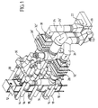
- This oven or chamber cooling is generally part of an installation comprising a plurality of strip material processing stations, this installation being for example of the type described in EP-0 795 616 mentioned above.
- the metal strip 12 circulates continuously, this strip coming in general of other treatment enclosures for example heat treatments, maintenance, annealing, etc.
- Rapid cooling is obtained by spraying the strip 12, in continuous circulation, with a jet of gas of atmosphere N 2 , H 2 , containing, as explained above, a large proportion of hydrogen, greater than 15% and up to 50%.
- This atmospheric gas is projected onto the lateral faces of the strip 12 by means of nozzles such as 14 supplied by sheaths such as 16 and it is taken up using sheaths such as 18 which open parallel to the plane of the strip 12 in the rapid cooling chamber 10.
- the circulation of the atmospheric gas is obtained using a fan such as 20, driven by an electric motor 22, the blowing of the atmospheric gas being carried out by by means of a collecting sheath 24 supplying the sheaths 14 while the recovery of this atmosphere gas is carried out by means of the collecting sheaths 26, 26 ′ supplied by the sheaths 18.
- the installation also comprises, in a known manner, exchangers 28, 28 ', of preferably gas / water type which are housed in enclosures designated in their together by the reference 32, respectively 32 ', on which the ducts 26, 26 'for atmospheric gas, in order to cool the latter, after circulation in the rapid cooling chamber 10 and before recovery by the fan 20 and blowing through ducts 24 and 16.
- exchangers 28, 28 ' of preferably gas / water type which are housed in enclosures designated in their together by the reference 32, respectively 32 ', on which the ducts 26, 26 'for atmospheric gas, in order to cool the latter, after circulation in the rapid cooling chamber 10 and before recovery by the fan 20 and blowing through ducts 24 and 16.
- the various sheaths 16, 18, 24, 26, 26 'in include compensators 30, produced in the form of a series of waves allowing the assembly sheaths to expand.
- FIGS 3 and 4 schematically illustrate the improvements brought about by the invention.
- FIGs 3 and 4 respectively represent in plan and in section, an enclosure, such as 32 or 32 '( Figures 1 and 2) receiving a heat exchanger such as 28, 28 'in Figures 1 and 2.
- the direction of recirculation of the cooling gas has been represented by arrow F, this gas coming from the ducts 18 being sucked through the sheath 26, by the fan 20.
- the passage to through the exchanger 28 is effected by the section of the enclosure designated by the reference A, this section being described below as the main passage section.
- this main passage section A comprises, upstream of the exchanger 28, a register shown schematically at 34 and provision is made for derived passage sections, designated by the references B also provided with registers such as 36, 36 'through which the circulation flow of the cooling gas, so that it no longer passes through exchangers such as 28, 28 ', as will be explained below (arrows f).
- the different registers 34, 36, 36 ' are controlled by actuators, preferably of the pneumatic type, such as 38, 38 ' having a very short response time, that is to say less than 5 seconds.
- the triggering of these actuators allows either to interrupt the circulation of the cooling gas through the section of main passage A, i.e. through exchangers such as 28, 28 'and divert this circulation through branch sections B (register 34 closed and registers 36, 36 'open) or, to interrupt all circulation of the gas from cooling through passage sections A and B (registers 34, 36, 36 ' closed).
- the first phenomenon that is to say a break in the strip
- a tape tension sensor any variation of this voltage from a setpoint causing the tripping of actuators controlling the closing of the main passage section A and the opening of the branch passage sections B.
- a pressure sensor positioned for example in the rapid cooling 10, any vacuum detection in this chamber immediately driving the actuators as mentioned above.
- the latter can also be used to detect a wave break in a compensator 30 in order to immediately trigger the closing of the section of passage A, the derived sections B being kept closed as indicated in the table above.
- any conventional means can be used to control the actuators 38 in power supply interruptions, including switches tripping by power failure or fault in order to cause a immediate closure of the main passage section A, the passage sections derivative B remaining closed.
- the present invention it is also possible to provide means allowing to stop in a very short time, the rotation of the fan 20 for example by coupling to a generator to which it is engaged either in the event of a wave break a compensator 30, ie in the event of a power cut.
Landscapes
- Engineering & Computer Science (AREA)
- Chemical & Material Sciences (AREA)
- Mechanical Engineering (AREA)
- Materials Engineering (AREA)
- Organic Chemistry (AREA)
- Metallurgy (AREA)
- Physics & Mathematics (AREA)
- Crystallography & Structural Chemistry (AREA)
- Thermal Sciences (AREA)
- General Engineering & Computer Science (AREA)
- Chemical Kinetics & Catalysis (AREA)
- Heat Treatment Of Strip Materials And Filament Materials (AREA)
- Heat Treatments In General, Especially Conveying And Cooling (AREA)
- Waste-Gas Treatment And Other Accessory Devices For Furnaces (AREA)
Description
- une section de passage principal par laquelle s'effectue la circulation du gaz de refroidissement au travers desdits échangeurs, cette section de passage étant munie d'un registre en amont du ou desdits échangeurs ;
- des sections de passage dérivé, permettant de dévier le flux du gaz de refroidissement en cas de fermeture de la section de passage principal, pour que ce flux ne traverse pas le ou lesdits échangeurs, lesdites sections de passage dérivé étant munies de registres et,
- des actionneurs, à temps de réponse très court, c'est-à-dire inférieurs à cinq secondes, ces derniers étant déclenchés par l'intermédiaire de moyens de détection de la rupture de la bande, de la rupture d'une onde de compensateur et d'une coupure de l'alimentation électrique.
- Les figures 1 et 2 sont des vues en perspective illustrant un exemple de réalisation d'un four de refroidissement rapide avec ses gaines de souflage et de recirculation du gaz d'atmosphère.
- La figure 3 est une vue en plan, schématique illustrant les perfectionnements apportés par la présente invention et,
- La figure 4 est une coupe selon IV-IV de la figure 3.
| DESIGNATION | SENS DE PASSAGE DU GAZ DE REFROIDISSEMENT | ||
| Section de passage | B | A | B |
| cas de marche normale | Fermé | Ouvert | Fermé |
| Cas du premier phénomène | Déclenchement de l'ouverture des registres 36, 36' | Déclenchement de la fermeture du registre 34 | Déclenchement de l'ouverture des registres 36, 36' |
| Cas du deuxième phénomène | Fermé | Déclenchement de la fermeture du registre 34 | Fermé |
| Cas du troisième phénomène | Fermé | Déclenchement de la fermeture du registre 34 | Fermé |
- de ne pas augmenter les pertes de charges du circuit de recirculation du gaz de refroidissement ;
- de ne pas perturber le flux gazeux au travers de l'échangeur 28 durant la marche normale et,
- de ne pas gêner le bon fonctionnement du ventilateur.
Claims (7)
- Four à refroidissement rapide, pouvant faire partie d'une installation comportant divers postes de traitement, notamment de traitement thermique de produits en bande, dans lequel circule en continu une bande métallique (12), le refroidissement rapide étant obtenu par projection sur la bande d'un jet de gaz d'atmosphère constitué d'un mélange d'azote et d'hydrogène présentant une teneur en hydrogène supérieure à 15%, et de préférence voisine de 50%, la recirculation du gaz d'atmosphère étant assurée à l'aide d'un circuit de gaines de recirculation (16, 18, 26, 26', 24) comportant au moins un ventilateur (20) ainsi qu'au moins un échangeur gaz/eau (28, 28') les différentes gaines comportant des compensateurs (30) réalisés sous la forme d'une série d'ondes permettant à l'ensemble des gaines de se dilater, ce four (10) étant caractérisé en ce que l'enceinte (32, 32') dans laquelle sont logés le ou lesdits échangeurs (28, 28') et sur laquelle débouchent les gaines de recirculation (16, 18, 26, 26', 24) du gaz d'atmosphère comporte :une section de passage principal (A) par laquelle s'effectue la circulation du gaz de refroidissement au travers desdits échangeurs, cette section de passage (A) étant munie d'un registre (34) en amont du ou desdits échangeurs ;des sections de passage dérivé (B) , permettant de dévier le flux du gaz de refroidissement en cas de fermeture de la section de passage principal (A), pour que ce flux ne traverse pas le ou lesdits échangeurs, lesdites sections de passage dérivé étant munies de registres (36, 36') et,des actionneurs (38, 38'), à temps de réponse très court, c'est-à-dire inférieur à cinq secondes, ces derniers étant déclenchés par l'intermédiaire de moyens de détection de la rupture de la bande, de la rupture d'une onde de compensateur et d'une coupure de l'alimentation électrique
- Four selon la revendication 1 caractérisé en ce que lesdits actionneurs (38, 38'), de préférence du type pneumatique, sont déclenchés par l'intermédiaire d'un capteur détectant toute variation de la tension de la bande.
- Four selon la revendication 1 caractérisé en ce que lesdits actionneurs (38, 38') sont déclenchés par l'intermédiaire d'un capteur détectant toute variation de la pression dans la chambre de refroidissement rapide (10).
- Four selon la revendication 1 caractérisé en ce que l'on prévoit des moyens pour déclencher les actionneurs (38) commandant le registre (34) prévu sur la section de passage principal (A) en cas d'interruption de l'alimentation électrique, de manière à provoquer une fermeture immédiate de ladite section de passage principal, les sections de passage dérivé (B) restant fermées.
- Four selon la revendication 4 caractérisé en ce que lesdits moyens pour déclencher les actionneurs (38) en cas d'interruption de l'alimentation électrique sont réalisés sous la forme de commutateurs à déclenchement par coupure ou défaut de courant.
- Four selon l'une quelconque des revendications précédentes caractérisé en ce que l'on prévoit des moyens permettant d'arrêter dans un temps très court, la rotation du ventilateur (20).
- Four selon la revendication 6 caractérisé en ce que lesdits moyens permettant d'arrêter la rotation du ventilateur (20) en un temps très court consistent à l' accoupler à un générateur sur lequel il est embrayé soit en cas d'une rupture d'onde d'un compensateur 30, soit en cas de coupure de l'alimentation électrique.
Applications Claiming Priority (2)
| Application Number | Priority Date | Filing Date | Title |
|---|---|---|---|
| FR9712906 | 1997-10-15 | ||
| FR9712906A FR2769695B1 (fr) | 1997-10-15 | 1997-10-15 | Perfectionnements apportes aux fours a refroidissement rapide pour bandes metalliques |
Publications (2)
| Publication Number | Publication Date |
|---|---|
| EP0916741A1 EP0916741A1 (fr) | 1999-05-19 |
| EP0916741B1 true EP0916741B1 (fr) | 2002-01-16 |
Family
ID=9512260
Family Applications (1)
| Application Number | Title | Priority Date | Filing Date |
|---|---|---|---|
| EP98402476A Expired - Lifetime EP0916741B1 (fr) | 1997-10-15 | 1998-10-06 | Fours à refroidissement rapide pour bandes métalliques |
Country Status (9)
| Country | Link |
|---|---|
| US (1) | US6092389A (fr) |
| EP (1) | EP0916741B1 (fr) |
| JP (1) | JP3323820B2 (fr) |
| KR (1) | KR100581983B1 (fr) |
| CN (1) | CN1088113C (fr) |
| AT (1) | ATE212071T1 (fr) |
| DE (2) | DE69803157T2 (fr) |
| ES (1) | ES2131493T3 (fr) |
| FR (1) | FR2769695B1 (fr) |
Families Citing this family (3)
| Publication number | Priority date | Publication date | Assignee | Title |
|---|---|---|---|---|
| US7308669B2 (en) * | 2005-05-18 | 2007-12-11 | International Business Machines Corporation | Use of redundant routes to increase the yield and reliability of a VLSI layout |
| CN103074480A (zh) * | 2011-10-26 | 2013-05-01 | 苏州新长光热能科技有限公司 | 一种热处理炉用可控内循环冷却系统 |
| CN110184449A (zh) * | 2019-06-24 | 2019-08-30 | 湖北钱潮精密件有限公司 | 热处理回火炉落料口双开关控制装置及方法 |
Family Cites Families (7)
| Publication number | Priority date | Publication date | Assignee | Title |
|---|---|---|---|---|
| IT946124B (it) * | 1970-12-01 | 1973-05-21 | Nippon Steel Corp | Apparecchio per il trattamento continuo di lamiera di acciaio |
| US4398700A (en) * | 1982-09-29 | 1983-08-16 | Midland-Ross Corporation | Annealing furnace with an improved cooling section |
| DE3583212D1 (de) * | 1984-11-08 | 1991-07-18 | Mitsubishi Heavy Ind Ltd | Verfahren und vorrichtung zum erwaermen eines metallbandes in einem durchlaufgluehofen. |
| BR8504750A (pt) * | 1984-11-14 | 1986-07-22 | Nippon Steel Corp | Aparelho de revestimento de tira para um forno de recozimento continuo |
| US5137586A (en) * | 1991-01-02 | 1992-08-11 | Klink James H | Method for continuous annealing of metal strips |
| JP5339242B2 (ja) | 2008-03-12 | 2013-11-13 | 株式会社リコー | 二光子吸収材料とその用途 |
| JP5677603B2 (ja) | 2012-11-26 | 2015-02-25 | 東京エレクトロン株式会社 | 基板洗浄システム、基板洗浄方法および記憶媒体 |
-
1997
- 1997-10-15 FR FR9712906A patent/FR2769695B1/fr not_active Expired - Lifetime
-
1998
- 1998-10-06 EP EP98402476A patent/EP0916741B1/fr not_active Expired - Lifetime
- 1998-10-06 DE DE69803157T patent/DE69803157T2/de not_active Expired - Fee Related
- 1998-10-06 ES ES98402476T patent/ES2131493T3/es not_active Expired - Lifetime
- 1998-10-06 AT AT98402476T patent/ATE212071T1/de not_active IP Right Cessation
- 1998-10-06 DE DE0916741T patent/DE916741T1/de active Pending
- 1998-10-12 JP JP28911798A patent/JP3323820B2/ja not_active Expired - Fee Related
- 1998-10-13 KR KR1019980042659A patent/KR100581983B1/ko not_active Expired - Fee Related
- 1998-10-14 US US09/172,043 patent/US6092389A/en not_active Expired - Fee Related
- 1998-10-15 CN CN98121346A patent/CN1088113C/zh not_active Expired - Fee Related
Also Published As
| Publication number | Publication date |
|---|---|
| DE916741T1 (de) | 1999-11-04 |
| KR19990037035A (ko) | 1999-05-25 |
| ATE212071T1 (de) | 2002-02-15 |
| CN1216323A (zh) | 1999-05-12 |
| DE69803157T2 (de) | 2002-08-14 |
| EP0916741A1 (fr) | 1999-05-19 |
| FR2769695B1 (fr) | 1999-12-31 |
| US6092389A (en) | 2000-07-25 |
| DE69803157D1 (de) | 2002-02-21 |
| CN1088113C (zh) | 2002-07-24 |
| ES2131493T1 (es) | 1999-08-01 |
| ES2131493T3 (es) | 2002-05-01 |
| KR100581983B1 (ko) | 2006-09-27 |
| FR2769695A1 (fr) | 1999-04-16 |
| JP3323820B2 (ja) | 2002-09-09 |
| JPH11193422A (ja) | 1999-07-21 |
Similar Documents
| Publication | Publication Date | Title |
|---|---|---|
| EP2035588B1 (fr) | Dispositif de sécurisation d'un four équipé d'un chauffage et d'un refroidissement rapides fonctionnant sous atmosphère contrôlée. | |
| US5614110A (en) | Varying protective gas composition between piercing and cutting with plasma torch | |
| EP0822733A1 (fr) | Dispositif de chauffage par induction et installation de traitement thermique en continu comportant un tel dispositif | |
| JP2001203211A (ja) | 水素アニール処理方法及びその装置 | |
| CN1408028A (zh) | 加热金属带的方法及其装置 | |
| US6833155B2 (en) | Apparatus and method for processing a substrate | |
| EP0916741A1 (fr) | Fours à refroidissement rapide pour bandes métalliques | |
| EP0913658B2 (fr) | Système de sécurité pour fours ayant un refroidissement à gaz pour bande métallique | |
| EP0879897B2 (fr) | Procédé de recuit d'un substrat métallique au défilé | |
| JP2007528940A (ja) | 薄膜及び薄膜デバイスを製造するための装置及び方法 | |
| JPH07231109A (ja) | 光起電力素子及びその形成方法及びその形成装置 | |
| US6413081B2 (en) | Method for purging a furnace and furnace assembly | |
| US5265788A (en) | Bonding machine with oxidization preventive means | |
| EP2795217A1 (fr) | Dispositif de refroidissement d'une embouchure d'un four tubulaire rotatif par soufflage d'air frais | |
| KR100399793B1 (ko) | 수소 가스 연소 방법 및 이를 수행하기 위한 시스템 | |
| US2284658A (en) | Gas blast electric circuit breaker | |
| US3735592A (en) | Apparatus for protection of a gas jet generator | |
| JP5508036B2 (ja) | 連続式光輝焼鈍方法 | |
| FR2745416A1 (fr) | Amenee de courant haute tension mixte | |
| JP3222245B2 (ja) | 光起電力素子用半導体積層膜の連続形成装置及び方法 | |
| JP3297487B2 (ja) | 光起電力素子及びその形成方法及びその形成装置 | |
| JPH1079354A (ja) | 熱処理炉のガス排出方法およびガス排出装置 | |
| JP3093503B2 (ja) | 光起電力素子及びその形成方法及びその形成装置 | |
| JPH03278522A (ja) | 拡散処理装置 | |
| KR19980049287A (ko) | 열간압연중 강판 표면 산화피막의 동결장치 및 그 방법 |
Legal Events
| Date | Code | Title | Description |
|---|---|---|---|
| PUAI | Public reference made under article 153(3) epc to a published international application that has entered the european phase |
Free format text: ORIGINAL CODE: 0009012 |
|
| AK | Designated contracting states |
Kind code of ref document: A1 Designated state(s): AT BE DE ES FI GB IT LU NL SE |
|
| AX | Request for extension of the european patent |
Free format text: AL;LT;LV;MK;RO;SI |
|
| ITCL | It: translation for ep claims filed |
Representative=s name: BARZANO' E ZANARDO MILANO S.P.A. |
|
| GBC | Gb: translation of claims filed (gb section 78(7)/1977) | ||
| 17P | Request for examination filed |
Effective date: 19990531 |
|
| REG | Reference to a national code |
Ref country code: ES Ref legal event code: BA2A Ref document number: 2131493 Country of ref document: ES Kind code of ref document: T1 |
|
| TCAT | At: translation of patent claims filed | ||
| TCNL | Nl: translation of patent claims filed | ||
| DET | De: translation of patent claims | ||
| AKX | Designation fees paid |
Free format text: AT BE DE ES FI GB IT LU NL SE |
|
| GRAG | Despatch of communication of intention to grant |
Free format text: ORIGINAL CODE: EPIDOS AGRA |
|
| GRAG | Despatch of communication of intention to grant |
Free format text: ORIGINAL CODE: EPIDOS AGRA |
|
| GRAH | Despatch of communication of intention to grant a patent |
Free format text: ORIGINAL CODE: EPIDOS IGRA |
|
| 17Q | First examination report despatched |
Effective date: 20010522 |
|
| GRAH | Despatch of communication of intention to grant a patent |
Free format text: ORIGINAL CODE: EPIDOS IGRA |
|
| GRAA | (expected) grant |
Free format text: ORIGINAL CODE: 0009210 |
|
| REG | Reference to a national code |
Ref country code: GB Ref legal event code: IF02 |
|
| AK | Designated contracting states |
Kind code of ref document: B1 Designated state(s): AT BE DE ES FI GB IT LU NL SE |
|
| REF | Corresponds to: |
Ref document number: 212071 Country of ref document: AT Date of ref document: 20020215 Kind code of ref document: T |
|
| GBT | Gb: translation of ep patent filed (gb section 77(6)(a)/1977) |
Effective date: 20020117 |
|
| REF | Corresponds to: |
Ref document number: 69803157 Country of ref document: DE Date of ref document: 20020221 |
|
| REG | Reference to a national code |
Ref country code: ES Ref legal event code: FG2A Ref document number: 2131493 Country of ref document: ES Kind code of ref document: T3 |
|
| PLBE | No opposition filed within time limit |
Free format text: ORIGINAL CODE: 0009261 |
|
| STAA | Information on the status of an ep patent application or granted ep patent |
Free format text: STATUS: NO OPPOSITION FILED WITHIN TIME LIMIT |
|
| 26N | No opposition filed | ||
| PGFP | Annual fee paid to national office [announced via postgrant information from national office to epo] |
Ref country code: LU Payment date: 20070928 Year of fee payment: 10 |
|
| PGFP | Annual fee paid to national office [announced via postgrant information from national office to epo] |
Ref country code: FI Payment date: 20070924 Year of fee payment: 10 |
|
| PGFP | Annual fee paid to national office [announced via postgrant information from national office to epo] |
Ref country code: GB Payment date: 20070925 Year of fee payment: 10 |
|
| PGFP | Annual fee paid to national office [announced via postgrant information from national office to epo] |
Ref country code: SE Payment date: 20070925 Year of fee payment: 10 Ref country code: NL Payment date: 20070924 Year of fee payment: 10 Ref country code: ES Payment date: 20071008 Year of fee payment: 10 |
|
| PGFP | Annual fee paid to national office [announced via postgrant information from national office to epo] |
Ref country code: AT Payment date: 20070924 Year of fee payment: 10 Ref country code: IT Payment date: 20071018 Year of fee payment: 10 |
|
| PGFP | Annual fee paid to national office [announced via postgrant information from national office to epo] |
Ref country code: DE Payment date: 20081030 Year of fee payment: 11 |
|
| EUG | Se: european patent has lapsed | ||
| GBPC | Gb: european patent ceased through non-payment of renewal fee |
Effective date: 20081006 |
|
| NLV4 | Nl: lapsed or anulled due to non-payment of the annual fee |
Effective date: 20090501 |
|
| PG25 | Lapsed in a contracting state [announced via postgrant information from national office to epo] |
Ref country code: NL Free format text: LAPSE BECAUSE OF NON-PAYMENT OF DUE FEES Effective date: 20090501 Ref country code: FI Free format text: LAPSE BECAUSE OF NON-PAYMENT OF DUE FEES Effective date: 20081006 |
|
| PG25 | Lapsed in a contracting state [announced via postgrant information from national office to epo] |
Ref country code: IT Free format text: LAPSE BECAUSE OF NON-PAYMENT OF DUE FEES Effective date: 20081006 Ref country code: AT Free format text: LAPSE BECAUSE OF NON-PAYMENT OF DUE FEES Effective date: 20081006 |
|
| PG25 | Lapsed in a contracting state [announced via postgrant information from national office to epo] |
Ref country code: GB Free format text: LAPSE BECAUSE OF NON-PAYMENT OF DUE FEES Effective date: 20081006 |
|
| REG | Reference to a national code |
Ref country code: ES Ref legal event code: FD2A Effective date: 20081007 |
|
| PG25 | Lapsed in a contracting state [announced via postgrant information from national office to epo] |
Ref country code: ES Free format text: LAPSE BECAUSE OF NON-PAYMENT OF DUE FEES Effective date: 20081007 |
|
| PG25 | Lapsed in a contracting state [announced via postgrant information from national office to epo] |
Ref country code: LU Free format text: LAPSE BECAUSE OF NON-PAYMENT OF DUE FEES Effective date: 20081006 |
|
| PG25 | Lapsed in a contracting state [announced via postgrant information from national office to epo] |
Ref country code: SE Free format text: LAPSE BECAUSE OF NON-PAYMENT OF DUE FEES Effective date: 20081007 Ref country code: DE Free format text: LAPSE BECAUSE OF NON-PAYMENT OF DUE FEES Effective date: 20100501 |
|
| PGFP | Annual fee paid to national office [announced via postgrant information from national office to epo] |
Ref country code: BE Payment date: 20100927 Year of fee payment: 13 |
|
| BERE | Be: lapsed |
Owner name: FIVE STEIN Effective date: 20111031 |
|
| PG25 | Lapsed in a contracting state [announced via postgrant information from national office to epo] |
Ref country code: BE Free format text: LAPSE BECAUSE OF NON-PAYMENT OF DUE FEES Effective date: 20111031 |