EP0916557A2 - Rétracteur de boucle - Google Patents
Rétracteur de boucle Download PDFInfo
- Publication number
- EP0916557A2 EP0916557A2 EP98121130A EP98121130A EP0916557A2 EP 0916557 A2 EP0916557 A2 EP 0916557A2 EP 98121130 A EP98121130 A EP 98121130A EP 98121130 A EP98121130 A EP 98121130A EP 0916557 A2 EP0916557 A2 EP 0916557A2
- Authority
- EP
- European Patent Office
- Prior art keywords
- piston
- transmission means
- tensioner according
- lock tensioner
- lock
- Prior art date
- Legal status (The legal status is an assumption and is not a legal conclusion. Google has not performed a legal analysis and makes no representation as to the accuracy of the status listed.)
- Granted
Links
Images
Classifications
-
- B—PERFORMING OPERATIONS; TRANSPORTING
- B60—VEHICLES IN GENERAL
- B60R—VEHICLES, VEHICLE FITTINGS, OR VEHICLE PARTS, NOT OTHERWISE PROVIDED FOR
- B60R22/00—Safety belts or body harnesses in vehicles
- B60R22/18—Anchoring devices
- B60R22/195—Anchoring devices with means to tension the belt in an emergency, e.g. means of the through-anchor or splitted reel type
Definitions
- the invention relates to a lock tensioner for a next to Vehicle seat belt buckle, which is a piston / cylinder unit with a cylinder and a piston arranged inside it and an elastically deflectable connecting the piston and the buckle Train transmission means includes.
- a flexible traction cable as a means of transmission between the piston of the Tensioner and the buckle used.
- the flexible pull rope also serves as an anchor for the buckle and allows for seat belt an alignment of the buckle for approximation to the webbing course. The lower the bending moment of the pull rope, the better the adjustment the orientation of the buckle to the webbing course. At the Inserting the tongue into the buckle proves to be too little Bending resistance moment of the anchoring, however, as disadvantageous, because the buckle can easily move sideways.
- the invention creates a lock tensioner that is optimally aligned of the buckle allowed.
- the belt buckle gives way when inserted the tongue does not point away from the vehicle seat, but still fits the webbing course with the seat belt on easy on.
- a lock tensioner of the type mentioned kind this is achieved according to the invention in that the train transmission means a deflection of the belt buckle towards the vehicle seat opposes less resistance than a deflection from Vehicle seat away.
- the adjustment of the belt buckle together with the train transmission means the course of the seat belt can be improved in that the train transmission means a deflection of the belt buckle in the vehicle longitudinal direction, that is towards the front or rear of the vehicle, provides less resistance than deflection towards the vehicle seat.
- the Lock tensioner on an elastically deflectable support part on the connects the side facing away from the vehicle seat to the train transmission means and supports it towards away from the vehicle seat.
- the bending moment of resistance of the tension transmission means in the direction away from the vehicle seat which makes it too easy to avoid the seat belt buckle prevented when inserting the tongue.
- it can Belt buckle adjusted to the vehicle seat without the application of greater forces become. This is a requirement when the seat belt is fastened for an optimal webbing course.
- the support part and the train transmission means to couple with each other is to use both as leaf springs train and attach them to each other so that a Leaf spring assembly results.
- the attachment of the piston to the leaf spring or on the leaf spring assembly is preferably done by pressing the Piston or part of the piston on one end of the tension transmission means.
- a particularly stable connection between the piston and Train transmission means results from the provision of recesses in the Tension transmission means into which the pressed piston or the pressed Part of the piston penetrates at least partially. To this This results in a positive connection.
- the train transmission means and / or the support part as a leaf spring package be trained.
- the lock tensioner can have a circular cylindrical cross section Cylinder or an oval cross-section cylinder and one have appropriately shaped pistons. Also a rectangular cylinder is conceivable.
- the shape of the cylinder should be chosen so that in particular a lock tensioner results in a small space occupies.
- the shape of the cylinder should also be the cross-sectional shape of the train transmission means, i.e. if at Example provided a traction transmission means elongated in cross section the cylinder can also be elongated in cross section, for example, oval or rectangular.
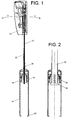
- a belt buckle 10 which has a tension transmission means 12 is coupled to a lock tensioner.
- Lock tensioner has a piston / cylinder unit that directly or is anchored indirectly to the vehicle floor.
- One inside the cylinder 14 displaceably arranged piston is fixed to the train transmission means 12 connected.
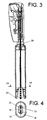
- the piston is in the illustrated embodiment formed in two parts and consists of an inner part 16 and a surrounding this inner part 16, releasably connected to it outer part 18.
- the inner part 16 can be a cone with a round, or as can be seen in Fig. 4, for space-saving accommodation of the Cross section of elongated transmission means 12 with an oval cross section be.
- Preferred materials for part 16 are aluminum and brass.
- the one open on the side facing away from the buckle Cylinder 14 has a stop 20 at the lower end thereof Inner diameter larger than that of the inner part 16, but smaller than that of the outer part 18.
- the train transmission means 12 which in the illustrated embodiment is designed as a leaf spring package, nestles on the side facing away from the vehicle seat another leaf spring, the serves as a support part 22.
- the leaf spring assembly is, as in Figure 1 can be seen with its wider sides the adjustment directions X and Y facing. By dimensioning and material selection of the Leaf spring pack can set the bending resistance torque as desired become.
- the support member 22 is only with the inner part 16 of the Belt tensioner connected, but not with the belt buckle 10 like that Train transmission means 12.
- Both the train transmission means 12 and the support part 22 have a plurality of recesses at its piston end 24 and a toothing 26 on their narrow outer sides, as can be seen in Figure 2.
- the inner part 16 of the piston is open the train transmission means 12 and the support member 22 pressed. Here the pressed-on part 16 penetrates into the recesses 24 and between adjacent teeth, so that there is a positive connection results.
- the lock tensioner also has a damping device. This is on the belt buckle-side end wall of the cylinder 14 a the train transmission means 12 and the support member 22 surrounding sleeve 28 attached.
- a preferred material for the sleeve 28 is aluminum. she can be used even when the lock tensioner is not activated pressure and gas tight on the train transmission means 12 and the support member 22 be pressed on.
- the vehicle occupant can use the tongue of the seat belt Slightly insert it into the buckle 10 because the support part 22 the position of the belt anchorage, which is caused by the tension transmission means 12 is formed in the y direction, i.e. away from the vehicle seat, stabilized, which prevents the belt buckle 10 from moving sideways.
- the compliance of the train transmission means 12 can therefore be designed so large that at belt can adjust an optimal webbing course.
- a propellant charge is generated in the conventional manner of the cylinder 14 ignited, whereby the parts 18 and 16 of the Piston and the support part 22 coupled thereto, the train transmission means 12 and the buckle 10 are moved down.
- the belt buckle 10 Towards the end of the tensioning path, the belt buckle 10 abuts the sleeve 28 and plastically deforms it, which absorbs some of the energy and voltage peaks are reduced.
- the piston has approximately when the Sleeve 28 is completely plastically compressed, the lower end of the Cylinder 14 reached.
- the inner part 16 detaches from the outer part 18 so that the part 18 of the train transmission means 12 and the belt buckle 10 is decoupled. This allows each other decoupled parts are braked and damped separately, creating a less space is required.
- the penalty path is through the Stop of part 18 limited to the lower stop 20 during the then moving the train transmission means 12 and the Belt buckle 10, these are delayed.
Landscapes
- Engineering & Computer Science (AREA)
- Mechanical Engineering (AREA)
- Automotive Seat Belt Assembly (AREA)
- Lubricants (AREA)
- Devices For Conveying Motion By Means Of Endless Flexible Members (AREA)
Applications Claiming Priority (2)
| Application Number | Priority Date | Filing Date | Title |
|---|---|---|---|
| DE29720213U DE29720213U1 (de) | 1997-11-14 | 1997-11-14 | Schloßstraffer |
| DE29720213U | 1997-11-14 |
Publications (3)
| Publication Number | Publication Date |
|---|---|
| EP0916557A2 true EP0916557A2 (fr) | 1999-05-19 |
| EP0916557A3 EP0916557A3 (fr) | 2001-05-30 |
| EP0916557B1 EP0916557B1 (fr) | 2004-01-21 |
Family
ID=8048626
Family Applications (1)
| Application Number | Title | Priority Date | Filing Date |
|---|---|---|---|
| EP98121130A Expired - Lifetime EP0916557B1 (fr) | 1997-11-14 | 1998-11-10 | Rétracteur de boucle |
Country Status (5)
| Country | Link |
|---|---|
| US (1) | US6155727A (fr) |
| EP (1) | EP0916557B1 (fr) |
| JP (1) | JPH11208416A (fr) |
| DE (2) | DE29720213U1 (fr) |
| ES (1) | ES2214673T3 (fr) |
Families Citing this family (14)
| Publication number | Priority date | Publication date | Assignee | Title |
|---|---|---|---|---|
| DE10052688A1 (de) * | 2000-10-24 | 2002-05-23 | Takata Europa Vehicle Safety T | Sicherheitsgurtvorrichtung |
| KR100369045B1 (ko) * | 2000-11-30 | 2003-01-24 | 현대자동차주식회사 | 자동차의 시트벨트버클앗세이 |
| KR100378543B1 (ko) * | 2000-12-06 | 2003-03-29 | 델파이 오토모티브 시스템스 성우 주식회사 | 자동차 시트벨트용 버클장치의 회동수단 |
| JP2003054360A (ja) | 2001-06-06 | 2003-02-26 | Takata Corp | シートベルト装置 |
| DE20208808U1 (de) * | 2002-06-06 | 2002-10-17 | TRW Occupant Restraint Systems GmbH & Co. KG, 73553 Alfdorf | Vorrichtung zum Straffen eines Sicherheitsgurts |
| EP1396398B1 (fr) | 2002-09-04 | 2006-06-21 | TAKATA-PETRI (Ulm) GmbH | Prétensionneur de boucle de ceinture de sécurité |
| DE10356569B4 (de) * | 2003-12-04 | 2006-07-06 | Autoliv Development Ab | Gurtschlosseinheit |
| US7658443B2 (en) * | 2005-12-07 | 2010-02-09 | Chrysler Group Llc | Inboard buckle attachment for a four-way seat |
| DE202008006330U1 (de) | 2007-06-15 | 2008-07-17 | Autoliv Development Ab | Schlossstraffer für einen Kraftfahrzeug-Sicherheitsgurt mit Aufschlagdämpfer |
| DE102008026872A1 (de) * | 2008-06-05 | 2009-12-10 | Trw Automotive Gmbh | Positioniervorrichtung |
| KR101209960B1 (ko) * | 2010-03-08 | 2012-12-07 | 현대자동차주식회사 | 시트 높이 조절장치와 연동하는 차량의 쉴드 커버 어셈블리 |
| KR101176787B1 (ko) * | 2010-11-23 | 2012-08-24 | 주식회사 디비아이 | 프리텐셔너 |
| DE102011108349A1 (de) * | 2011-07-25 | 2013-01-31 | Trw Automotive Gmbh | Straffer für einen Sicherheitsgurt |
| DE102011114497B4 (de) * | 2011-09-29 | 2013-08-29 | Autoliv Development Ab | Gurtschloss für eine Sicherheitsgurteinrichtung eines Kraftfahrzeugs |
Citations (3)
| Publication number | Priority date | Publication date | Assignee | Title |
|---|---|---|---|---|
| DE4224699A1 (de) * | 1992-07-25 | 1994-01-27 | Euwe Eugen Wexler Gmbh | Kunststoffgelenk zur gelenkigen Verbindung zweier Bauteile |
| DE29608210U1 (de) * | 1996-05-06 | 1996-09-12 | Trw Occupant Restraint Systems Gmbh, 73551 Alfdorf | Linearantrieb für ein Fahrzeuginsassen-Rückhaltesystem |
| DE29706024U1 (de) * | 1997-04-04 | 1997-07-31 | Trw Occupant Restraint Systems Gmbh, 73551 Alfdorf | Schloßstraffer für ein Sicherheitsgurtsystem |
Family Cites Families (5)
| Publication number | Priority date | Publication date | Assignee | Title |
|---|---|---|---|---|
| US4934030A (en) * | 1985-01-15 | 1990-06-19 | East/West Industries | Projection for use as a restraining tooth in a belt restraint assembly |
| US5607185A (en) * | 1993-11-26 | 1997-03-04 | Nippondenso Co., Ltd. | Belt tightener for seat belt |
| US5568940A (en) * | 1994-07-27 | 1996-10-29 | Trw Vehicle Safety Systems Inc. | Belt tightener for a vehicle safety belt system |
| US5531479A (en) * | 1995-01-20 | 1996-07-02 | Trw Vehicle Safety Systems Inc. | Vehicle seat belt restraint system |
| DE29607362U1 (de) * | 1996-04-23 | 1996-08-22 | Trw Occupant Restraint Systems Gmbh, 73551 Alfdorf | Sicherheitsgurtsystem |
-
1997
- 1997-11-14 DE DE29720213U patent/DE29720213U1/de not_active Expired - Lifetime
-
1998
- 1998-11-10 EP EP98121130A patent/EP0916557B1/fr not_active Expired - Lifetime
- 1998-11-10 DE DE59810624T patent/DE59810624D1/de not_active Expired - Fee Related
- 1998-11-10 ES ES98121130T patent/ES2214673T3/es not_active Expired - Lifetime
- 1998-11-12 US US09/190,089 patent/US6155727A/en not_active Expired - Fee Related
- 1998-11-13 JP JP10323977A patent/JPH11208416A/ja active Pending
Patent Citations (3)
| Publication number | Priority date | Publication date | Assignee | Title |
|---|---|---|---|---|
| DE4224699A1 (de) * | 1992-07-25 | 1994-01-27 | Euwe Eugen Wexler Gmbh | Kunststoffgelenk zur gelenkigen Verbindung zweier Bauteile |
| DE29608210U1 (de) * | 1996-05-06 | 1996-09-12 | Trw Occupant Restraint Systems Gmbh, 73551 Alfdorf | Linearantrieb für ein Fahrzeuginsassen-Rückhaltesystem |
| DE29706024U1 (de) * | 1997-04-04 | 1997-07-31 | Trw Occupant Restraint Systems Gmbh, 73551 Alfdorf | Schloßstraffer für ein Sicherheitsgurtsystem |
Also Published As
| Publication number | Publication date |
|---|---|
| EP0916557A3 (fr) | 2001-05-30 |
| ES2214673T3 (es) | 2004-09-16 |
| DE59810624D1 (de) | 2004-02-26 |
| US6155727A (en) | 2000-12-05 |
| DE29720213U1 (de) | 1998-01-02 |
| JPH11208416A (ja) | 1999-08-03 |
| EP0916557B1 (fr) | 2004-01-21 |
Similar Documents
| Publication | Publication Date | Title |
|---|---|---|
| DE102006053563B4 (de) | Gurtstraffer für ein Sicherheitsgurtsystem | |
| DE19882814C2 (de) | Gurtstraffer | |
| EP1232916B1 (fr) | Prétensionneur de ceinture de sécurité | |
| EP0873919B1 (fr) | Prétendeur pour ceinture de sécurité | |
| DE69402817T3 (de) | Aufroller für ein Gurtschloss | |
| DE10105500B4 (de) | Vorrichtung zum Straffen eines in einem Fahrzeugfond angeordneten Dreipunktsicherheitsgurtes | |
| EP0916557B1 (fr) | Rétracteur de boucle | |
| EP0780272A2 (fr) | Entraînement linéaire pour un tendeur de ceinture de sécurité | |
| EP0649778A1 (fr) | Installation d'un filet de sécurité | |
| DE4136623A1 (de) | Gurtstraffer fuer fahrzeug-sicherheitsgurtsysteme | |
| EP0557864A1 (fr) | Convertisseur d'énergie dans un système de retenue pour occupants de véhicule | |
| DE4117405A1 (de) | Sicherheitsgurt | |
| EP0422408B1 (fr) | Dispositif tendeur pour systèmes de retenue à ceinture de sécurité dans des véhicules | |
| EP0148747B1 (fr) | Système de ceinture de sécurité | |
| EP0889812B1 (fr) | Tendeur pour ceinture de securite | |
| DE19602916A1 (de) | Vorrichtung zum Verhindern einer Bewegungsumkehr und/oder des Herausziehens eines Gurtschlosses | |
| DE2258063A1 (de) | Hohlbauteil, insbesondere fuer kraftfahrzeuge | |
| DE60025984T2 (de) | Einrichtung zum Schutz der Insassen | |
| DE69503707T2 (de) | Gurtstraffer | |
| DE10010379A1 (de) | Sicherheitsgurtsystem | |
| DE102004023394B4 (de) | Schlosszunge für ein Sicherheitsgurtsystem | |
| EP0844153B1 (fr) | Rétracteur de boucle | |
| DE19641224B4 (de) | Antriebsvorrichtung, insbesondere zum Straffen eines Sicherheitsgurtes in einem Kraftfahrzeug | |
| DE19927513C2 (de) | Vorrichtung zum Straffen eines Fahrzeugsicherheitsgurtes | |
| DE19957794C2 (de) | Sicherheitsgurtanordnung bei Fahrzeugen |
Legal Events
| Date | Code | Title | Description |
|---|---|---|---|
| PUAI | Public reference made under article 153(3) epc to a published international application that has entered the european phase |
Free format text: ORIGINAL CODE: 0009012 |
|
| AK | Designated contracting states |
Kind code of ref document: A2 Designated state(s): DE ES FR GB IT |
|
| AX | Request for extension of the european patent |
Free format text: AL;LT;LV;MK;RO;SI |
|
| PUAL | Search report despatched |
Free format text: ORIGINAL CODE: 0009013 |
|
| AK | Designated contracting states |
Kind code of ref document: A3 Designated state(s): AT BE CH CY DE DK ES FI FR GB GR IE IT LI LU MC NL PT SE |
|
| AX | Request for extension of the european patent |
Free format text: AL;LT;LV;MK;RO;SI |
|
| 17P | Request for examination filed |
Effective date: 20010823 |
|
| AKX | Designation fees paid |
Free format text: DE ES FR GB IT |
|
| 17Q | First examination report despatched |
Effective date: 20021002 |
|
| GRAH | Despatch of communication of intention to grant a patent |
Free format text: ORIGINAL CODE: EPIDOS IGRA |
|
| GRAS | Grant fee paid |
Free format text: ORIGINAL CODE: EPIDOSNIGR3 |
|
| GRAA | (expected) grant |
Free format text: ORIGINAL CODE: 0009210 |
|
| AK | Designated contracting states |
Kind code of ref document: B1 Designated state(s): DE ES FR GB IT |
|
| REG | Reference to a national code |
Ref country code: GB Ref legal event code: FG4D Free format text: NOT ENGLISH |
|
| REF | Corresponds to: |
Ref document number: 59810624 Country of ref document: DE Date of ref document: 20040226 Kind code of ref document: P |
|
| GBT | Gb: translation of ep patent filed (gb section 77(6)(a)/1977) |
Effective date: 20040310 |
|
| REG | Reference to a national code |
Ref country code: ES Ref legal event code: FG2A Ref document number: 2214673 Country of ref document: ES Kind code of ref document: T3 |
|
| ET | Fr: translation filed | ||
| PG25 | Lapsed in a contracting state [announced via postgrant information from national office to epo] |
Ref country code: GB Free format text: LAPSE BECAUSE OF NON-PAYMENT OF DUE FEES Effective date: 20041110 |
|
| PG25 | Lapsed in a contracting state [announced via postgrant information from national office to epo] |
Ref country code: ES Free format text: LAPSE BECAUSE OF NON-PAYMENT OF DUE FEES Effective date: 20041111 |
|
| PLBE | No opposition filed within time limit |
Free format text: ORIGINAL CODE: 0009261 |
|
| STAA | Information on the status of an ep patent application or granted ep patent |
Free format text: STATUS: NO OPPOSITION FILED WITHIN TIME LIMIT |
|
| 26N | No opposition filed |
Effective date: 20041022 |
|
| GBPC | Gb: european patent ceased through non-payment of renewal fee |
Effective date: 20041110 |
|
| PG25 | Lapsed in a contracting state [announced via postgrant information from national office to epo] |
Ref country code: FR Free format text: LAPSE BECAUSE OF NON-PAYMENT OF DUE FEES Effective date: 20050729 |
|
| REG | Reference to a national code |
Ref country code: FR Ref legal event code: ST |
|
| PG25 | Lapsed in a contracting state [announced via postgrant information from national office to epo] |
Ref country code: IT Free format text: LAPSE BECAUSE OF NON-PAYMENT OF DUE FEES Effective date: 20051110 |
|
| REG | Reference to a national code |
Ref country code: ES Ref legal event code: FD2A Effective date: 20041111 |
|
| PGFP | Annual fee paid to national office [announced via postgrant information from national office to epo] |
Ref country code: DE Payment date: 20071130 Year of fee payment: 10 |
|
| PG25 | Lapsed in a contracting state [announced via postgrant information from national office to epo] |
Ref country code: DE Free format text: LAPSE BECAUSE OF NON-PAYMENT OF DUE FEES Effective date: 20090603 |