EP0916419B1 - Usinage de tôle sans enlèvement de matière, par étirage - Google Patents
Usinage de tôle sans enlèvement de matière, par étirage Download PDFInfo
- Publication number
- EP0916419B1 EP0916419B1 EP98120549A EP98120549A EP0916419B1 EP 0916419 B1 EP0916419 B1 EP 0916419B1 EP 98120549 A EP98120549 A EP 98120549A EP 98120549 A EP98120549 A EP 98120549A EP 0916419 B1 EP0916419 B1 EP 0916419B1
- Authority
- EP
- European Patent Office
- Prior art keywords
- sheet
- blades
- thickness
- calibration opening
- machining
- Prior art date
- Legal status (The legal status is an assumption and is not a legal conclusion. Google has not performed a legal analysis and makes no representation as to the accuracy of the status listed.)
- Expired - Lifetime
Links
Images


Classifications
-
- B—PERFORMING OPERATIONS; TRANSPORTING
- B21—MECHANICAL METAL-WORKING WITHOUT ESSENTIALLY REMOVING MATERIAL; PUNCHING METAL
- B21C—MANUFACTURE OF METAL SHEETS, WIRE, RODS, TUBES, PROFILES OR LIKE SEMI-MANUFACTURED PRODUCTS OTHERWISE THAN BY ROLLING; AUXILIARY OPERATIONS USED IN CONNECTION WITH METAL-WORKING WITHOUT ESSENTIALLY REMOVING MATERIAL
- B21C37/00—Manufacture of metal sheets, rods, wire, tubes, profiles or like semi-manufactured products, not otherwise provided for; Manufacture of tubes of special shape
- B21C37/02—Manufacture of metal sheets, rods, wire, tubes, profiles or like semi-manufactured products, not otherwise provided for; Manufacture of tubes of special shape of sheets
-
- B—PERFORMING OPERATIONS; TRANSPORTING
- B21—MECHANICAL METAL-WORKING WITHOUT ESSENTIALLY REMOVING MATERIAL; PUNCHING METAL
- B21C—MANUFACTURE OF METAL SHEETS, WIRE, RODS, TUBES, PROFILES OR LIKE SEMI-MANUFACTURED PRODUCTS OTHERWISE THAN BY ROLLING; AUXILIARY OPERATIONS USED IN CONNECTION WITH METAL-WORKING WITHOUT ESSENTIALLY REMOVING MATERIAL
- B21C1/00—Manufacture of metal sheets, wire, rods, tubes or like semi-manufactured products by drawing
Definitions
- the present invention relates to the machining of sheets, or alternatively of plates (assimilated to sheets in the context of the present invention), in order to obtain sheets with non-parallel faces.
- a method according to the preamble of claim 1 is known of document FR-A-991 116.
- the raw sheets are conventionally obtained by rolling.
- An operation of rolling results in a difference in sheet speed between upstream and downstream of the rolling operation, which results in an increase in the length of the sheet after rolling.
- the product obtained is generally parallel faces, with a certain level of tolerance for the flatness of each of the faces and for the thickness between faces. If we want to tighten the flatness and / or thickness tolerances, we are generally led to rectify the sheets.
- the objective of the present invention is to obtain sheets whose faces are not parallel.
- a particular case consists in obtaining sheets with flat faces but not parallel.
- biassed sheets that is to say of sheets whose faces form planes inclined to each other, from angles as small as you want up to angles worth a few degrees.
- a so-called “bias” blank is produced, from which it is then possible to cut, by a any technique, an object with a predefined outline depending on the intended end application.
- the invention can be applied whenever a final product or a semi-finished product is a sheet whose section is trapezoidal, that is to say has biased faces.
- a final product or a semi-finished product is a sheet whose section is trapezoidal, that is to say has biased faces.
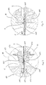
- the machining device shown in Figures 1 to 4 includes a frame 11 supporting a jaw 16 comprising two blades 161 and 162 mounted facing one another to delimit between said blades 161, 162 a calibration orifice 1.
- the device comprises means for forcing the sheet to move relative to the calibration orifice: a clamp 15 which can grip the sheet 2, clamp that can be moved relative to said blades 161 and 162. This involves closing the jaw 16 on sheet 2 while stretching said sheet 2.
- the clamp will not stray too far from a plane perpendicular to the plane of the orifice of calibration 1, passing through said orifice.
- the sheet is passed through a calibration orifice, creating a kind of die, if this is that it is not a question of spinning a wire, but of machining a sheet.
- the invention differs radically analogy to spinning by the shape of the orifice created, which creates a dimension new for addressing sheets.
- Said means for forcing the sheet to move relative to the calibration orifice are such that the spacing between the blades is continuously varied as a function of the movement of the clamp, so as to continuously vary the thickness of said sheet while it passes through the calibration hole.
- the law is such that the thickness evolves linearly according to the distance of distance. More precisely, the thickness decreases when the distance of distance increases.
- the invention also differs of the technical analogy of spinning by the variable nature of the calibration orifice.
- the machining device includes means for coordinate the movement of said clamp and the relative position of said blades so as to make slide the sheet relative to said blades while varying the distance between said blades blades according to a predetermined law according to the final shape to be obtained.
- this law can easily be adjusted experimentally according to the possible deviation between the form desired and the shape obtained during the first tests.
- the frame 11 is pierced in the center of a window 101 extended on one side by a clearance 102 (see FIG. 2), receiving said jaw 16.
- the blades are mounted one on 161 one fixed blade holder 13, the other 162 on a movable blade holder 14, by means of keys trapezoidal 131 and 141 respectively (see more particularly Figure 3).
- Back 130 of fixed blade holder 13 is a circular base cylinder, the axis of said cylinder being perpendicular to the plan of Figure 1.
- the purpose of this constructive arrangement is to be able to adjust the parallelism of the blades 161 and 162 by transversely moving the fixed blade holder 13 relative to the frame 11. Being given the range of adjustment sought, the radius of the arc of a circle formed by the face of this cylinder in the plane of Figure 1 is of radius so large that the curvature is not discernible at the figure 1.
- a corner 181 is interposed between the movable blade holder 14 and a reference surface 17 on the frame 11, with interposition of needle roller tracks 185.
- This corner 181 is mounted on a nut 183, itself mounted on a screw 180.
- the translation of the screw 180 along its axis is blocked by suitable arrangement.
- the translation of the movable blade holder 14 takes place while it remains always parallel to itself, the forces exerted by the mobile tool holder 14 in the direction parallel to the axis of the screw 180 are taken up by the frame 11.
- the movable blade holder 14 and all of the members cooperating therewith are held in place against the frame 11 by a plate 160.
- the corner 181 forms an angle ⁇ whose value is chosen to develop an effort on the sheet sufficient to deform it, while providing the possibility that the length of movement of the corner is sufficient to control with relative precision the relative movement of the blades.
- the opinion 180 is driven by a motor 186.
- the rotation of the screw 180 in one direction makes it possible to move the corner 181 in one direction (for example from left to right in Figure 1); shaft rotation 180 in the other direction makes it possible to move the corner 181 in the other direction.
- moving corner 181 from left to right in Figure 1 will increase the distance between the movable blade holder 14 and the reference surface 17, therefore decrease the distance between the movable blade holder 14 and the fixed blade holder 13, therefore reduce the distance between the blades 161 and 162.
- the looping of the forces involved passes through the frame 11, dimensioned accordingly.
- Return springs (not shown) ensure that the fixed blade 13 and movable blade 14 deviate from each other when the corner 181 is moved from right to left in FIG. 1.
- each of the blades 161 and 162 in the functional area, that is to say the area of the carried 165, has a rounded shape to define, with the blade opposite and taking into account the direction advancement of the sheet 2 through the jaw 16, converging spans forming a progressive necking.
- the profile of the blades 161 and 162 is here linear. More generally, if we find experimentally a deviation in this direction between the desired shape and the shape of the sheet after deformation, it is corrected by modifying the shape of said profile in order to obtain the shape of the sheet metal such that wish.
- Appropriate surface treatment makes it possible to impart hardness to said surface 165 suitable.
- tungsten carbide blades that have undergone a surface treatment based on titanium nitride and molybdenum disulphide, combined with lubrication, have a resistance and a sliding (coefficient of friction) suitable.
- Hoses 9 make it possible to spray a lubricant, for example machining oil, to cover the faces of the sheet just in front of the calibration hole.
- a lubricant for example machining oil
- a clamp 15, with a self-tightening jaw, is arranged in parallel with the jaw 16.
- This clamp includes clamps 151 of trapezoidal section interposed between the object to be clamped (here the sheet 2) and support surfaces 150 inclined so as to converge on the side of the jaw 16.
- the clamp 15 makes it possible to grip sheet 2 firmly by one of its ends.
- the clamp must of course be able to close to grip sheet 2 correctly and open to drop sheet 2.
- the necessary constructive details will be easily drawn by the skilled person and will not appear not on the drawing so as not to overload it unnecessarily.
- a traction mechanism (not shown) allows to move away (or to move closer to make the sheet reverse from two passes) the clamp 15 of the jaw 16, clamp and jaw remaining constantly parallel, the movement of the clamp intervening in a plane perpendicular to the plane in which the movement develops blades 161 and 162 of the jaw 16.
- a collet may be used hydraulic.
- the law is such that the thickness decreases when the distance increases.
- the movement of corner 181 and the distance of the clamp 15 are of course coordinated to obtain the desired profile on the sheet 2.
- the rate of deformation of the sheet does not exceed certain limits. It depends on the nature of the material. Also take into account the angle of bias and the length machined. In fact, taking into account the fact that the total volume of material is preserved, the parameter to take into account is the quantity of material displaced by machining. The more there are, the bigger will be the number of passes required. So, for example, for ductile stainless steel, if you want achieve a bias angle reaching the order of magnitude of 0.1 °, and for a machined length of around 10 centimeters, it is preferable to work in at least two successive passes. So, with each pass, a law is applied targeting different thicknesses. Work in several passes improves the level of precision and / or the surface finish.
- the invention allows machining without thermal input.
- the invention allows machining while having constant deformation rates throughout the worked section.
- the resulting benefit is the absence or at least the very low impact of parasitic deformations, hence no or very little warping of the sheet after machining.
- the proposed machining process fits easily into a more complex installation manufacturing drafts according to a particular application.
- a metal strip continuous whose width and thickness are chosen according to the width and thickness maximum of the blank bias to manufacture.
- the strip for example packaged in the form of coil, feeds a machining device as described. Even if the tape had a curvature initial due to its storage in a reel, the stretching due to the process automatically erases all curvature, which makes any subsequent straightening unnecessary.
- the tape reverses in the machining device between two passes.
- each pass can be performed on successive machining devices. During successive passes, the faces of the sheet remains flat, their relative inclination increasing.
- the strip is sectioned by closing jaw 16 further without longitudinal displacement of the strip relative to the clamp 15, to mark a sectioning area of said strip, and without release the tightening imposed by the blades 161 and 162, a blank is individualized by the traction on said strip by the clamp 15 until rupture.
- the deformation machining as proposed allows a great saving of material compared to material removal machining.
- the type of material depends on the intended application, the process suitable for all sufficiently ductile materials.
- the invention finds a particularly interesting application for machining steel sheets of thickness included between 0.5 millimeter and 3 millimeters.
- the invention advantageously applies to the manufacture of a type of tire tread mold. If we refer to the description of a mold for tire given in patent application EP 0 569 909, it can be seen that said mold is consisting of the stacking in the circumferential direction of a large number of elements, the section, seen in a plane perpendicular to the axis of the mold, is preferably trapezoidal.
- the invention provides a method which makes it possible to obtain a blank suitable for cutting said blanks. elements.
- Said elements are then cut to the desired profile so that, on the side of the most thin, part of the wafer is a molding zone of a corresponding wafer of the tread, and so that outside of said molding zone, the additional wafer in the part cited above cooperates with members controlling the opening movements and closing the mold.
- the steel thus machined is stainless steel, due to the use of the blanks in a mold for tire.
- blanks are mass produced by applying the process described above, then we chain the production by cutting, according to the desired profile, as and as one or more elements in each blank, and stacking as and when said elements to constitute said mold.
- the dimensions of the blank 3 More precisely, from the mathematical definition of the surface of the tread as the tire designer designed it, and from the choice of the number of elements that will include the crown ensuring the molding of said tread, the dimensions of the blank 3.
- the width L of the blank being sufficient to cut here a single element such as 31 by any suitable technique.
- a metal strip of departure is chosen according to the width L and the maximum thickness of the trapezoid.
- each of the elements 31 is then cut, preferably using means of section controlled by profile 32 of the tread to be molded.
- the cutting of the profile 32 will typically be different for each of the elements 31, depending on the shape of the sculpture of the tread to be molded.
- the invention lends itself perfectly well to manufacturing assisted by computer. From the computer files containing the definition of the sculpture, we can order a preform cutting tool, for example a laser cutting machine. The invention therefore allows the production of molds of the type described in the application for EP patent 0 569 909 according to a very direct method.
Landscapes
- Engineering & Computer Science (AREA)
- Mechanical Engineering (AREA)
- Moulds For Moulding Plastics Or The Like (AREA)
- Shaping Metal By Deep-Drawing, Or The Like (AREA)
- Tyre Moulding (AREA)
- Bending Of Plates, Rods, And Pipes (AREA)
Applications Claiming Priority (2)
| Application Number | Priority Date | Filing Date | Title |
|---|---|---|---|
| FR9714345 | 1997-11-13 | ||
| FR9714345A FR2770793A1 (fr) | 1997-11-13 | 1997-11-13 | Usinage de tole sans elevement de matiere, par etirage |
Publications (2)
| Publication Number | Publication Date |
|---|---|
| EP0916419A1 EP0916419A1 (fr) | 1999-05-19 |
| EP0916419B1 true EP0916419B1 (fr) | 2002-03-27 |
Family
ID=9513413
Family Applications (1)
| Application Number | Title | Priority Date | Filing Date |
|---|---|---|---|
| EP98120549A Expired - Lifetime EP0916419B1 (fr) | 1997-11-13 | 1998-10-30 | Usinage de tôle sans enlèvement de matière, par étirage |
Country Status (10)
| Country | Link |
|---|---|
| US (1) | US6044680A (enExample) |
| EP (1) | EP0916419B1 (enExample) |
| JP (1) | JPH11319976A (enExample) |
| KR (1) | KR100538897B1 (enExample) |
| CN (1) | CN1142041C (enExample) |
| BR (1) | BR9804603A (enExample) |
| CA (1) | CA2250991A1 (enExample) |
| CZ (1) | CZ368998A3 (enExample) |
| DE (1) | DE69804406T2 (enExample) |
| FR (1) | FR2770793A1 (enExample) |
Families Citing this family (6)
| Publication number | Priority date | Publication date | Assignee | Title |
|---|---|---|---|---|
| FR2832091A1 (fr) * | 2001-11-13 | 2003-05-16 | Michelin Soc Tech | Moule pour pneus |
| FR2839003A1 (fr) | 2002-04-29 | 2003-10-31 | Michelin Soc Tech | Moule pour pneus |
| CN100512993C (zh) * | 2007-12-29 | 2009-07-15 | 中国重型机械研究院 | 复合斜面夹紧系统 |
| CN100512992C (zh) * | 2007-12-29 | 2009-07-15 | 中国重型机械研究院 | 一种组合梁式张力拉伸方法 |
| CN102527908B (zh) * | 2011-12-09 | 2014-08-13 | 苏州工业园区高登威科技有限公司 | 机台 |
| CN104760219A (zh) * | 2015-04-10 | 2015-07-08 | 北京化工大学 | 可调制品厚度的实验模具 |
Family Cites Families (19)
| Publication number | Priority date | Publication date | Assignee | Title |
|---|---|---|---|---|
| US1217035A (en) * | 1916-03-13 | 1917-02-20 | Ernest L Mcdowell | Device for fitting eyeglass-lenses. |
| FR718044A (fr) * | 1931-06-02 | 1932-01-18 | Bleiindustrie Ag Vormals Jung | Presse à refoulement pour la fabrication des tôles |
| US2148469A (en) * | 1936-07-06 | 1939-02-28 | American Rolling Mill Co | Process and device for reducing sheet metal |
| US2224337A (en) * | 1937-03-30 | 1940-12-10 | Akron Standard Mold Co | Method of making tire molds |
| FR991116A (fr) * | 1949-07-22 | 1951-10-01 | Procédé et appareillage pour l'obtention de tôles et de bandes par allongement en matrice | |
| US2935114A (en) * | 1955-02-08 | 1960-05-03 | Anderson Frohman | Work gripping and drawing mechanism for sheet shaping machines operating on the forming-by-drawing principle |
| US3049035A (en) * | 1957-11-13 | 1962-08-14 | Ici Ltd | Apparatus for the reduction of metals or alloys |
| US3495427A (en) * | 1965-04-05 | 1970-02-17 | Cavitron Corp | Apparatus for altering the cross-sectional shape of a plastically deformable workpiece using high frequency vibrations |
| US3514989A (en) * | 1967-10-04 | 1970-06-02 | Foxboro Co | Method for die forming flexures using edge constraint |
| US3768296A (en) * | 1972-09-13 | 1973-10-30 | Wean United Inc | Method and apparatus for pressing and indenting a workpiece |
| US3921429A (en) * | 1974-04-11 | 1975-11-25 | Tadeusz Sendzimir | Process and apparatus for modifying the cross section of a slab |
| FR2515541B1 (enExample) * | 1981-10-30 | 1985-05-10 | Griset Ets | |
| JPS6027416A (ja) * | 1983-07-23 | 1985-02-12 | Kiyoshi Hajikano | ダイス前進装置 |
| JPS61182819A (ja) * | 1985-02-08 | 1986-08-15 | Hideo Kagami | 異形金属条の連続成形方法 |
| US5086635A (en) * | 1990-12-10 | 1992-02-11 | Chu Associates, Inc. | Method of and machine for forming compound curvatures in metal sheets by drawing |
| US5156036A (en) * | 1991-08-19 | 1992-10-20 | Ulrich Copper, Inc. | Method and apparatus for drawing open-sided channel members |
| JPH05293571A (ja) * | 1992-04-22 | 1993-11-09 | Ishikawajima Harima Heavy Ind Co Ltd | プレス製造装置 |
| DE69301059T2 (de) * | 1992-05-13 | 1996-05-15 | Sedepro | Reifenform und Verfahren zum Formen eines Reifens |
| KR101480164B1 (ko) * | 2011-11-25 | 2015-01-08 | 가톨릭대학교 산학협력단 | 쿠라리논 또는 고삼추출물을 포함하는 피부질환 예방 및 개선용 화장료 조성물 |
-
1997
- 1997-11-13 FR FR9714345A patent/FR2770793A1/fr active Pending
-
1998
- 1998-10-30 DE DE69804406T patent/DE69804406T2/de not_active Expired - Fee Related
- 1998-10-30 EP EP98120549A patent/EP0916419B1/fr not_active Expired - Lifetime
- 1998-11-10 US US09/189,450 patent/US6044680A/en not_active Expired - Fee Related
- 1998-11-10 BR BR9804603-9A patent/BR9804603A/pt not_active IP Right Cessation
- 1998-11-12 CA CA002250991A patent/CA2250991A1/fr not_active Abandoned
- 1998-11-13 CZ CZ983689A patent/CZ368998A3/cs unknown
- 1998-11-13 CN CNB981249094A patent/CN1142041C/zh not_active Expired - Fee Related
- 1998-11-13 JP JP10324278A patent/JPH11319976A/ja not_active Ceased
- 1998-11-13 KR KR1019980048520A patent/KR100538897B1/ko not_active Expired - Fee Related
Also Published As
| Publication number | Publication date |
|---|---|
| DE69804406T2 (de) | 2002-10-10 |
| DE69804406D1 (de) | 2002-05-02 |
| JPH11319976A (ja) | 1999-11-24 |
| CN1142041C (zh) | 2004-03-17 |
| US6044680A (en) | 2000-04-04 |
| CA2250991A1 (fr) | 1999-05-13 |
| EP0916419A1 (fr) | 1999-05-19 |
| KR100538897B1 (ko) | 2006-03-14 |
| FR2770793A1 (fr) | 1999-05-14 |
| CZ368998A3 (cs) | 1999-09-15 |
| BR9804603A (pt) | 1999-11-16 |
| KR19990045255A (ko) | 1999-06-25 |
| CN1223178A (zh) | 1999-07-21 |
Similar Documents
| Publication | Publication Date | Title |
|---|---|---|
| EP3181312A1 (fr) | Agencement réglable de transformation d'un support plan, cassette, unité, et machine ainsi équipée | |
| EP3492249A1 (fr) | Procédé et installation de bobinage d'une bande de tissu pré-imprégnée sur une surface inclinée | |
| FR2898600A1 (fr) | Appareil et procede pour detacher des troncons de barreaux de verre, troncon de barreaux de verre ainsi produit et guide d'onde optique comprenant un tel troncon | |
| EP0916419B1 (fr) | Usinage de tôle sans enlèvement de matière, par étirage | |
| FR2565520A1 (fr) | Dispositif de coupe automatique des tubes en carton et autres | |
| FR3001903A1 (fr) | Installation et procede de laminage | |
| EP0916421B1 (fr) | Usinage d'une tôle sans enlévement de matiére, par écrasement | |
| EP1903975A1 (fr) | Ebauche pour la fabrication d'un instrument endodontique et procede pour la fabrication dudit instrument | |
| CH691036A5 (fr) | Dispositif de sciage par fil pour la découpe de tranches fines comprenant un mécanisme pour le taillage in situ des gorges des cylindres guide-fils. | |
| FR2716394A1 (fr) | Procédé et dispositif pour couper des corps creux. | |
| EP0177418A1 (fr) | Dispositif de tronçonnage d'un tube carton à surface dure | |
| EP3490747B1 (fr) | Couteau rotatif pour machine de production d'emballages et procede utilisant ledit couteau | |
| EP3010675B1 (fr) | Ensemble de plaques obtenues par decoupe d'un bloc en materiau metallique ou composite | |
| FR2600919A1 (fr) | Procede et dispositif pour la retouche due a l'usure des cylindres d'un laminoir, sur la ligne de laminage | |
| EP2598284B1 (fr) | Dispositif pour l'introduction, le guidage et l'evacuation de pieces cylindriques, telles que des pastilles de combustible nucleaire, dans une rectifieuse sans centre | |
| EP1670621B1 (fr) | Procede de coupe d'un tube en ligne et dispositif de coupe mettant en oeuvre ledit procede | |
| EP3255510B1 (fr) | Calandre et procede de calandrage de ressort de barillet d'horlogerie | |
| FR2937576A1 (fr) | Procede et dispositif de realisation de pieces de revolution notamment en bois | |
| EP1771587A2 (fr) | Procédé de réalisation d'un arbre de lanceur de démarreur | |
| CH702859B1 (fr) | Dispositif et procédé de décolletage-fraisage. | |
| EP0100743A1 (fr) | Procédé de laminage à froid de tubes au moyen d'un laminoir à pas de pélerin et dispositif pour la mise en oeuvre du procédé | |
| BE626624A (enExample) | ||
| BE474686A (enExample) | ||
| FR2489722A1 (fr) | Procede de fabrication d'aubes et dispositif pour leur vrillage | |
| BE536306A (enExample) |
Legal Events
| Date | Code | Title | Description |
|---|---|---|---|
| PUAI | Public reference made under article 153(3) epc to a published international application that has entered the european phase |
Free format text: ORIGINAL CODE: 0009012 |
|
| AK | Designated contracting states |
Kind code of ref document: A1 Designated state(s): BE CH DE FR GB IT LI |
|
| AX | Request for extension of the european patent |
Free format text: AL;LT;LV;MK;RO;SI |
|
| 17P | Request for examination filed |
Effective date: 19991119 |
|
| AKX | Designation fees paid |
Free format text: BE CH DE FR GB IT LI |
|
| GRAG | Despatch of communication of intention to grant |
Free format text: ORIGINAL CODE: EPIDOS AGRA |
|
| 17Q | First examination report despatched |
Effective date: 20010530 |
|
| GRAG | Despatch of communication of intention to grant |
Free format text: ORIGINAL CODE: EPIDOS AGRA |
|
| GRAH | Despatch of communication of intention to grant a patent |
Free format text: ORIGINAL CODE: EPIDOS IGRA |
|
| REG | Reference to a national code |
Ref country code: GB Ref legal event code: IF02 |
|
| GRAH | Despatch of communication of intention to grant a patent |
Free format text: ORIGINAL CODE: EPIDOS IGRA |
|
| GRAA | (expected) grant |
Free format text: ORIGINAL CODE: 0009210 |
|
| RIN1 | Information on inventor provided before grant (corrected) |
Inventor name: PEGORARO, GIANCARLO |
|
| AK | Designated contracting states |
Kind code of ref document: B1 Designated state(s): BE CH DE FR GB IT LI |
|
| REG | Reference to a national code |
Ref country code: CH Ref legal event code: EP |
|
| REF | Corresponds to: |
Ref document number: 69804406 Country of ref document: DE Date of ref document: 20020502 |
|
| GBT | Gb: translation of ep patent filed (gb section 77(6)(a)/1977) |
Effective date: 20020626 |
|
| PLBE | No opposition filed within time limit |
Free format text: ORIGINAL CODE: 0009261 |
|
| STAA | Information on the status of an ep patent application or granted ep patent |
Free format text: STATUS: NO OPPOSITION FILED WITHIN TIME LIMIT |
|
| 26N | No opposition filed |
Effective date: 20021230 |
|
| PGFP | Annual fee paid to national office [announced via postgrant information from national office to epo] |
Ref country code: CH Payment date: 20061012 Year of fee payment: 9 |
|
| PGFP | Annual fee paid to national office [announced via postgrant information from national office to epo] |
Ref country code: GB Payment date: 20061023 Year of fee payment: 9 |
|
| PGFP | Annual fee paid to national office [announced via postgrant information from national office to epo] |
Ref country code: IT Payment date: 20061031 Year of fee payment: 9 |
|
| PGFP | Annual fee paid to national office [announced via postgrant information from national office to epo] |
Ref country code: BE Payment date: 20061123 Year of fee payment: 9 |
|
| REG | Reference to a national code |
Ref country code: FR Ref legal event code: TP |
|
| BERE | Be: lapsed |
Owner name: CONCEPTION ET DEVELOPPEMENT *MICHELIN Effective date: 20071031 |
|
| GBPC | Gb: european patent ceased through non-payment of renewal fee |
Effective date: 20071030 |
|
| REG | Reference to a national code |
Ref country code: CH Ref legal event code: PL |
|
| PG25 | Lapsed in a contracting state [announced via postgrant information from national office to epo] |
Ref country code: CH Free format text: LAPSE BECAUSE OF NON-PAYMENT OF DUE FEES Effective date: 20071031 Ref country code: LI Free format text: LAPSE BECAUSE OF NON-PAYMENT OF DUE FEES Effective date: 20071031 |
|
| PG25 | Lapsed in a contracting state [announced via postgrant information from national office to epo] |
Ref country code: BE Free format text: LAPSE BECAUSE OF NON-PAYMENT OF DUE FEES Effective date: 20071031 |
|
| PG25 | Lapsed in a contracting state [announced via postgrant information from national office to epo] |
Ref country code: GB Free format text: LAPSE BECAUSE OF NON-PAYMENT OF DUE FEES Effective date: 20071030 |
|
| PGFP | Annual fee paid to national office [announced via postgrant information from national office to epo] |
Ref country code: DE Payment date: 20081022 Year of fee payment: 11 |
|
| PGFP | Annual fee paid to national office [announced via postgrant information from national office to epo] |
Ref country code: FR Payment date: 20081014 Year of fee payment: 11 |
|
| PG25 | Lapsed in a contracting state [announced via postgrant information from national office to epo] |
Ref country code: IT Free format text: LAPSE BECAUSE OF NON-PAYMENT OF DUE FEES Effective date: 20071030 |
|
| REG | Reference to a national code |
Ref country code: FR Ref legal event code: ST Effective date: 20100630 |
|
| PG25 | Lapsed in a contracting state [announced via postgrant information from national office to epo] |
Ref country code: FR Free format text: LAPSE BECAUSE OF NON-PAYMENT OF DUE FEES Effective date: 20091102 Ref country code: DE Free format text: LAPSE BECAUSE OF NON-PAYMENT OF DUE FEES Effective date: 20100501 |