EP0915557B1 - Wechselstromgenerator für kraftfahrzeuge - Google Patents
Wechselstromgenerator für kraftfahrzeuge Download PDFInfo
- Publication number
- EP0915557B1 EP0915557B1 EP97944186A EP97944186A EP0915557B1 EP 0915557 B1 EP0915557 B1 EP 0915557B1 EP 97944186 A EP97944186 A EP 97944186A EP 97944186 A EP97944186 A EP 97944186A EP 0915557 B1 EP0915557 B1 EP 0915557B1
- Authority
- EP
- European Patent Office
- Prior art keywords
- coil
- end portions
- alternator
- spaces
- disposed
- Prior art date
- Legal status (The legal status is an assumption and is not a legal conclusion. Google has not performed a legal analysis and makes no representation as to the accuracy of the status listed.)
- Revoked
Links
- 238000001816 cooling Methods 0.000 claims abstract description 115
- 238000004804 winding Methods 0.000 claims description 54
- 230000017525 heat dissipation Effects 0.000 claims description 23
- 239000000853 adhesive Substances 0.000 claims description 10
- 230000001070 adhesive effect Effects 0.000 claims description 10
- 230000004888 barrier function Effects 0.000 claims description 8
- 230000004907 flux Effects 0.000 claims description 4
- 238000009423 ventilation Methods 0.000 abstract description 2
- 230000002093 peripheral effect Effects 0.000 abstract 1
- 239000010410 layer Substances 0.000 description 33
- 210000000078 claw Anatomy 0.000 description 15
- 239000002826 coolant Substances 0.000 description 10
- 230000000694 effects Effects 0.000 description 9
- 230000007423 decrease Effects 0.000 description 5
- XLYOFNOQVPJJNP-UHFFFAOYSA-N water Substances O XLYOFNOQVPJJNP-UHFFFAOYSA-N 0.000 description 4
- 240000000543 Pentas lanceolata Species 0.000 description 2
- 238000005299 abrasion Methods 0.000 description 2
- 239000000463 material Substances 0.000 description 2
- RYGMFSIKBFXOCR-UHFFFAOYSA-N Copper Chemical compound [Cu] RYGMFSIKBFXOCR-UHFFFAOYSA-N 0.000 description 1
- 229910000576 Laminated steel Inorganic materials 0.000 description 1
- 238000010521 absorption reaction Methods 0.000 description 1
- 230000004323 axial length Effects 0.000 description 1
- 230000005540 biological transmission Effects 0.000 description 1
- 230000008859 change Effects 0.000 description 1
- 239000011248 coating agent Substances 0.000 description 1
- 238000000576 coating method Methods 0.000 description 1
- 230000008602 contraction Effects 0.000 description 1
- 239000011810 insulating material Substances 0.000 description 1
- 238000004519 manufacturing process Methods 0.000 description 1
- 239000012260 resinous material Substances 0.000 description 1
- 239000002356 single layer Substances 0.000 description 1
- 238000011144 upstream manufacturing Methods 0.000 description 1
Images


Classifications
-
- H—ELECTRICITY
- H02—GENERATION; CONVERSION OR DISTRIBUTION OF ELECTRIC POWER
- H02K—DYNAMO-ELECTRIC MACHINES
- H02K3/00—Details of windings
- H02K3/32—Windings characterised by the shape, form or construction of the insulation
- H02K3/34—Windings characterised by the shape, form or construction of the insulation between conductors or between conductor and core, e.g. slot insulation
-
- H—ELECTRICITY
- H02—GENERATION; CONVERSION OR DISTRIBUTION OF ELECTRIC POWER
- H02K—DYNAMO-ELECTRIC MACHINES
- H02K9/00—Arrangements for cooling or ventilating
- H02K9/22—Arrangements for cooling or ventilating by solid heat conducting material embedded in, or arranged in contact with, the stator or rotor, e.g. heat bridges
- H02K9/227—Heat sinks
-
- H—ELECTRICITY
- H02—GENERATION; CONVERSION OR DISTRIBUTION OF ELECTRIC POWER
- H02K—DYNAMO-ELECTRIC MACHINES
- H02K3/00—Details of windings
- H02K3/04—Windings characterised by the conductor shape, form or construction, e.g. with bar conductors
- H02K3/12—Windings characterised by the conductor shape, form or construction, e.g. with bar conductors arranged in slots
-
- H—ELECTRICITY
- H02—GENERATION; CONVERSION OR DISTRIBUTION OF ELECTRIC POWER
- H02K—DYNAMO-ELECTRIC MACHINES
- H02K3/00—Details of windings
- H02K3/04—Windings characterised by the conductor shape, form or construction, e.g. with bar conductors
- H02K3/24—Windings characterised by the conductor shape, form or construction, e.g. with bar conductors with channels or ducts for cooling medium between the conductors
-
- H—ELECTRICITY
- H02—GENERATION; CONVERSION OR DISTRIBUTION OF ELECTRIC POWER
- H02K—DYNAMO-ELECTRIC MACHINES
- H02K9/00—Arrangements for cooling or ventilating
- H02K9/02—Arrangements for cooling or ventilating by ambient air flowing through the machine
- H02K9/04—Arrangements for cooling or ventilating by ambient air flowing through the machine having means for generating a flow of cooling medium
- H02K9/06—Arrangements for cooling or ventilating by ambient air flowing through the machine having means for generating a flow of cooling medium with fans or impellers driven by the machine shaft
-
- H—ELECTRICITY
- H02—GENERATION; CONVERSION OR DISTRIBUTION OF ELECTRIC POWER
- H02K—DYNAMO-ELECTRIC MACHINES
- H02K1/00—Details of the magnetic circuit
- H02K1/06—Details of the magnetic circuit characterised by the shape, form or construction
- H02K1/22—Rotating parts of the magnetic circuit
- H02K1/32—Rotating parts of the magnetic circuit with channels or ducts for flow of cooling medium
- H02K1/325—Rotating parts of the magnetic circuit with channels or ducts for flow of cooling medium between salient poles
-
- H—ELECTRICITY
- H02—GENERATION; CONVERSION OR DISTRIBUTION OF ELECTRIC POWER
- H02K—DYNAMO-ELECTRIC MACHINES
- H02K3/00—Details of windings
- H02K3/46—Fastening of windings on the stator or rotor structure
- H02K3/50—Fastening of winding heads, equalising connectors, or connections thereto
Definitions
- the coil-end portions are in contact with the frame to increase the resistance of draft and cooling medium passing through the inside of the coil-end portions, so that heat of the coil ends can be transmitted to the frame, thereby lowering the temperature of the coil-end portions.
- FIG. 9 is a cross-sectional fragmental view illustrating a portion according to another embodiment of the present invention
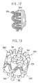
- Fig. 10 is a plan view illustrating the coil-end portion according to another embodiment of the present invention
- Fig. 11 is a cross-sectional view of the coil-end portion illustrated in Fig. 10
- Fig. 12 is a plan view of the coil-end portion illustrated in Fig. 10
- Fig. 13 is a perspective view illustrating a rotor according to another embodiment of the present invention
- Fig. 14 is a cross-sectional view of an alternator according to another embodiment of the present invention
- Fig. 15 is a cross-sectional view illustrating a magnet wire according to another embodiment of the present invention.
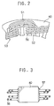
- the single-layer wave-wound coils shown in Fig. 2 can be changed to double-layer wave-wound coils.
- the double-layer wave-wound coils provide not only the coil ends of each of the phase-winding but also the coil ends of two-layered clusters of the coil ends, thereby providing many spaces in the coil-end portions by comparatively simple manufacturing process.
- Such double-wound coils are disclosed in JP-B2-3-73225 and in Figs. 10, 11 and 12, where double-layer 2 ⁇ /3-short-pitch wave-wound coils are disclosed.
- the coil ends thereof extend from the same slot to opposite directions. Therefore, the spaces between the coil ends can be provided easily.
Landscapes
- Engineering & Computer Science (AREA)
- Power Engineering (AREA)
- Motor Or Generator Cooling System (AREA)
Claims (20)
- Generator (1) für ein Fahrzeug, mit einem an einem Gehäuse (10) befestigten Statorkern (40), auf dem eine Drehstrom-Ankerwicklung (50) mit Spulenendabschnitten (54, 55) ausgebildet ist, die aus einer Mehrzahl von Spulenenden (56) bestehen, einem Läufer (30), der dem Statorkern (40) gegenüberliegend angeordnet ist, und von dem Läufer angetriebenen Einrichtungen (33, 34) zum Erzeugen von Kühlungsluft, die in dem Gehäuse (10) strömt, wobei
die Spulenenden (56) der Spulenendabschnitte (54, 55) voneinander beabstandet sind, so daß sie in einem Abschnitt eine Büschelform bilden und dadurch eine Mehrzahl von Zwischenräumen bilden, so daß die Kühlungsluft durch die Zwischenräume hindurchtritt. - Generator nach Anspruch 1, wobei
die Spulenenden (56) der Spulenendabschnitte (54, 55) voneinander so beabstandet sind, daß die Zwischenräume in jeder der Drehstromwicklungen vorhanden sind, wobei die Spulenenden (56) in zwei Lagen von einer der Phasenwicklungen aufgeteilt sind, so daß sie sich von Basisabschnitten davon in einem Winkel zueinander erstrecken, wodurch Zwischenräume zwischen den Basisabschnitten ausgebildet werden. - Generator nach Anspruch 1 oder 2, wobei
die Größe der Zwischenräume in den Spulenendabschnitten jeweils zwischen ca. 1/10 und einem ganzen Durchmesser eines Drahtes der Ankerwicklung (50) beträgt. - Generator nach Anspruch 1, wobei
eine Mehrzahl der Spulenenden (56), die sich aus einem der Schlitze des Statorkerns (40) erstrecken, mit einem Imprägnierkleber nur an den Basisabschnitten verklebt sind, um die Zwischenräume zu verschließen. - Generator nach Anspruch 1, wobei
die Spulenendabschnitte (54, 55) unterschiedlich große Zwischenräume aufweisen, und Zwischenräume entlang von Luftstrompassagen größer als andere Zwischenräume sind. - Generator nach Anspruch 5, wobei
die größeren Zwischenräume an axialen Enden der Spulenendabschnitte (54, 55) angeordnet sind. - Generator nach einem der Ansprüche 1 - 6, der des weiteren einen mit dem Läufer (30) drehbaren Ventilator (33) auf einer radialen Innenseite der Spulenendabschnitte (54, 55) aufweist, einzelne Enden der Spulenendabschnitte radial im Inneren des Innenumfangs des Statorkerns angeordnet sind, und die Spulenendabschnitte so verjüngt sind, daß sie den Ventilator überdecken.
- Generator nach einem der Ansprüche 1 - 3, wobei
die Spulenendabschnitte (54, 55) in der Nähe des Gehäuses (10) in einem Abstand angeordnet sind, der annähernd gleich einer Größe der Zwischenräume ist. - Generator nach einem der Ansprüche 1 - 3, wobei
die Spulenendabschnitte (54, 55) in Anlagekontakt mit dem Gehäuse (10) stehen, so daß Wärme von den Spulenenden (56) auf das Gehäuse (10) übertragen werden kann. - Generator nach Anspruch 8 oder 9, der des weiteren ein flexibles, wärmeleitendes Dämmelement (10a) aufweist, das in der Nähe oder in Berührung mit den Spulenendabschnitten (54, 55) angeordnet ist.
- Generator nach Anspruch 1 oder 4, der des weiteren aufweist:Dämmfolien (41), die zwischen der Ankerwicklung (50) und dem Statorkern (40) angeordnet sind, um sie voneinander zu isolieren, wobeiein axiales Ende der Folien sich von einem axialen Ende des Statorkerns erstreckt, so daß es Zwischenräume zwischen den Spulenenden und dem Statorkern an den Basisabschnitten verschließt und dadurch einen solchen Luftstromwiderstand zur Verfügung stellt, daß eine größere Menge der Kühlluft in die Zwischenräume in den Spulenendabschnitten als in die Zwischenräume zwischen den Spulenendabschnitten und dem Statorkern eingeleitet werden kann.
- Generator nach Anspruch 1 oder 7, der des weiteren einen zentrifugalen Ventilator (34) aufweist, der mit dem radial in den Spulenendabschnitten (54, 55) in deren Nähe angeordneten Läufer drehbar ist, wodurch die Spulenendabschnitte in einem Bereich angeordnet sind, in dem die durch den Ventilator angetriebene Windkraft am stärksten ist.
- Generator nach Anspruch 12, wobei
der Läufer (30) einen Polkern vom Lundell-Typ, den Ventilator und ein Blockierelement (370) zum Verschließen der U-förmigen Öffnungen eines Scheibenabschnitts des Polkerns aufweist, so daß Wandoberflächen der U-förmigen Öffnung als Ventilator ausgebildet sind. - Generator nach Anspruch 13, wobei
das Blockierelement (370) so angeordnet ist, daß es einem Ende des Statorkerns entspricht. - Generator nach Anspruch 13, wobei
das Blockierelement (370) ein zwischen Polen des Polkerns angeordnetes, nichtmagnetisches Element ist, wobei ein Permanentmagnet (35) die Polarität zum Unterdrücken eines Leckflusses zwischen den Polen besitzt, oder ein Magnethalter. - Generator nach einem der Ansprüche 1 - 11, wobei
die Kühlluft von radial außen von den Spulenendabschnitten (54, 55) eingeleitet wird. - Generator für ein Fahrzeug nach Anspruch 1, wobei
jeder der Spulenendabschnitte (54, 55) der Ankerwicklung (50) durch das Teilen von Drähten gebildet ist, die sich aus dem gleichen Schlitz in zwei Gruppen jeweils in entgegengesetzte Umfangsrichtungen erstrecken. - Generator nach Anspruch 17, wobei
die Ankerwicklung (50) doppellagige, wellig gewickelte Wicklungen aufweist. - Generator nach Anspruch 17, wobei
die Ankerwicklung (50) doppellagige Wicklungen mit einer kurzen 2π/3-Steigung aufweist. - Generator nach einem der Ansprüche 17 - 19, wobei
die Lagen der doppellagigen Wicklungen jeweils voneinander verschoben sind, um den Luftstromwiderstand zwischen den Lagen zu verringern, wodurch die Wärmeableitung verstärkt wird.
Priority Applications (1)
| Application Number | Priority Date | Filing Date | Title |
|---|---|---|---|
| EP99118718A EP0989657B1 (de) | 1997-03-10 | 1997-10-20 | Wechselstromgenerator für Kraftfahrzeuge |
Applications Claiming Priority (6)
| Application Number | Priority Date | Filing Date | Title |
|---|---|---|---|
| JP5498897 | 1997-03-10 | ||
| JP5498897 | 1997-03-10 | ||
| PCT/JP1997/001840 WO1998040953A1 (en) | 1997-03-10 | 1997-05-28 | Ac generator for vehicle |
| WOPCT/JP18/04097 | 1997-05-28 | ||
| WOPCT/JP97/01840 | 1997-05-28 | ||
| PCT/JP1997/003789 WO1998040956A1 (en) | 1997-03-10 | 1997-10-20 | Ac generator for vehicle |
Related Child Applications (1)
| Application Number | Title | Priority Date | Filing Date |
|---|---|---|---|
| EP99118718A Division EP0989657B1 (de) | 1997-03-10 | 1997-10-20 | Wechselstromgenerator für Kraftfahrzeuge |
Publications (3)
| Publication Number | Publication Date |
|---|---|
| EP0915557A4 EP0915557A4 (de) | 1999-05-12 |
| EP0915557A1 EP0915557A1 (de) | 1999-05-12 |
| EP0915557B1 true EP0915557B1 (de) | 2001-05-09 |
Family
ID=12986042
Family Applications (2)
| Application Number | Title | Priority Date | Filing Date |
|---|---|---|---|
| EP99118718A Expired - Lifetime EP0989657B1 (de) | 1997-03-10 | 1997-10-20 | Wechselstromgenerator für Kraftfahrzeuge |
| EP97944186A Revoked EP0915557B1 (de) | 1997-03-10 | 1997-10-20 | Wechselstromgenerator für kraftfahrzeuge |
Family Applications Before (1)
| Application Number | Title | Priority Date | Filing Date |
|---|---|---|---|
| EP99118718A Expired - Lifetime EP0989657B1 (de) | 1997-03-10 | 1997-10-20 | Wechselstromgenerator für Kraftfahrzeuge |
Country Status (3)
| Country | Link |
|---|---|
| EP (2) | EP0989657B1 (de) |
| DE (1) | DE69732578T2 (de) |
| WO (2) | WO1998040953A1 (de) |
Families Citing this family (14)
| Publication number | Priority date | Publication date | Assignee | Title |
|---|---|---|---|---|
| JP3250533B2 (ja) | 1998-11-25 | 2002-01-28 | 株式会社デンソー | 車両用交流発電機の固定子及びその製造方法 |
| JP3956075B2 (ja) * | 1999-04-12 | 2007-08-08 | 株式会社デンソー | 車両用交流発電機 |
| JP4318827B2 (ja) * | 2000-02-24 | 2009-08-26 | 三菱電機株式会社 | 交流発電機 |
| JP3650303B2 (ja) * | 2000-02-29 | 2005-05-18 | 三菱電機株式会社 | 交流発電機 |
| JP3786059B2 (ja) | 2002-06-25 | 2006-06-14 | 株式会社デンソー | 回転電機のセグメント順次接合ステータコイルおよびその製造方法 |
| JP3832392B2 (ja) | 2002-06-25 | 2006-10-11 | 株式会社デンソー | 回転電機のセグメント順次接合ステータコイルおよびその製造方法 |
| CA2531634A1 (en) * | 2003-07-10 | 2005-01-27 | Magnetic Applications Inc. | Compact high power alternator |
| DE102008022105B4 (de) * | 2008-04-09 | 2023-11-09 | Liebherr-Electronics and Drives GmbH | Flüssigkeitsgekühlte elektrische Maschine sowie Verfahren zur Kühlung einer solchen elektrischen Maschine |
| FR2993419B1 (fr) * | 2012-07-11 | 2016-01-01 | Valeo Equip Electr Moteur | Machine electrique tournante pour vehicule automobile |
| FR2993421B1 (fr) * | 2012-07-11 | 2015-08-07 | Valeo Equip Electr Moteur | Machine electrique tournante pour vehicule automobile |
| FR2993420B1 (fr) * | 2012-07-11 | 2016-01-01 | Valeo Equip Electr Moteur | Machine electrique tournante pour vehicule automobile |
| FR3020212B1 (fr) * | 2014-04-17 | 2017-11-03 | Valeo Equip Electr Moteur | Machine electrique tournante a refroidissement optimise |
| JP5989181B2 (ja) * | 2015-04-28 | 2016-09-07 | 三菱電機株式会社 | 回転電機 |
| EP4350958A4 (de) | 2021-06-02 | 2025-04-02 | Nissan Motor Co., Ltd. | Elektrische drehmaschine |
Family Cites Families (7)
| Publication number | Priority date | Publication date | Assignee | Title |
|---|---|---|---|---|
| JPS55147941A (en) * | 1979-05-07 | 1980-11-18 | Mitsubishi Electric Corp | Ventilation cooling system for rotary electric machine |
| JPS58166271U (ja) * | 1982-04-28 | 1983-11-05 | 株式会社デンソー | 車両用交流発電機 |
| JPS59111482U (ja) * | 1983-01-17 | 1984-07-27 | 株式会社東芝 | 直流機 |
| JPS59159638A (ja) * | 1983-03-01 | 1984-09-10 | Nippon Denso Co Ltd | 車両用交流発電機 |
| JPS6359744A (ja) * | 1986-08-28 | 1988-03-15 | Mitsuba Electric Mfg Co Ltd | 車両用発電機のステ−タコイル構造 |
| US4908541A (en) * | 1986-08-28 | 1990-03-13 | Mitsuba Electric Mfg., Co., Ltd. | Air-cooled layered coil vehicle AC generator stator |
| JPH01123452U (de) * | 1988-02-18 | 1989-08-22 |
-
1997
- 1997-05-28 WO PCT/JP1997/001840 patent/WO1998040953A1/ja not_active Ceased
- 1997-10-20 DE DE69732578T patent/DE69732578T2/de not_active Expired - Lifetime
- 1997-10-20 EP EP99118718A patent/EP0989657B1/de not_active Expired - Lifetime
- 1997-10-20 EP EP97944186A patent/EP0915557B1/de not_active Revoked
- 1997-10-20 WO PCT/JP1997/003789 patent/WO1998040956A1/ja not_active Ceased
Also Published As
| Publication number | Publication date |
|---|---|
| EP0915557A4 (de) | 1999-05-12 |
| DE69732578T2 (de) | 2005-12-29 |
| WO1998040956A1 (en) | 1998-09-17 |
| EP0915557A1 (de) | 1999-05-12 |
| EP0989657A3 (de) | 2000-04-19 |
| EP0989657A2 (de) | 2000-03-29 |
| WO1998040953A1 (en) | 1998-09-17 |
| EP0989657B1 (de) | 2005-02-23 |
| DE69732578D1 (de) | 2005-03-31 |
Similar Documents
| Publication | Publication Date | Title |
|---|---|---|
| US5955804A (en) | Alternator winding arrangement with coil ends spaced apart from one another for air passage | |
| EP0915557B1 (de) | Wechselstromgenerator für kraftfahrzeuge | |
| US5965965A (en) | Stator winding arrangement of alternator for vehicle | |
| US6486586B2 (en) | Alternator | |
| KR101096469B1 (ko) | 소형 고전력 교류 발전기 | |
| EP0967709B1 (de) | Stator eines Wechselstromgenerators für Fahrzeuge und dessen Herstellungsverfahren | |
| JP3456140B2 (ja) | 車両用交流発電機 | |
| JP3438581B2 (ja) | 車両用交流発電機 | |
| JP3347118B2 (ja) | 交流発電機 | |
| US6946759B2 (en) | Stator for an automotive alternator and method of manufacturing the same | |
| EP1124305B1 (de) | Städerwickelkopf für eine Drehstromlichtmaschine eines Fahrzeuges | |
| EP0977342B1 (de) | Wechselstromgenerator mit Klauenpolrotor | |
| US6528910B2 (en) | Cooling arrangement of vehicle rotary electric machine | |
| US20100090561A1 (en) | Projecting pole rotor comprising coil end support plates and rotary electric machine comprising one such rotor | |
| KR100411458B1 (ko) | 교류발전기 | |
| EP1777798B1 (de) | Elektrische drehmaschine | |
| KR20030020368A (ko) | 회전 전기 기계 | |
| KR20020037732A (ko) | 차량용 교류 발전기 | |
| JPS59159638A (ja) | 車両用交流発電機 | |
| MXPA06002518A (es) | Maquina electrica giratoria polifasica, tal como un alternador o un alternador-motor de arranque, particularmente para un vehiculo automovil. | |
| EP1465321B1 (de) | Wicklungsanordnung eines Ständers eines Wechselstromgenerators für Fahrzeuge | |
| JP3780528B2 (ja) | 車両用交流発電機 | |
| JPH0127406Y2 (de) | ||
| EP0881753B1 (de) | Anordnung zum Kühlen von Wechselstromgeneratoren | |
| EP1109294B1 (de) | Wechselstromgenerator |
Legal Events
| Date | Code | Title | Description |
|---|---|---|---|
| PUAI | Public reference made under article 153(3) epc to a published international application that has entered the european phase |
Free format text: ORIGINAL CODE: 0009012 |
|
| 17P | Request for examination filed |
Effective date: 19980722 |
|
| A4 | Supplementary search report drawn up and despatched |
Effective date: 19990202 |
|
| AK | Designated contracting states |
Kind code of ref document: A4 Designated state(s): DE FR GB IT Kind code of ref document: A1 Designated state(s): DE FR GB IT |
|
| GRAG | Despatch of communication of intention to grant |
Free format text: ORIGINAL CODE: EPIDOS AGRA |
|
| 17Q | First examination report despatched |
Effective date: 19990723 |
|
| GRAG | Despatch of communication of intention to grant |
Free format text: ORIGINAL CODE: EPIDOS AGRA |
|
| GRAH | Despatch of communication of intention to grant a patent |
Free format text: ORIGINAL CODE: EPIDOS IGRA |
|
| GRAH | Despatch of communication of intention to grant a patent |
Free format text: ORIGINAL CODE: EPIDOS IGRA |
|
| GRAA | (expected) grant |
Free format text: ORIGINAL CODE: 0009210 |
|
| AK | Designated contracting states |
Kind code of ref document: B1 Designated state(s): DE FR GB IT |
|
| ITF | It: translation for a ep patent filed | ||
| REF | Corresponds to: |
Ref document number: 69704773 Country of ref document: DE Date of ref document: 20010613 |
|
| ET | Fr: translation filed | ||
| REG | Reference to a national code |
Ref country code: GB Ref legal event code: IF02 |
|
| PLBQ | Unpublished change to opponent data |
Free format text: ORIGINAL CODE: EPIDOS OPPO |
|
| PLBI | Opposition filed |
Free format text: ORIGINAL CODE: 0009260 |
|
| PLBF | Reply of patent proprietor to notice(s) of opposition |
Free format text: ORIGINAL CODE: EPIDOS OBSO |
|
| 26 | Opposition filed |
Opponent name: VONDROVSKY, GABRIEL Effective date: 20020208 |
|
| PLBF | Reply of patent proprietor to notice(s) of opposition |
Free format text: ORIGINAL CODE: EPIDOS OBSO |
|
| APBM | Appeal reference recorded |
Free format text: ORIGINAL CODE: EPIDOSNREFNO |
|
| APBP | Date of receipt of notice of appeal recorded |
Free format text: ORIGINAL CODE: EPIDOSNNOA2O |
|
| APAH | Appeal reference modified |
Free format text: ORIGINAL CODE: EPIDOSCREFNO |
|
| APBQ | Date of receipt of statement of grounds of appeal recorded |
Free format text: ORIGINAL CODE: EPIDOSNNOA3O |
|
| PGFP | Annual fee paid to national office [announced via postgrant information from national office to epo] |
Ref country code: DE Payment date: 20101013 Year of fee payment: 14 |
|
| PGFP | Annual fee paid to national office [announced via postgrant information from national office to epo] |
Ref country code: GB Payment date: 20101020 Year of fee payment: 14 Ref country code: IT Payment date: 20101021 Year of fee payment: 14 |
|
| PGFP | Annual fee paid to national office [announced via postgrant information from national office to epo] |
Ref country code: FR Payment date: 20111103 Year of fee payment: 15 |
|
| REG | Reference to a national code |
Ref country code: DE Ref legal event code: R103 Ref document number: 69704773 Country of ref document: DE Ref country code: DE Ref legal event code: R064 Ref document number: 69704773 Country of ref document: DE |
|
| APBU | Appeal procedure closed |
Free format text: ORIGINAL CODE: EPIDOSNNOA9O |
|
| APBW | Interlocutory revision of appeal recorded |
Free format text: ORIGINAL CODE: EPIDOSNIRAPO |
|
| RDAF | Communication despatched that patent is revoked |
Free format text: ORIGINAL CODE: EPIDOSNREV1 |
|
| RDAG | Patent revoked |
Free format text: ORIGINAL CODE: 0009271 |
|
| STAA | Information on the status of an ep patent application or granted ep patent |
Free format text: STATUS: PATENT REVOKED |
|
| 27W | Patent revoked |
Effective date: 20120412 |
|
| GBPR | Gb: patent revoked under art. 102 of the ep convention designating the uk as contracting state |
Effective date: 20120412 |
|
| REG | Reference to a national code |
Ref country code: DE Ref legal event code: R107 Ref document number: 69704773 Country of ref document: DE Effective date: 20121031 |