EP0915228B1 - Solar protection for windows or doors - Google Patents
Solar protection for windows or doors Download PDFInfo
- Publication number
- EP0915228B1 EP0915228B1 EP98121024A EP98121024A EP0915228B1 EP 0915228 B1 EP0915228 B1 EP 0915228B1 EP 98121024 A EP98121024 A EP 98121024A EP 98121024 A EP98121024 A EP 98121024A EP 0915228 B1 EP0915228 B1 EP 0915228B1
- Authority
- EP
- European Patent Office
- Prior art keywords
- slats
- solar protection
- grooves
- groove
- slat
- Prior art date
- Legal status (The legal status is an assumption and is not a legal conclusion. Google has not performed a legal analysis and makes no representation as to the accuracy of the status listed.)
- Expired - Lifetime
Links
Images

Classifications
-
- E—FIXED CONSTRUCTIONS
- E06—DOORS, WINDOWS, SHUTTERS, OR ROLLER BLINDS IN GENERAL; LADDERS
- E06B—FIXED OR MOVABLE CLOSURES FOR OPENINGS IN BUILDINGS, VEHICLES, FENCES OR LIKE ENCLOSURES IN GENERAL, e.g. DOORS, WINDOWS, BLINDS, GATES
- E06B7/00—Special arrangements or measures in connection with doors or windows
- E06B7/02—Special arrangements or measures in connection with doors or windows for providing ventilation, e.g. through double windows; Arrangement of ventilation roses
- E06B7/08—Louvre doors, windows or grilles
- E06B7/082—Louvre doors, windows or grilles with rigid or slidable lamellae
-
- E—FIXED CONSTRUCTIONS
- E06—DOORS, WINDOWS, SHUTTERS, OR ROLLER BLINDS IN GENERAL; LADDERS
- E06B—FIXED OR MOVABLE CLOSURES FOR OPENINGS IN BUILDINGS, VEHICLES, FENCES OR LIKE ENCLOSURES IN GENERAL, e.g. DOORS, WINDOWS, BLINDS, GATES
- E06B9/00—Screening or protective devices for wall or similar openings, with or without operating or securing mechanisms; Closures of similar construction
- E06B9/24—Screens or other constructions affording protection against light, especially against sunshine; Similar screens for privacy or appearance; Slat blinds
- E06B9/26—Lamellar or like blinds, e.g. venetian blinds
- E06B9/28—Lamellar or like blinds, e.g. venetian blinds with horizontal lamellae, e.g. non-liftable
- E06B9/30—Lamellar or like blinds, e.g. venetian blinds with horizontal lamellae, e.g. non-liftable liftable
- E06B9/32—Operating, guiding, or securing devices therefor
- E06B9/327—Guides for raisable lamellar blinds with horizontal lamellae
Definitions
- the invention relates to sun protection for windows or doors consisting of slats that run the window or door surface horizontally cover, the slats in lateral guides on the outside are led at the window or on the door and the individual Slats in the gathered state can be folded into a package.
- known sun protection for Windows or doors are also known as external venetian blinds, whereby
- the store consists of individual slats that are arranged in the side Guided tours.
- the side guides are included attached to the window or door frame so that the individual slats lowered at a distance from the door or window surface or can be started up. If the slats are raised, lay them the slats in the upper lintel form a package, which is taken up in a box arranged in the upper lintel becomes.
- this object is achieved in that the lateral Guides made of profiled rails with several longitudinal grooves are formed, and being between the opposite grooves each Slats' with lateral mounting elements slidably arranged are, a groove being assigned to each lamella.
- this training ensures a very secure management system in the side areas of the window or door because 1 each individual slat is guided in a separate groove. So is a groove is assigned to each lamella with its lateral mounting elements, in which the slat can be moved up or down. To this system proves to be cost-effective because it provides sun protection comprehensive parts are simply formed, which ultimately the susceptibility to malfunction of such a system is also prevented.
- the single lamella Due to the stable mounting in the assigned groove, the single lamella is stably stored so that with regard to wind influences no folding of the lamella sheet can take place.
- the rails are formed like a comb in cross section, the individual grooves one have a narrow cross-section.
- the Rectangular cross-section enables a for the side brackets secure guidance, so that tilting in the area of the rectangular cross-section the bracket elements can be excluded.
- the lateral support elements of the slats have an angular shape with one leg running in the groove and the other leg is connected at right angles to the slat.
- the single lamella is formed from a sheet metal strip, which under a egg inclined angle is connected to the mounting elements. Consequently becomes one by the individual slats arranged one above the other Glare achieved that direct sunlight into the premises in derogation.
- the sheet metal strip has a folded Back strip on which the mounting elements are attached are.
- the front edge of the metal strip is folded at a steeper angle, which in particular the The angle of incidence of the light increasingly dims.
- the individual Slats can be fixed in the grooves using fixing elements. Consequently can in particular be arranged between each other The corresponding fixing distance between the slats can be freely selected.
- the bottom lamella is arranged in the groove, where the other slats above are then stepped Build up to the upper edge of the window or door.
- the slats can be moved in the grooves by means of a drive are.
- the guided legs in the groove different lengths. It is thus achieved that the arrangement several guided slats in a groove these in the lowered Condition of the sun protection also at a distance can be held to each other. These correspond differently long legs with corresponding in the groove arranged fixation elements.
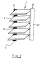
- Figure 1 shows a perspective view of a sun protection 1, in particular for windows or not shown Doors are determined.
- the sun protection 1 consists of one above the other arranged slats 2, which cover the window or door surfaces.
- the slats 2 are laterally in guides 3.1 and 3.2 kept, each on the outside of the window or door or in their Wall opening are arranged. It goes without saying that the individual slats 2 in the gathered state to a package in the upper Area of the guides 3.1 and 3.2 are collapsible.
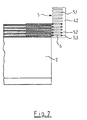
- the side guides 3.1 and 3.2 are made of rails 4.1 and 4.2, as shown in particular in FIG Top view can be seen, formed with longitudinal grooves 5, the rails 4.1 and 4.2 so in the window or Door opening are that the grooves 5. are arranged opposite one another. , This results in a guide in the window or door opening for ' the slats 2, the 'single slat 2 with lateral support elements 6 is equipped and the individual lamella 2 each is assigned a separate groove 5.
- each slat 2 with its support elements 6 each a groove 5 is assigned.
- the corresponding one above Slat 2 is assigned the downstream groove 5.1, 5.2, etc. so that the system continues to the rear.
- the profit tracks 4.1 and 4.2 are comb-like in cross section, wherein the individual grooves 5.1, 5.2, etc. each have a narrow design Rectangular cross-section.
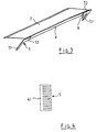
- the side Bracket elements 6 of the slats 2 have an angular shape, with a Leg 7.1 extending in the groove 5 and the other leg 7.2 at right angles to it. connected to the slat 2.
- the individual Slats 2 formed from a sheet metal strip, the one under inclined angle is connected to the support elements 6.
- the Sheet metal strip has a folded back strip 8 on which the Bracket elements 6 are attached.
Abstract
Description
Die Erfindung betrifft einen Sonnenschutz für Fenster oder Türen bestehend aus Lamellen, die die Fenster- oder Türfläche horizontalverlaufend abdecken, wobei die Lamellen in seitlichen Führungen außen am Fenster oder an der Tür geführt sind und wobei die einzelnen Lamellen im gerafften Zustand zu einem Paket zusammenlegbar sind.The invention relates to sun protection for windows or doors consisting of slats that run the window or door surface horizontally cover, the slats in lateral guides on the outside are led at the window or on the door and the individual Slats in the gathered state can be folded into a package.
Ein derartiger nach dem Stand der Technik, z.B. aus EP 0 296 420, bekannter Sonnenschutz für Fenster oder Türen wird auch als Außenraffstore bezeichnet, wobei insbesondere der Store aus einzelnen Lamellen besteht, die in seitlichen Führungen geführt werden. Die seitlichen Führungen sind dabei auf dem Fenster- oder Türrahmen befestigt, so daß die Einzellamellen unter einem Abstand zu der Tür- bzw. Fensterfläche herabgelassen bzw. hochgefahren werden können. Sind die Lamellen hochgefahren, so legen sich die Lamellen im oberen Fenstersturz zu einem Paket zusammen, welches von in einem am oberen Fenstersturz angeordneten Kasten aufgenommen wird. Such according to the prior art, e.g. from EP 0 296 420, known sun protection for Windows or doors are also known as external venetian blinds, whereby In particular, the store consists of individual slats that are arranged in the side Guided tours. The side guides are included attached to the window or door frame so that the individual slats lowered at a distance from the door or window surface or can be started up. If the slats are raised, lay them the slats in the upper lintel form a package, which is taken up in a box arranged in the upper lintel becomes.
Nachteil eines derartigen nach dem Stand der Technik bekannten Sonnenschutzes ist, daß er sehr aufwendig baut, da neben den Führungen an den seitlichen Fensterrahmen auch über die horizontale Erstreckung der Lamelle zusätzliche Bänder querverlaufend vorhanden sein müssen. damit für den heruntergefahrenen Lamellenvorhang die hinreichende Stabilität gegeben ist. Dies ist insbesondere im Hinblick auf Windeinflüsse erforderlich, damit ein Flattern der Lamellen verhindert wird, und somit Geräuschentwicklungen unterbunden werden. Zur Sicherung des Sonnenschutzes vor Windeinflüssen werden auch beispielsweise zusätzliche Steuervorrichtungen vorgesehen, die auf die Windgeschwindigkeit hin reagieren, so daß bei einer Überschreitung einer bestimmten Windgeschwindigkeit der Raffstore selbstätig einfährt. Derartige Raffstore-Anlagen bauen daher sehr aufwendig mit der Folge, daß sie äußerst kostenaufwendig sind.Disadvantage of such a sun protection known from the prior art is that he builds very complex, because in addition to the guides on the side window frames also over the horizontal extent additional strips must run across the slat. this is sufficient for the lowered slat curtain Stability is given. This is especially true with regard to wind influences required to prevent the slats from fluttering will be prevented, and thus noise development. To secure of sun protection from wind influences are also, for example additional control devices are provided that are based on the wind speed respond so that when a certain wind speed of the Venetian blind automatically. Such venetian blind systems are therefore very expensive to build, with the result that that they are extremely expensive.
Es ist daher die Aufgabe der Erfindung vor dem aufgezeigten Stand der Technik hier insbesondere einen Sonnenschutz bereitzustellen, der bei einer kostengünstigen Herstellung ein stabiles Führungssystem für die einzelnen Lamellen bietet, welches unter Windeinflüssen die Lamellen geräuschlos hält.It is therefore the object of the invention before the shown state of the Technology here in particular to provide sun protection that at an inexpensive production a stable guidance system for the individual slats, which under the wind influences the slats keeps silent.
Diese Aufgabe wird erfindungsgemäß dadurch gelöst, daß die seitlichen Führungen aus Profilschienen mit aus mehreren längsverlaufenden Nuten gebildet sind, und wobei zwischen den gegenüberliegenden Nuten jeweils Lamellen'mit seitlichen Halterungselementen verschiebbar angeordnet sind, wobei jeweils einer Lamelle eine Nut zugeordnet ist. Diese Ausbildung gewährleistet einerseits ein sehr sicheres Führungssystem in den seitlichen Berei chen des Fensters oder der Tür, weil1 jede einzelne Lamelle in einer gesonderten Nut geführt ist. Somit ist jeder Lamelle mit ihren seitlichen Halterungselementen eine Nut zugeordnet, in der sich die Lamelle auf- bzw. abwärts bewegen läßt. Zu dem erweist sich dieses System als kostengünstig, da die den Sonnenschutz umfassenden Teile einfach ausgebildet sind, was letztendlich auch die Störanfälligkeit eines derartigen Systems unterbindet. This object is achieved in that the lateral Guides made of profiled rails with several longitudinal grooves are formed, and being between the opposite grooves each Slats' with lateral mounting elements slidably arranged are, a groove being assigned to each lamella. On the one hand, this training ensures a very secure management system in the side areas of the window or door because 1 each individual slat is guided in a separate groove. So is a groove is assigned to each lamella with its lateral mounting elements, in which the slat can be moved up or down. To this system proves to be cost-effective because it provides sun protection comprehensive parts are simply formed, which ultimately the susceptibility to malfunction of such a system is also prevented.
Aufgrund der stabilen Halterung in der zugeordneten Nut ist die Einzellamelle stabil gelagert, so daß hinsichtlich auftretender Windeinflüsse keine Faltungen des Lamellenblechs erfolgen kann.Due to the stable mounting in the assigned groove, the single lamella is stably stored so that with regard to wind influences no folding of the lamella sheet can take place.
In vorteilhafter Weiterbildung der Erfindung sind die Profilschienen im Querschnitt kammartig ausgebildet, wobei die einzelnen Nuten einen schmal ausgebildeten.Rechteck-Querschnitt aufweisen. Insbesondere der Rechteck-Querschnitt ermöglicht für die seitlichen Halterungen eine sichere Führung, so daß im Bereich des Rechteckquerschnittes ein Verkanten der Halterungselemente ausgeschlossen werden kann. Hierzu weisen die seitlichen Halterungselemente der Lamellen eine Winkelform auf, wobei ein Schenkel in der Nut verlaufend und der andere Schenkel rechtwinklig dazu mit der Lamelle verbunden ist.In an advantageous development of the invention, the rails are formed like a comb in cross section, the individual grooves one have a narrow cross-section. Especially the Rectangular cross-section enables a for the side brackets secure guidance, so that tilting in the area of the rectangular cross-section the bracket elements can be excluded. To do this the lateral support elements of the slats have an angular shape with one leg running in the groove and the other leg is connected at right angles to the slat.
Nach einer besonders vorteilhaften Weiterbildung der Erfindung ist die einzelne Lamelle aus einem Blechstreifen gebildet, der unter ei.nem geneigten Winkel mit den Halterungselementen verbunden ist. Somit wird durch die einzelnen übereinander angeordneten Lamellen eine Blendwirkung erreicht, die eine direkte Sonnenstrahlung in die Räumlichkeiten unterbindet. Hierbei weist der Blechstreifen einen gefalteten Rückenstreifen auf, an dem die Halterungselemente befestigt sind. In Weiterbildung der Erfindung ist die Vorderkante des Blechstreifens unter einem steileren Winkel gefaltet, was insbesondere den Strahlungseinfallswinkel des Lichtes zunehmend abblendet.According to a particularly advantageous development of the invention the single lamella is formed from a sheet metal strip, which under a egg inclined angle is connected to the mounting elements. Consequently becomes one by the individual slats arranged one above the other Glare achieved that direct sunlight into the premises in derogation. Here, the sheet metal strip has a folded Back strip on which the mounting elements are attached are. In a further development of the invention, the front edge of the metal strip is folded at a steeper angle, which in particular the The angle of incidence of the light increasingly dims.
Nach einer bevorzugten Ausführungsform der Erfindung sind die einzelnen Lamellen in den Nuten mittels Fixierelementen festsetzbar. Somit kann insbesondere der zwischen den einzelnen zueinander angeordneten Lamellen entsprechende Fixierabstand frei gewählt werden. In der vordersten Nut ist die unterste Lamelle in der Profilschiene angeordnet, wobei sich dann treppenartig die anderen darüberliegenden Lamellen bis zur oberen Fenster- oder Türkante hin aufbauen. Hierbei ist auch .denkbar, daß die Lamellen mittels eines Antriebs in den Nuten verschiebbar sind. According to a preferred embodiment of the invention, the individual Slats can be fixed in the grooves using fixing elements. Consequently can in particular be arranged between each other The corresponding fixing distance between the slats can be freely selected. In the front The bottom lamella is arranged in the groove, where the other slats above are then stepped Build up to the upper edge of the window or door. Here is also .thinkable that the slats can be moved in the grooves by means of a drive are.
Nach einer besonders vorteilhaften Weiterbildung der Erfindung weisen . bei der Führung mehrerer Lamellen die geführten Schenkel in der Nut unterschiedliche Längen auf. Somit wird erreicht, daß bei der Anordnung mehrerer geführter Lamellen in einer Nut diese im heruntergelassenen Zustand des Sonnenschutzes ebenfalls entsprechend auf Distanz zueinander gehalten werden können. Hierzu korrespondieren die.unterschiedlich lang ausgebildeten Schenkel mit in der Nut entsprechend angeordneten Fixierungselementen.According to a particularly advantageous development of the invention , when guiding several slats, the guided legs in the groove different lengths. It is thus achieved that the arrangement several guided slats in a groove these in the lowered Condition of the sun protection also at a distance can be held to each other. These correspond differently long legs with corresponding in the groove arranged fixation elements.
Ein Ausführungsbeispiel der Erfindung wird anhand der nachstehenden Figuren 1 - 5 näher erläutert; dabei zeigen:
- Figur 1:
- Eine perspektivische Vorderansicht des erfindungsgemäßen Sonnenschutzes;
- Figur 2:
- Eine teilweise geschnittene Draufsicht gemäß der
Schnittlinie II - II in
Figur 1; - Figur 3:
- Eine perspektivische Rückansicht einer Lamelle;
- Figur 4:
- Eine.Einzeldarstellung in Draufsicht auf die Profilschiene mit den U-förmigen Einnehmungen;
- Figur 5:
- Eine weitere perspektivische Darstellung des Sonnenschutzes mit mehreren in einer Nut geführten Lamellen.
- Figure 1:
- A perspective front view of the sun protection according to the invention;
- Figure 2:
- A partially sectioned plan view according to section line II - II in Figure 1;
- Figure 3:
- A perspective rear view of a slat;
- Figure 4:
- A detailed view in top view of the profile rail with the U-shaped recesses;
- Figure 5:
- Another perspective view of the sun protection with several slats guided in a groove.
Die Figur 1 zeigt in der perspektivischen Darstellung einen Sonnenschutz
1, der insbesondere für nicht näher dargestellte Fenster oder
Türen bestimmt.ist. Hierbei besteht der Sonnenschutz 1 aus übereinander
angeordneten Lamellen 2, die die Fenster- oder Türflächen abdecken.
Dabei sind die Lamellen 2 seitlich in Führungen 3.1 und 3.2
gehalten, die jeweils außen am Fenster oder der Tür bzw. in deren
Maueröffnung angeordnet sind. Es versteht sich von selbst, daß die
einzelnen Lamellen 2 im gerafften Zustand zu einem Paket im oberen
Bereich der Führungen 3.1 und 3.2 zusammenlegbar sind. Figure 1 shows a perspective view of a
Erfindungsgemäß sind die seitlichen Führungen 3.1 und 3.2 aus Profilschienen
4.1 und 4.2, wie sie insbesondere in der Figur 4 in der
Draufsicht zu erkennen sind, mit längsverlaufenden Nuten 5 gebildet,
wobei die Profilschienen 4.1 und 4.2 derart in der Fenster- oder
Türöffnung liegen, daß die Nuten 5.gegenüberliegend angeordnet sind.
. Somit ergibt sich in der Fenster- oder Türöffnung eine Führung für'
die Lamellen 2, wobei die 'einzelne Lamelle 2 mit seitlichen Halterungselementen
6 ausgestattet ist und die Einzellamelle 2 jeweils
einer gesonderten Nut 5 zugeordnet ist. Zum besseren Verständnis der
Führungssituation der Lamellen 2 in den Profilschienen 4.1 und 4.2
ze.igt die Figur 2, daß jeder Lamelle 2 mit ihren Halterungselementen
6 jeweils eine Nut 5 zugeordnet ist. Der entsprechenden darüberliegenden
Lamelle 2 ist die nachgeschaltete Nut 5.1, 5.2, usw. zugeordnet,
so daß sich das System nach hinten hin fortsetzt.According to the side guides 3.1 and 3.2 are made of rails
4.1 and 4.2, as shown in particular in FIG
Top view can be seen, formed with
Wie insbesondere aus der Figur 2.und 4 zu erkennen ist, sind die Profitschienen
4.1 und 4.2 im Querschnitt kammartig ausgebildet, wobei
die einzelnen Nuten 5.1, 5.2, usw. jeweils einen schmal ausgebildeten
Rechteckquerschnitt aufweisen. Wie insbesondere aus der perspektivischen
Rückansicht der. Figur 3 zu erkennen ist, weisen die seitlichen
Halterungselemente 6 der Lamellen 2 eine Winkelform auf, wobei ein
Schenkel 7.1 in der Nut 5 verlaufend und der andere Schenkel 7.2
rechtinklig dazu.mit der Lamelle 2 verbunden ist. Dabei sind die einzelnen
Lamellen 2 aus einem Blechstreifen gebildet, der unter einem
geneigten Winkel mit den Halterungselementen 6 verbunden ist. Der
Blechstreifen weist einen gefalteten Rückenstreifen 8 auf, an dem die
Halterungselemente 6 befestigt sind. In Weiterbildung der Erfindung
ist die Vorderkante des Blechstreifens unter einem steileren Winkel
gefaltet. In vorteilhafter Weiterbildung, um die Lamellen 2 mit ihren
Halterungselementen 6 in einem bestimmten Niveau zu halten, sind in
die Nuten 5 nicht näher dargestellte Fixierelemente einsetzbar. Somit
werden die Lamellen 2 auf einem Niveau gehalten, wobei sie, um den
Querschnitt freizugeben, nach oben hin frei verschiebbar sind. Dies
kann dann beispielsweise mit einem im oberen Bereich der Führungen
3.1 und 3.2 angeordneten Antrieb erfolgen, der die einzelnen Lamellen
2 zu einem Paket zusammenfährt. As can be seen in particular from FIGS. 2 and 4, there are the profit tracks
4.1 and 4.2 are comb-like in cross section, wherein
the individual grooves 5.1, 5.2, etc. each have a narrow design
Rectangular cross-section. As especially from the perspective
Rear view of the. Figure 3 can be seen, the
Nach einer besonders vorteilhaften Weiterbildung der Erfindung, dargestellt
in der Figur 5, weisen bei der Führung mehrerer Lamellen 2
die geführten Schenkel 7.1 in der Nut 5 unterschiedliche Längen auf.
Somit wird erreicht, daß bei der Anordnung mehrerer geführter Lamellen
2 in einer Nut 5 diese im heruntergelassenen Zustand des Sonnenschutzes
ebenfalls entsprechend auf Distanz zueinander gehalten werden.
Hierzu korrespondieren die unterschiedlich lang ausgebildeten
Schenkel 7.1 mit in der Nut 5 entsprechend angeordneten nicht näher
dargestellten Fixierungselementen.According to a particularly advantageous development of the invention
in FIG. 5, when guiding a plurality of
Claims (10)
- Solar protection for windows or doors comprising slats which, running horizontally, cover the surface of the window or door, with the slats being guided in lateral guides on the outside of the window or door, and with the individual slats when gathered up folding to form a stack, characterised in that the lateral guides (3.1, 3.2) are formed from profile rails (4.1. 4.2) having several longitudinally running, separate grooves (5) opposite to one another, and with slats (2) having lateral holding elements (6) being displaceably located in each case between the separate grooves (5) opposite to one another, with one of the separate grooves (5) opposite to one another being allocated in each case to one slat (2) in each of the two guides (3.1, 3.2).
- Solar protection as claimed in Claim 1, characterised in that the profile rails (4.1, 4.2) have a comb-like configuration in cross section, with the individual grooves (5.1, 5.2) having a narrowly configured rectangular cross section.
- Solar protection as claimed in Claims 1 and 2, characterised in that the lateral holding elements (6) of the slats (2) have an angular form, with one leg (7.1) running in the groove (5) and the other leg (7.2) at right angles thereto being connected to the slat (2).
- Solar protection as claimed in Claim 3, characterised in that the individual slat (2) is formed from a sheet-metal strip which is connected at an oblique angle with the holding elements (6).
- Solar protection as claimed in Claim 4, characterised in that the sheet-metal strip has a folded back strip (8) to which the holding elements (6) are affixed.
- Solar protection as claimed in Claims 4 and 5, characterised in that the front edge of the sheet-metal strip is folded at a more acute angle.
- Solar protection as claimed in one or more of the preceding Claims 1 to 6, characterised in that the individual slats (2) can be fixed in the grooves (5) by means of fixing elements.
- Solar protection as claimed in Claim 7, characterised in that the slats (2) can be displaced in the grooves (5) by means of a drive.
- Solar protection as claimed in one or more of the preceding Claims 1 to 8, characterised in that when guiding several slats (2) the guided legs (7.1) in the groove (5) have various lengths.
- Solar protection as claimed in Claim 9, characterised in that the legs (7.1) which are formed with various lengths correspond with fixing elements which are located accordingly in the groove (5).
Applications Claiming Priority (4)
| Application Number | Priority Date | Filing Date | Title |
|---|---|---|---|
| DE29719648U | 1997-11-05 | ||
| DE29719648 | 1997-11-05 | ||
| DE29802244U | 1998-02-10 | ||
| DE29802244U DE29802244U1 (en) | 1997-11-05 | 1998-02-10 | Sun protection for windows or doors |
Publications (3)
| Publication Number | Publication Date |
|---|---|
| EP0915228A2 EP0915228A2 (en) | 1999-05-12 |
| EP0915228A3 EP0915228A3 (en) | 2001-01-17 |
| EP0915228B1 true EP0915228B1 (en) | 2004-01-28 |
Family
ID=26060869
Family Applications (1)
| Application Number | Title | Priority Date | Filing Date |
|---|---|---|---|
| EP98121024A Expired - Lifetime EP0915228B1 (en) | 1997-11-05 | 1998-11-05 | Solar protection for windows or doors |
Country Status (4)
| Country | Link |
|---|---|
| EP (1) | EP0915228B1 (en) |
| AT (1) | ATE258643T1 (en) |
| CZ (1) | CZ295389B6 (en) |
| PL (1) | PL189014B1 (en) |
Families Citing this family (1)
| Publication number | Priority date | Publication date | Assignee | Title |
|---|---|---|---|---|
| DE102015000173A1 (en) * | 2015-01-02 | 2016-07-07 | D & M Rolladentechnik Gmbh | External Blinds |
Family Cites Families (1)
| Publication number | Priority date | Publication date | Assignee | Title |
|---|---|---|---|---|
| DE3876309T2 (en) * | 1987-06-22 | 1993-06-24 | Parma Developments Ltd | SHUTTER. |
-
1998
- 1998-11-05 AT AT98121024T patent/ATE258643T1/en not_active IP Right Cessation
- 1998-11-05 PL PL98329556A patent/PL189014B1/en not_active IP Right Cessation
- 1998-11-05 EP EP98121024A patent/EP0915228B1/en not_active Expired - Lifetime
- 1998-11-05 CZ CZ19983595A patent/CZ295389B6/en not_active IP Right Cessation
Also Published As
| Publication number | Publication date |
|---|---|
| PL329556A1 (en) | 1999-05-10 |
| EP0915228A2 (en) | 1999-05-12 |
| CZ295389B6 (en) | 2005-07-13 |
| EP0915228A3 (en) | 2001-01-17 |
| ATE258643T1 (en) | 2004-02-15 |
| CZ359598A3 (en) | 1999-05-12 |
| PL189014B1 (en) | 2005-06-30 |
Similar Documents
| Publication | Publication Date | Title |
|---|---|---|
| EP1006012B1 (en) | Roller blind for vehicle | |
| EP0338362B1 (en) | Sun-protection arrangement | |
| DE2339596A1 (en) | ROLLER CURTAIN ARRANGEMENT | |
| DE69807438T3 (en) | UNIVERSAL MOUNTING AND PARALLEL GUIDE FOR WINDOW SHIELDING | |
| EP0377778A1 (en) | Louver blind with vertical louver slats | |
| DE3039594C2 (en) | Louvre door made of strips of flexible plastic material | |
| CH670478A5 (en) | ||
| DE3822378A1 (en) | Window blind for a motor vehicle | |
| DE202006009738U1 (en) | Guide arrangement for shading or insect protection elements for windows, doors and openings comprises a movable bracket provided with cross-over guide grooves for cables or a single endless cable | |
| DE3511246A1 (en) | Screening or protecting device for wall openings or the like, in particular a roller shutter or a blind | |
| DE2312661B2 (en) | Pleated blind | |
| DE202007014450U1 (en) | Guide bar for windows and doors | |
| EP1489258A1 (en) | Horizontal blind | |
| DE4034614C2 (en) | ||
| EP0915228B1 (en) | Solar protection for windows or doors | |
| DE3526745C2 (en) | ||
| DE102015122723A1 (en) | Sun protection system | |
| DE3225099C2 (en) | ||
| DE202007017061U1 (en) | Universal frame for curtains or roller blinds | |
| DE3032003A1 (en) | Folding venetian blind mounting - has guide rail with strip channels and blind slot in top and bottom retaining battens | |
| EP0254896A2 (en) | Roll-screen for mobil-home window | |
| DE3700745A1 (en) | Folding net curtain (folding blind) for interior shading of in particular conservatories or the like | |
| EP0132497B1 (en) | Insulating blind | |
| EP0738821A2 (en) | Darkening/shadening device | |
| DE19709478C2 (en) | Venetian blind |
Legal Events
| Date | Code | Title | Description |
|---|---|---|---|
| PUAI | Public reference made under article 153(3) epc to a published international application that has entered the european phase |
Free format text: ORIGINAL CODE: 0009012 |
|
| AK | Designated contracting states |
Kind code of ref document: A2 Designated state(s): AT BE DE FR IT NL |
|
| AX | Request for extension of the european patent |
Free format text: AL;LT;LV;MK;RO;SI |
|
| PUAL | Search report despatched |
Free format text: ORIGINAL CODE: 0009013 |
|
| AK | Designated contracting states |
Kind code of ref document: A3 Designated state(s): AT BE CH CY DE DK ES FI FR GB GR IE IT LI LU MC NL PT SE |
|
| AX | Request for extension of the european patent |
Free format text: AL;LT;LV;MK;RO;SI |
|
| 17P | Request for examination filed |
Effective date: 20010227 |
|
| AKX | Designation fees paid |
Free format text: AT BE DE FR IT NL |
|
| AXX | Extension fees paid |
Free format text: LV PAYMENT 20010227;RO PAYMENT 20010227 |
|
| GRAP | Despatch of communication of intention to grant a patent |
Free format text: ORIGINAL CODE: EPIDOSNIGR1 |
|
| GRAS | Grant fee paid |
Free format text: ORIGINAL CODE: EPIDOSNIGR3 |
|
| GRAA | (expected) grant |
Free format text: ORIGINAL CODE: 0009210 |
|
| AK | Designated contracting states |
Kind code of ref document: B1 Designated state(s): AT BE DE FR IT NL |
|
| AX | Request for extension of the european patent |
Extension state: LV RO |
|
| REF | Corresponds to: |
Ref document number: 59810656 Country of ref document: DE Date of ref document: 20040304 Kind code of ref document: P |
|
| PGFP | Annual fee paid to national office [announced via postgrant information from national office to epo] |
Ref country code: DE Payment date: 20040915 Year of fee payment: 7 |
|
| PGFP | Annual fee paid to national office [announced via postgrant information from national office to epo] |
Ref country code: FR Payment date: 20040928 Year of fee payment: 7 |
|
| PGFP | Annual fee paid to national office [announced via postgrant information from national office to epo] |
Ref country code: NL Payment date: 20040930 Year of fee payment: 7 |
|
| ET | Fr: translation filed | ||
| PGFP | Annual fee paid to national office [announced via postgrant information from national office to epo] |
Ref country code: BE Payment date: 20041119 Year of fee payment: 7 |
|
| PGFP | Annual fee paid to national office [announced via postgrant information from national office to epo] |
Ref country code: AT Payment date: 20041125 Year of fee payment: 7 |
|
| PLBE | No opposition filed within time limit |
Free format text: ORIGINAL CODE: 0009261 |
|
| STAA | Information on the status of an ep patent application or granted ep patent |
Free format text: STATUS: NO OPPOSITION FILED WITHIN TIME LIMIT |
|
| 26N | No opposition filed |
Effective date: 20041029 |
|
| PG25 | Lapsed in a contracting state [announced via postgrant information from national office to epo] |
Ref country code: IT Free format text: LAPSE BECAUSE OF NON-PAYMENT OF DUE FEES Effective date: 20051105 Ref country code: AT Free format text: LAPSE BECAUSE OF NON-PAYMENT OF DUE FEES Effective date: 20051105 |
|
| PG25 | Lapsed in a contracting state [announced via postgrant information from national office to epo] |
Ref country code: BE Free format text: LAPSE BECAUSE OF NON-PAYMENT OF DUE FEES Effective date: 20051130 |
|
| PG25 | Lapsed in a contracting state [announced via postgrant information from national office to epo] |
Ref country code: NL Free format text: LAPSE BECAUSE OF NON-PAYMENT OF DUE FEES Effective date: 20060601 Ref country code: DE Free format text: LAPSE BECAUSE OF NON-PAYMENT OF DUE FEES Effective date: 20060601 |
|
| PG25 | Lapsed in a contracting state [announced via postgrant information from national office to epo] |
Ref country code: FR Free format text: LAPSE BECAUSE OF NON-PAYMENT OF DUE FEES Effective date: 20060731 |
|
| NLV4 | Nl: lapsed or anulled due to non-payment of the annual fee |
Effective date: 20060601 |
|
| REG | Reference to a national code |
Ref country code: FR Ref legal event code: ST Effective date: 20060731 |
|
| BERE | Be: lapsed |
Owner name: *HENKENJOHANN JOHANN Effective date: 20051130 |