EP0913617B1 - Schnellverbindungs- und trennkupplung für elektropumpen und leitungen für eine scheibenreinigungsanlage eines kraftfahrzeugs - Google Patents
Schnellverbindungs- und trennkupplung für elektropumpen und leitungen für eine scheibenreinigungsanlage eines kraftfahrzeugs Download PDFInfo
- Publication number
- EP0913617B1 EP0913617B1 EP97928279A EP97928279A EP0913617B1 EP 0913617 B1 EP0913617 B1 EP 0913617B1 EP 97928279 A EP97928279 A EP 97928279A EP 97928279 A EP97928279 A EP 97928279A EP 0913617 B1 EP0913617 B1 EP 0913617B1
- Authority
- EP
- European Patent Office
- Prior art keywords
- nozzle body
- disconnection
- connection
- connecting body
- disconnection device
- Prior art date
- Legal status (The legal status is an assumption and is not a legal conclusion. Google has not performed a legal analysis and makes no representation as to the accuracy of the status listed.)
- Expired - Lifetime
Links
- 238000005406 washing Methods 0.000 title description 2
- 230000000295 complement effect Effects 0.000 claims abstract description 6
- 238000004140 cleaning Methods 0.000 claims description 9
- 230000005489 elastic deformation Effects 0.000 claims description 9
- 239000007788 liquid Substances 0.000 claims description 9
- 238000009434 installation Methods 0.000 claims description 8
- 239000000463 material Substances 0.000 description 3
- 238000002347 injection Methods 0.000 description 1
- 239000007924 injection Substances 0.000 description 1
- 238000003780 insertion Methods 0.000 description 1
- 230000037431 insertion Effects 0.000 description 1
- 239000000314 lubricant Substances 0.000 description 1
- 230000001050 lubricating effect Effects 0.000 description 1
- 238000012423 maintenance Methods 0.000 description 1
- 238000000926 separation method Methods 0.000 description 1
- 239000000243 solution Substances 0.000 description 1
Images

Classifications
-
- F—MECHANICAL ENGINEERING; LIGHTING; HEATING; WEAPONS; BLASTING
- F16—ENGINEERING ELEMENTS AND UNITS; GENERAL MEASURES FOR PRODUCING AND MAINTAINING EFFECTIVE FUNCTIONING OF MACHINES OR INSTALLATIONS; THERMAL INSULATION IN GENERAL
- F16L—PIPES; JOINTS OR FITTINGS FOR PIPES; SUPPORTS FOR PIPES, CABLES OR PROTECTIVE TUBING; MEANS FOR THERMAL INSULATION IN GENERAL
- F16L37/00—Couplings of the quick-acting type
- F16L37/08—Couplings of the quick-acting type in which the connection between abutting or axially overlapping ends is maintained by locking members
- F16L37/084—Couplings of the quick-acting type in which the connection between abutting or axially overlapping ends is maintained by locking members combined with automatic locking
- F16L37/092—Couplings of the quick-acting type in which the connection between abutting or axially overlapping ends is maintained by locking members combined with automatic locking by means of elements wedged between the pipe and the frusto-conical surface of the body of the connector
- F16L37/0925—Couplings of the quick-acting type in which the connection between abutting or axially overlapping ends is maintained by locking members combined with automatic locking by means of elements wedged between the pipe and the frusto-conical surface of the body of the connector with rings which bite into the wall of the pipe
-
- F—MECHANICAL ENGINEERING; LIGHTING; HEATING; WEAPONS; BLASTING
- F16—ENGINEERING ELEMENTS AND UNITS; GENERAL MEASURES FOR PRODUCING AND MAINTAINING EFFECTIVE FUNCTIONING OF MACHINES OR INSTALLATIONS; THERMAL INSULATION IN GENERAL
- F16L—PIPES; JOINTS OR FITTINGS FOR PIPES; SUPPORTS FOR PIPES, CABLES OR PROTECTIVE TUBING; MEANS FOR THERMAL INSULATION IN GENERAL
- F16L33/00—Arrangements for connecting hoses to rigid members; Rigid hose-connectors, i.e. single members engaging both hoses
- F16L33/22—Arrangements for connecting hoses to rigid members; Rigid hose-connectors, i.e. single members engaging both hoses with means not mentioned in the preceding groups for gripping the hose between inner and outer parts
- F16L33/225—Arrangements for connecting hoses to rigid members; Rigid hose-connectors, i.e. single members engaging both hoses with means not mentioned in the preceding groups for gripping the hose between inner and outer parts a sleeve being movable axially
-
- F—MECHANICAL ENGINEERING; LIGHTING; HEATING; WEAPONS; BLASTING
- F16—ENGINEERING ELEMENTS AND UNITS; GENERAL MEASURES FOR PRODUCING AND MAINTAINING EFFECTIVE FUNCTIONING OF MACHINES OR INSTALLATIONS; THERMAL INSULATION IN GENERAL
- F16L—PIPES; JOINTS OR FITTINGS FOR PIPES; SUPPORTS FOR PIPES, CABLES OR PROTECTIVE TUBING; MEANS FOR THERMAL INSULATION IN GENERAL
- F16L37/00—Couplings of the quick-acting type
- F16L37/08—Couplings of the quick-acting type in which the connection between abutting or axially overlapping ends is maintained by locking members
- F16L37/12—Couplings of the quick-acting type in which the connection between abutting or axially overlapping ends is maintained by locking members using hooks, pawls, or other movable or insertable locking members
- F16L37/138—Couplings of the quick-acting type in which the connection between abutting or axially overlapping ends is maintained by locking members using hooks, pawls, or other movable or insertable locking members using an axially movable sleeve
-
- B—PERFORMING OPERATIONS; TRANSPORTING
- B60—VEHICLES IN GENERAL
- B60S—SERVICING, CLEANING, REPAIRING, SUPPORTING, LIFTING, OR MANOEUVRING OF VEHICLES, NOT OTHERWISE PROVIDED FOR
- B60S1/00—Cleaning of vehicles
- B60S1/02—Cleaning windscreens, windows or optical devices
- B60S1/46—Cleaning windscreens, windows or optical devices using liquid; Windscreen washers
- B60S1/48—Liquid supply therefor
- B60S1/50—Arrangement of reservoir
Definitions
- the object of the invention is a quick connection and disconnection device for electric pumps and tubes of automobile vehicle windscreen washer installations.
- the device of the invention is applicable to the outlet nozzle of windscreen washer electric pumps and any other of the elements habitually used in automobile vehicle windscreen washer installations such as attachment and tap-off accessories, jets, etc.
- washing of the glazed surfaces of automobile vehicles is carried out using factory-fitted means which generally include a cleaning liquid reservoir, an electric pump generally attached to said reservoir, and a plurality of flexible tubes which link said electric pump with jets which project the cleaning liquid against the glazed surfaces at the pressure and flow required in each particular case.
- the electric pump essentially comprises a sucking and forcing pump made up of an forcing chamber in which is fitted a sucking and forcing turbine, with input of cleaning liquid to the forcing chamber being implemented by means of an axial sucking extension and output of cleaning liquid from said chamber being implemented through an outlet nozzle tangentially mounted with respect to same.
- the outlet nozzle has its free end designed to receive a corresponding end of flexible tube, said design arrangement consisting in a truncated-end termination in which the larger base forms a perimetric projection, with connection under pressure of said end of tube to the outlet nozzle, in such a way that by elastic reaction of the tube material said end presses on the exterior surface of the outlet nozzle to lend the connection a certain leaktightness.
- the mode of flexible tube connection described above has the following main disadvantages.
- the location of the electric pump and accessibility to same are frequently a considerable hindrance to implementation of connection or disconnection of the tube, which increases the cost of both the windscreen washer installation and its maintenance.
- the insertion under pressure of the outlet nozzle into the tube generally calls for the use of lubricating materials such as greases applied onto the nozzle, which under certain circumstances, such as when too much of said lubricants is applied, can lead to blockage of the tube, preventing free circulation of cleaning liquid.
- connection of a flexible tube to the outlet nozzle of an electric pump is by extension entirely applicable to connection of a tube of this type to a cleaning liquid inlet or outlet nozzle of any of the elements habitually used in windscreen washer installations, such as attachment and/or tap-off elements and jets.
- a quick connection and disconnection device of new structure and operation for electric pumps and tubes of automobile vehicle windscreen washer installations is made known herein in order to provide a solution to the above-described disadvantages generally presented in connection and disconnection of flexible tubes to and from nozzles.
- the quick connection and disconnection device of the invention includes a nozzle body and a connecting body coaxially mounted and permanently attached and capable of sliding longitudinally in both directions one with respect to the other, with both bodies having a respective axial passage, respective and complementary attachment means so designed that the connecting body has two working positions, a first position or disconnection position in which one end of flexible tube, traversing the axial passage of the connecting body, fits into the axial passage of the nozzle body, and a second position, or connection position, in which said end of tube is attached securely to the nozzle and connecting bodies by the action of fixing means which both bodies have respectively and in complementary fashion, while the nozzle body has leaktightness means which, once said tube end has been connected, are destined to prevent leakage of cleaning liquid.
- the fast connection and disconnection device of the invention further comprises attachment means which include in the nozzle body and externally, two perimetral linking grooves, for connection and disconnection respectively, separated by a wall of convex-curved outline, and at one end of the connecting body, a plurality of longitudinal grooves which, starting from the edge of said end, form attaching arms having to their interior attachment projections designed to be housed with a snug fit in the connecting or disconnecting groove, all being adapted in such a way that the passage of the connecting body from the disconnection position to the connection position, and vice-versa, is carried out by means of a double elastic deformation of the attachement arms.
- the fixing means include, in the axial passage of the nozzle body, a first cylindrical portion or interior portion whose diameter coincides with that of the interior of said end of flexible tube, a second intermediate cylindrical portion of larger diameter than that of the interior portion which attaches to it and forming a seat on which said end of tube can rest, a third intermediate truncated-cone portion whose smaller base attaches to said second portion, and a fourth cylindrical portion which attaches to the larger base of said third truncated-cone portion to form an opening mouth, and on the connecting body, interior and tangentially mounted with respect to its axial passage, a plurality of fixing arms which are the same as each other and regularly distributed and have in the interior of their free ends a fixing projection, all being adapted in such a way that, during the passage of the connecting body from the disconnection position to the connection position, and vice-versa, a simple elastic deformation of the fixing arms is produced upon their sliding over the t
- the leaktightness means include, on the nozzle body and on the second intermediate cylindrical portion of the axial passage, a perimetric groove on which there is a leaktightness seal.
- At least one of the attaching arms of the connecting body has a handgrip projection.
- the nozzle body includes a tubular axial extension which is tangentially linked hydraulically with the forcing chamber of an electric sucking and forcing pump.
- the nozzle body includes a tubular axial extension by which it is attached to another nozzle body in such a way as to permit the hydraulic connection of two ends of respective flexible tubes.
- the nozzle body includes a tubular axial extension which attaches to a jet body to establish hydraulic communication with the jet projecting means.
- the functioning of the device of the invention whose characteristics have been described is of extraordinary simplicity and is described below.
- the device is supplied ex-works with the connecting body attached to the nozzle body and occupying the disconnection position, in which position the attachment projections of the attachment arms are in the disconnection attaching groove of the nozzle body, thereby preventing any accidental separation of the two bodies.
- the user has simply to insert the end of a flexible tube through the axial passage of the connecting body until said end rests on the seat formed by attachment of the first and second portions of the axial passage of the nozzle body, and then move the connecting body from the disconnection position to the connection position by making the fixing arms slide on the truncated-cone portion of the axial passage of the nozzle body, this sliding causing an elastic deformation of the fixing arms which, by drawing towards each other, press by means of their fixing projections on the tube and fix its position; there arises simultaneously a double elastic deformation of the attaching arms of the connecting body, in such a way that the attaching projections go into the attaching groove and fix the position of the attaching body.
- Disconnection of the tube end simply requires movement of the connecting body from the connection to the disconnection position and, by elastic reaction of the fixing arms sliding on said truncated-cone portion, causes the return to their initial position of said fixing arms whose fixing projections cease to exercise pressure on the tube end, which is released and so can be withdrawn easily from the device through the axial passage of the connecting body; there arises simultaneously a double elastic deformation of the attaching arms, leaving their attaching projections in the disconnection attaching groove in such a way that the quick connection and disconnection device of the invention is left in the initial position described above.
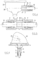
- Figures 1 to 3 show how the quick connection and disconnection device 1 of the invention comprises a nozzle body 2 and a connecting body 3 which can be coupled together and are preferably obtained by injection of plastic material.
- the nozzle body 2 is of generally cylindrical shape and includes a cylindrical axial attaching extension 4.
- the attaching extension 4 has two equal perimetric attaching grooves, a first connection attaching groove 5 and a second disconnection attaching groove 6.
- Both grooves 5, 6 have a cross section of generally U-shaped outline and are at a relatively short distance from each other, while the wall 7 which separates them has a cross section of convex-curved outline.
- the nozzle body 2 has an axial passage 8 in which can be distinguished: a first cylindrical portion or interior portion 9 whose diameter coincides with that of the end of a flexible tube 10; a second intermediate cylindrical portion 11 of larger diameter whose attachment with the interior portion 9 forms a seat 12 designed to support the end of the tube 10 as shown in Figure 3; a third intermediate truncated-cone portion 13 whose smaller base attaches to the second intermediate cylindrical portion 11; and a fourth cylindrical portion 14 having the same diameter as that of the larger base of the intermediate truncated-cone portion 13 which forms an opening 15 of the attaching extension 4.
- the second intermediate cylindrical portion 11 has a perimetric groove 16 in which there is a leaktightness O-ring.
- the connecting body 3 is of generally hollow cylindrical shape open at one of its ends, marked with reference number 18, while its other end, the closed end 19, has an axial passage 20 through which the end of the tube 10 can slide in both directions, as shown in Figure 2.
- the connecting body 3 has on its open end 18 and starting from its edge 21, four equal grooves 22 running longitudinally and regularly distributed which form corresponding attachment arms 23 to the interior of which are respective attachment projections 24, so designed that they can be housed with a snug fit in the connection 5 or disconnection 6 attachment groove 5 of the nozzle body 2.
- the functioning of the quick connection and disconnection device 1 of the invention described as an example of embodiment is now described.
- the device 1 is supplied ex-works as shown in Figure 1; with the nozzle 2 and connecting 3 bodies attached in such a way that the four attachment projections 24 of the attaching arms 23 of the connecting body 3 attached in such a way that the four attaching projections 24 of the attaching arms 23 of the connecting body 3 are fitted into the disconnection attaching groove 6 of the attaching groove 4 of the nozzle body 2, thus preventing the possibility of the two bodies 2, 3, by elastic reaction of the attaching arms 23, accidentally separating under normal conditions of use.
- the user To connect one end of flexible tube 10 to the device 1, the user simply has to slide the end of the tube 10 in the direction marked A in Figure 2 through the axial passages 20, 8 of the connecting 3 and nozzle 2 bodies, respectively, until said tube end 10 rests on the seat 12 of the nozzle body 2. The user then has to move the connecting body 3 in the direction marked A so that, by a double elastic deformation of the attaching arms 23, the attaching projections 24 fit into the connection attaching groove 5 of the nozzle body 2; simultaneously, the fixing arms 25 slide on the intermediate truncated-cone portion 13, bringing closer to each other the fixing projections 26 which press on the tube end 10, as shown in Figure 3, thus leaving the device 1 fixed.
- the user has to move the connecting body 3 in the direction marked B in Figure 2 in such a way that, by a double elastic deformation of the attaching arms 23, the attaching projections 24 fit into the disconnection attaching groove 6; simultaneously, and by elastic reaction, the fixing arms 25 slide on the truncated-cone portion 13 and separate from each other, so that the fixing projections 26 cease to exercise pressure on the tube end 10, which is released and can then be detached from the device 1 by sliding it in direction B through the axial passages 8, 20, leaving the device 1 in the initial conditions described above.
- Figure 4 shows another mode of embodiment of the quick connection and disconnection device of the invention, which differs from the mode of embodiment shown in Figures 1 to 3 in that the nozzle body 2 includes a tubular axial extension 27 which links hydraulically with the forcing chamber 28 of an electric sucking and forcing pump 29.
- Figure 5 shows another mode of embodiment of the quick connection and disconnection device of the invention, which differs from the mode of embodiment shown in Figures 1 to 3 in that the nozzle body 2 includes a tubular axial extension 30-which links with a nozzle body 2 of another device of the invention, all this so designed as to render possible the hydraulic connection of two tube ends 10.
- Figure 6 shows another mode of embodiment of the quick connection and disconnection device of the invention, which differs from the mode of embodiment shown in Figures 1 to 3 in that it includes a tubular axial extension 31 which links with a jet body 32 to establish hydraulic communication between one tube end 10 and means 33 of cleaning liquid projection.
- the connecting body 3 of the modes of embodiment of the quick connection and disconnection device of the invention shown in Figures 4, 5 and 6 includes a handgrip projection 34 to assist the user in connection and disconnection operations on a tube end 10, as explained above.
Landscapes
- Engineering & Computer Science (AREA)
- General Engineering & Computer Science (AREA)
- Mechanical Engineering (AREA)
- Quick-Acting Or Multi-Walled Pipe Joints (AREA)
- Loading And Unloading Of Fuel Tanks Or Ships (AREA)
- Nozzles (AREA)
- Joints Allowing Movement (AREA)
Claims (7)
- Schnellverbindungs- und Trennkupplung für Elektropumpen und Leitungen für Scheibenreinigungsanlagen von Kraftfahrzeugen, mit einem Düsenkörper (2) und einem Verbindungskörper (3), die koaxial angeordnet und permanent angebracht und fähig sind, longitudinal in beiden Richtungen, einer relativ zu dem anderen, zu gleiten, wobei beide Körper (2, 3) einen entsprechenden axialen Durchgang (8, 20) haben sowie entsprechenden und komplementären Anbringmittel, die derart ausgelegt sind, daß der Verbindungskörper (3) zwei Arbeitsstellungen hat, und zwar eine erste Stellung oder Trennstellung, in der ein Ende einer biegsamen Leitung (10), welche durch den axialen Durchgang (20) des Verbindungskörper (3) gelangt, in den axialen Durchgang (8) des Düsenkörpers (2) gelangt, und eine zweite Stellung oder Verbindungsstellung, in welcher das Ende der Leitung (10) fest an dem Düsenkörper (2) und dem Verbindungskörper (3) durch die Wirkung entsprechender und komplementärer Anbringmittel angebracht ist, mit denen beide Körper (2, 3) versehen sind und wobei der Düsenkörper (2) leckabdichtende Mittel hat, die, wenn einmal das Ende der Leitung (10) verbunden wurde, dazu bestimmt sind, ein Lecken der Reinigungsflüssigkeit zu verhindern, und wobeidas Anbringmittel in dem Düsenkörper (2) und in dessen Äußerem, zwei umfangsmäßige Verbindungsnuten umfaßt, von denen eine eine Verbindungsnut (5) bzw. die andere eine Trennnut (6) ist, die voneinander durch eine Wand (7) konvex gekrümmten Umrisses getrennt sind, und in dem Verbindungskörper (3) und an einem seiner Enden (18) mehrere longitudinale Nuten (22) sind, die, ausgehend von dem Rand (21) des Endes (18) Anbringarme (23) ausbilden, die nach innen mit Anbringvorsprüngen (24) versehen sind, die derart ausgelegt sind, daß sie mit Paßsitz in der Verbindungsnut (5) oder in der Trennut (6) aufgenommen werden können, wobei alle derart ausgelegt sind, daß der Durchgang des Verbindungskörpers (3) von der Trennstellung zu der Verbindungsstellung und umgekehrt mittels doppelt elastischer Deformation der Anbringarme (23) durchgeführt wird.
- Schnellverbindungs- und Trennkupplung nach Anspruch 1, die dadurch gekennzeichnet ist, daß das Befestigungsmittel umfaßt:in dem axialen Durchgang (8) des Düsenkörpers (2) einen ersten zylindrischen Abschnitt oder inneren Abschnitt (9), dessen Durchmesser übereinstimmt mit demjenigen des Inneren des Ende der biegsamen Leitung (10), einen zweiten zylindrischen Zwischenabschnitt (11) größeren Durchmessers als derjenige des inneren Abschnitts (9) und der mit letzterem verbunden ist, um einen Sitz (12) auszubilden, auf dem das Ende der Leitung (10) lehnen kann, einen dritten kegelstumpfförmigen Zwischenabschnitt (13), dessen kleinere Basis mit dem zweiten Abschnitt (11) verbunden ist und einen vierten zylindrischen Abschnitt (14), der mit der größeren Basis des dritten kegelstumpfförmigen Abschnitts (13) verbunden ist, um einen Öffnungsmund (15) auszubilden, undan dem Verbindungskörper (3) und im Inneren und tangential in Bezug auf dessen axialen Durchgang (20) angeordnet, mehrere Befestigungsarme (25), die einander gleich und regelmäßig verteilt sind und im Inneren ihrer freien Enden einen Befestigungsvorsprung (26) haben, wobei alle derart ausgelegt sind, daß während des Durchgangs des Verbindungskörpers (3) aus der Trennstellung in die Verbindungsstellung und umgekehrt, eine einfache elastische Deformation der Befestigungsarme (25) während ihrem Gleiten über den kegelstumpfförmigen Abschnitt (13) des Düsenkörpers (2) hergestellt wird.
- Schnellverbindungs- und Trennkupplung nach Anspruch 1 und 2, dadurch gekennzeichnet, daß das leckabdichtende Mittel auf dem Düsenkörper (2) und auf dem zweiten zylindrischen Zwischenabschnitt (11) des axialen Durchgangs (8) eine umfangsmäßige Nut (16) umfaßt, auf der eine leckabdichtende Dichtung (17) ist.
- Schnellverbindungs- und Trennkupplung nach Anspruch 1-3, dadurch gekennzeichnet, daß wenigstens einer der Anbringarme (23) des Verbindungskörpers (3) einen Handgriffvorsprung (34) umfaßt.
- Schnellverbindungs- und Trennkupplung nach Anspruch 1-4, dadurch gekennzeichnet, daß der Düsenkörper eine rohrförmige, axiale Erweiterung (27) umfaßt, die tangential, hydraulisch mit der Druckkammer (28) einer elektrischen Saug- und Druckpumpe (29) verbunden ist.
- Schnellverbindungs- und Trennkupplung nach Anspruch 1-4, dadurch gekennzeichnet, daß der Düsenkörper (2) eine rohrförmige, axiale Erweiterung (30) umfaßt, mittels der er an einem anderen Düsenkörper (2) derart anbringbar ist, daß die hydraulische Verbindung zweier Enden (10) entsprechender biegsamer Leitungen möglich ist.
- Schnellverbindungs- und Trennkupplung nach Anspruch 1-4, dadurch gekennzeichnet, daß der Düsenkörper (2) eine rohrförmig, axiale Erweiterung (31) umfaßt, die mit einem Düsenkörper (32) verbunden ist, um eine hydraulische Verbindung mit dem Düsenaustrittsmittel (33) herzustellen.
Applications Claiming Priority (3)
| Application Number | Priority Date | Filing Date | Title |
|---|---|---|---|
| ES9601610 | 1996-07-19 | ||
| ES009601610A ES2145650B1 (es) | 1996-07-19 | 1996-07-19 | Dispositivo de conexion y desconexion rapida para electrobombas y conducciones de instalaciones lavaparabrisas de vehiculos automoviles. |
| PCT/ES1997/000165 WO1998003814A1 (es) | 1996-07-19 | 1997-06-27 | Dispositivo de conexion y disconexion rapida para electrobombas y conducciones de instalaciones lavaparabrisas de vehiculos automoviles |
Publications (2)
| Publication Number | Publication Date |
|---|---|
| EP0913617A1 EP0913617A1 (de) | 1999-05-06 |
| EP0913617B1 true EP0913617B1 (de) | 2001-08-16 |
Family
ID=8295546
Family Applications (1)
| Application Number | Title | Priority Date | Filing Date |
|---|---|---|---|
| EP97928279A Expired - Lifetime EP0913617B1 (de) | 1996-07-19 | 1997-06-27 | Schnellverbindungs- und trennkupplung für elektropumpen und leitungen für eine scheibenreinigungsanlage eines kraftfahrzeugs |
Country Status (6)
| Country | Link |
|---|---|
| US (1) | US6089620A (de) |
| EP (1) | EP0913617B1 (de) |
| AU (1) | AU3263497A (de) |
| DE (1) | DE69706178T2 (de) |
| ES (2) | ES2145650B1 (de) |
| WO (1) | WO1998003814A1 (de) |
Families Citing this family (35)
| Publication number | Priority date | Publication date | Assignee | Title |
|---|---|---|---|---|
| WO2001042700A2 (en) * | 2000-12-07 | 2001-06-14 | Quarterlock, Inc. | Tube coupling device |
| FR2806148A1 (fr) * | 2000-03-09 | 2001-09-14 | Gomacol | Dispositif permettant une liaison etanche entre un tuyau souple et un raccord rigide |
| US7407196B2 (en) | 2003-08-06 | 2008-08-05 | Swagelok Company | Tube fitting with separable tube gripping device |
| CN1297771C (zh) * | 2001-02-06 | 2007-01-31 | 斯瓦戈洛克公司 | 一种不锈钢管管接头 |
| US7416225B2 (en) * | 2001-02-06 | 2008-08-26 | Swagelok Company | Fitting for metal pipe and tubing |
| US7066496B2 (en) * | 2001-02-06 | 2006-06-27 | Swagelok Company | Fitting with separable gripping device for pipe and tube |
| AU2002235534B2 (en) * | 2001-02-06 | 2006-04-06 | Swagelok Company | Tube fitting with separable tube gripping ring |
| US6637779B2 (en) | 2001-10-18 | 2003-10-28 | Itt Manufacturing Enterprises, Inc. | Fluid quick connector with grooved endform |
| JP4272370B2 (ja) * | 2001-11-01 | 2009-06-03 | サーパス工業株式会社 | 流体の流路接続部における部品間接合構造 |
| DE10159280B4 (de) * | 2001-12-04 | 2004-12-16 | Kautex Textron Gmbh & Co Kg | Steckverbindung |
| US8113547B2 (en) * | 2002-03-22 | 2012-02-14 | Cooper Standard Automotive Inc. | Snap mount fluid quick connector |
| US20040108712A1 (en) * | 2002-11-01 | 2004-06-10 | Liang Tsai Tzu | Quick connector |
| US20040227021A1 (en) * | 2003-05-16 | 2004-11-18 | Bowles Fluidics Corporation | Tool-free, quick disconnect, nozzle assembly |
| EP1682805A1 (de) | 2003-11-03 | 2006-07-26 | Swagelok Company | Anschlussstück für metallrohr und leitungen |
| TW200602577A (en) | 2004-04-22 | 2006-01-16 | Swagelok Co | Fitting for tube and pipe |
| US7497483B2 (en) | 2004-04-22 | 2009-03-03 | Swagelok Company | Fitting for tube and pipe with cartridge |
| DE502004008357D1 (de) * | 2004-11-08 | 2008-12-11 | Kulm Holding Ag | Schnellkupplung |
| JP3940850B2 (ja) * | 2005-09-30 | 2007-07-04 | ダイキン工業株式会社 | 管継手、冷凍装置、ヒートポンプ式給湯機、閉鎖弁、給水配管、配管の接続方法、及び現地配管施工方法 |
| DE102005056826A1 (de) * | 2005-11-22 | 2007-05-24 | Gardena Manufacturing Gmbh | Schlauchanschluss |
| JP2007239947A (ja) * | 2006-03-10 | 2007-09-20 | Daikin Ind Ltd | 管継手、冷凍装置、ヒートポンプ式給湯機、及び給水配管 |
| US20090058082A1 (en) * | 2007-09-05 | 2009-03-05 | Green Ronald D | Two-part quick connect retention attachment for flexible tubing in a water supply system |
| US9057468B2 (en) * | 2007-11-27 | 2015-06-16 | Covidien Lp | Wedge coupling |
| CN101714795B (zh) * | 2008-10-06 | 2011-09-21 | 建准电机工业股份有限公司 | 马达 |
| US8337175B2 (en) * | 2009-12-22 | 2012-12-25 | Smith & Nephew, Inc. | Disposable pumping system and coupler |
| DE102010002117A1 (de) * | 2010-02-18 | 2011-08-18 | Hauni Maschinenbau AG, 21033 | Vorrichtung zum Greifen eines stabförmigen Artikels der Tabak verarbeitenden Industrie |
| WO2013138362A1 (en) * | 2012-03-13 | 2013-09-19 | Wiperfill Holdings Llc | Windshield washer conditioner |
| RU2678474C2 (ru) | 2014-05-09 | 2019-01-29 | Своджлок Компани | Фитинг для трубопровода с компонентами, приспособленными для облегчения сборки |
| DE102014217021A1 (de) * | 2014-08-27 | 2016-03-03 | Skf Lubrication Systems Germany Ag | Gehäuse für eine Vorrichtung zum dosierten Verteilen eines Mediums sowie eine Dosiereinrichtung zur Verwendung in dem Gehäuse |
| ITUB20153891A1 (it) * | 2015-09-25 | 2017-03-25 | Camozzi S P A Soc Unipersonale | Raccordo rapido per impianti pneumatici |
| KR102351742B1 (ko) | 2016-03-23 | 2022-01-14 | 스웨이지락 캄파니 | 스트로크 저항 특징부를 갖는 도관 피팅 |
| DE102016114462A1 (de) * | 2016-08-04 | 2018-02-08 | Veritas Ag | Verbindungsvorrichtung mit einer haltemanschette |
| DE102016118521A1 (de) | 2016-09-29 | 2018-03-29 | Phoenix Contact Gmbh & Co. Kg | Kabelhaltevorrichtung |
| US10723324B2 (en) | 2018-12-20 | 2020-07-28 | Wiperfill Holdings Llc | Windshield washer reservoir conditioner |
| US12115946B2 (en) | 2021-12-01 | 2024-10-15 | WiperFill Holdings, LLC | Windshield washer cowling |
| US12111003B2 (en) * | 2022-09-11 | 2024-10-08 | Martin Jay Padget | Bonded slip joint pipe fitting |
Family Cites Families (14)
| Publication number | Priority date | Publication date | Assignee | Title |
|---|---|---|---|---|
| FR378035A (fr) * | 1906-07-28 | 1907-09-21 | Piguet Et Cie Ets | Ponts d'intercommunication, pour variations de pressions d'aval et de charges, dans les turbines aérodynamiques |
| FR2080209A6 (de) * | 1970-02-26 | 1971-11-12 | Legris Fils | |
| US3628812A (en) * | 1969-12-01 | 1971-12-21 | Exxon Production Research Co | Removable pipe connector |
| US3724882A (en) * | 1971-05-10 | 1973-04-03 | Ford Motor Co | Tube-to-hose connection |
| US4026581A (en) * | 1975-11-13 | 1977-05-31 | Lacrex Brevetti S.A. | Releasable coupling |
| DE2611233A1 (de) * | 1976-03-17 | 1977-09-22 | Rolf Dieter Ing Grad Reubelt | Schlauchverschraubung |
| ES238468Y (es) * | 1978-10-02 | 1979-05-16 | Acoplamiento rapido perfeccionado para tuberias de plastico. | |
| IL64379A (en) * | 1981-11-26 | 1989-01-31 | Plasson Maagan Michael Ind Ltd | Tube connection fittings |
| US4451069A (en) * | 1982-08-09 | 1984-05-29 | Smith Investment Company | Quick connect fluid coupling |
| EP0240832A1 (de) * | 1986-03-21 | 1987-10-14 | Alligator Ventilfabrik GmbH | Elektrische Heizvorrichtung für Waschflüssigkeit in Schweibenwaschanlagen von Fahrzeugen |
| US4993755A (en) * | 1989-09-22 | 1991-02-19 | Master Industries, Inc. | Quick connect fitting |
| DE4115791C1 (de) * | 1991-05-10 | 1992-09-03 | Mannesmann Ag, 4000 Duesseldorf, De | |
| SE506302C2 (sv) * | 1995-07-14 | 1997-12-01 | Bjoern Engdahl | Slangkoppling, exempelvis för tryckluftsverktyg, med don för tryckavlastning vid isärkoppling |
| EP0816741A3 (de) * | 1996-06-27 | 1999-10-27 | Friatec Aktiengesellschaft | Einsteckkupplung |
-
1996
- 1996-07-19 ES ES009601610A patent/ES2145650B1/es not_active Expired - Fee Related
-
1997
- 1997-06-27 DE DE69706178T patent/DE69706178T2/de not_active Expired - Fee Related
- 1997-06-27 AU AU32634/97A patent/AU3263497A/en not_active Abandoned
- 1997-06-27 EP EP97928279A patent/EP0913617B1/de not_active Expired - Lifetime
- 1997-06-27 ES ES97928279T patent/ES2162309T3/es not_active Expired - Lifetime
- 1997-06-27 US US09/202,292 patent/US6089620A/en not_active Expired - Fee Related
- 1997-06-27 WO PCT/ES1997/000165 patent/WO1998003814A1/es not_active Ceased
Also Published As
| Publication number | Publication date |
|---|---|
| DE69706178D1 (de) | 2001-09-20 |
| DE69706178T2 (de) | 2002-01-31 |
| ES2145650A1 (es) | 2000-07-01 |
| ES2145650B1 (es) | 2001-03-01 |
| US6089620A (en) | 2000-07-18 |
| WO1998003814A1 (es) | 1998-01-29 |
| AU3263497A (en) | 1998-02-10 |
| EP0913617A1 (de) | 1999-05-06 |
| ES2162309T3 (es) | 2001-12-16 |
Similar Documents
| Publication | Publication Date | Title |
|---|---|---|
| EP0913617B1 (de) | Schnellverbindungs- und trennkupplung für elektropumpen und leitungen für eine scheibenreinigungsanlage eines kraftfahrzeugs | |
| US5542717A (en) | Quick connect coupling | |
| US5882047A (en) | Quick connector fluid coupling | |
| KR920005028B1 (ko) | 세경 배관 접속용 조인트 | |
| US6494494B2 (en) | Coupling assembly | |
| US4923228A (en) | Integral quick-connect tube connector | |
| EP3792535A1 (de) | Durchflussregelventil und system zur reinigung einer fahrzeugoberfläche | |
| EP1298377B1 (de) | Kupplungsvorrichtung | |
| CN109515387B (zh) | 车辆用清洗装置 | |
| DK0426789T3 (da) | Strækslange til mindskelse af trykpulsationer | |
| US3213884A (en) | Self-sealing coupling and directional valve | |
| US6945422B2 (en) | In-tank fuel line quick connector assembly | |
| CN107743459B (zh) | 用于机动车的阀和清洁装置 | |
| US7509964B2 (en) | Automotive glass washer arrangement | |
| ITRM980168A1 (it) | Giunto per alberi | |
| KR100229263B1 (ko) | 구동 실린더 | |
| US4360158A (en) | Washing arrangement for windows of power vehicles | |
| EP3992039A1 (de) | Teleskopische düsenvorrichtung zur reinigung einer fahrzeugoberfläche, fahrzeug und system zur reinigung einer fahrzeugoberfläche | |
| WO2022238790A1 (en) | Flow control valve and system for cleaning a vehicle surface | |
| US7347222B2 (en) | Energy attenuation device | |
| US5773046A (en) | Apparatus for forming an internal socket in a thermosetting elastomeric hose | |
| CN214093472U (zh) | 一种单向止通接头 | |
| JP2005164038A (ja) | 加圧流体利用機器と流体供給手段との間に延設される平端面型即着継手チューブ | |
| EP0792780A1 (de) | Filter für scheibenwasher-motorpumpen für kraftfahrzeuge | |
| CN214579678U (zh) | 一种单向液压补偿接头和燃油供给系统 |
Legal Events
| Date | Code | Title | Description |
|---|---|---|---|
| PUAI | Public reference made under article 153(3) epc to a published international application that has entered the european phase |
Free format text: ORIGINAL CODE: 0009012 |
|
| 17P | Request for examination filed |
Effective date: 19990129 |
|
| AK | Designated contracting states |
Kind code of ref document: A1 Designated state(s): DE ES FR GB IT |
|
| GRAG | Despatch of communication of intention to grant |
Free format text: ORIGINAL CODE: EPIDOS AGRA |
|
| 17Q | First examination report despatched |
Effective date: 20000829 |
|
| GRAG | Despatch of communication of intention to grant |
Free format text: ORIGINAL CODE: EPIDOS AGRA |
|
| GRAH | Despatch of communication of intention to grant a patent |
Free format text: ORIGINAL CODE: EPIDOS IGRA |
|
| GRAH | Despatch of communication of intention to grant a patent |
Free format text: ORIGINAL CODE: EPIDOS IGRA |
|
| GRAA | (expected) grant |
Free format text: ORIGINAL CODE: 0009210 |
|
| AK | Designated contracting states |
Kind code of ref document: B1 Designated state(s): DE ES FR GB IT |
|
| REF | Corresponds to: |
Ref document number: 69706178 Country of ref document: DE Date of ref document: 20010920 |
|
| ITF | It: translation for a ep patent filed | ||
| ET | Fr: translation filed | ||
| REG | Reference to a national code |
Ref country code: ES Ref legal event code: FG2A Ref document number: 2162309 Country of ref document: ES Kind code of ref document: T3 |
|
| REG | Reference to a national code |
Ref country code: GB Ref legal event code: IF02 |
|
| PLBE | No opposition filed within time limit |
Free format text: ORIGINAL CODE: 0009261 |
|
| STAA | Information on the status of an ep patent application or granted ep patent |
Free format text: STATUS: NO OPPOSITION FILED WITHIN TIME LIMIT |
|
| 26N | No opposition filed | ||
| PGFP | Annual fee paid to national office [announced via postgrant information from national office to epo] |
Ref country code: GB Payment date: 20040514 Year of fee payment: 8 Ref country code: ES Payment date: 20040514 Year of fee payment: 8 |
|
| PGFP | Annual fee paid to national office [announced via postgrant information from national office to epo] |
Ref country code: DE Payment date: 20040624 Year of fee payment: 8 |
|
| PGFP | Annual fee paid to national office [announced via postgrant information from national office to epo] |
Ref country code: FR Payment date: 20040628 Year of fee payment: 8 |
|
| PG25 | Lapsed in a contracting state [announced via postgrant information from national office to epo] |
Ref country code: IT Free format text: LAPSE BECAUSE OF NON-PAYMENT OF DUE FEES Effective date: 20050627 Ref country code: GB Free format text: LAPSE BECAUSE OF NON-PAYMENT OF DUE FEES Effective date: 20050627 |
|
| PG25 | Lapsed in a contracting state [announced via postgrant information from national office to epo] |
Ref country code: ES Free format text: LAPSE BECAUSE OF NON-PAYMENT OF DUE FEES Effective date: 20050628 |
|
| PG25 | Lapsed in a contracting state [announced via postgrant information from national office to epo] |
Ref country code: DE Free format text: LAPSE BECAUSE OF NON-PAYMENT OF DUE FEES Effective date: 20060103 |
|
| PG25 | Lapsed in a contracting state [announced via postgrant information from national office to epo] |
Ref country code: FR Free format text: LAPSE BECAUSE OF NON-PAYMENT OF DUE FEES Effective date: 20060228 |
|
| GBPC | Gb: european patent ceased through non-payment of renewal fee |
Effective date: 20050627 |
|
| REG | Reference to a national code |
Ref country code: FR Ref legal event code: ST Effective date: 20060228 |
|
| REG | Reference to a national code |
Ref country code: ES Ref legal event code: FD2A Effective date: 20050628 |