EP0913291A2 - Fahrzeugregelvorrichtung - Google Patents
Fahrzeugregelvorrichtung Download PDFInfo
- Publication number
- EP0913291A2 EP0913291A2 EP98119025A EP98119025A EP0913291A2 EP 0913291 A2 EP0913291 A2 EP 0913291A2 EP 98119025 A EP98119025 A EP 98119025A EP 98119025 A EP98119025 A EP 98119025A EP 0913291 A2 EP0913291 A2 EP 0913291A2
- Authority
- EP
- European Patent Office
- Prior art keywords
- armature
- field
- motor
- motors
- chopper
- Prior art date
- Legal status (The legal status is an assumption and is not a legal conclusion. Google has not performed a legal analysis and makes no representation as to the accuracy of the status listed.)
- Withdrawn
Links
- 230000001172 regenerating effect Effects 0.000 claims abstract description 13
- 238000004804 winding Methods 0.000 claims description 24
- 238000001514 detection method Methods 0.000 claims description 3
- 230000014509 gene expression Effects 0.000 description 4
- 230000005540 biological transmission Effects 0.000 description 2
- 238000010586 diagram Methods 0.000 description 2
Images

Classifications
-
- B—PERFORMING OPERATIONS; TRANSPORTING
- B60—VEHICLES IN GENERAL
- B60L—PROPULSION OF ELECTRICALLY-PROPELLED VEHICLES; SUPPLYING ELECTRIC POWER FOR AUXILIARY EQUIPMENT OF ELECTRICALLY-PROPELLED VEHICLES; ELECTRODYNAMIC BRAKE SYSTEMS FOR VEHICLES IN GENERAL; MAGNETIC SUSPENSION OR LEVITATION FOR VEHICLES; MONITORING OPERATING VARIABLES OF ELECTRICALLY-PROPELLED VEHICLES; ELECTRIC SAFETY DEVICES FOR ELECTRICALLY-PROPELLED VEHICLES
- B60L50/00—Electric propulsion with power supplied within the vehicle
- B60L50/50—Electric propulsion with power supplied within the vehicle using propulsion power supplied by batteries or fuel cells
- B60L50/52—Electric propulsion with power supplied within the vehicle using propulsion power supplied by batteries or fuel cells characterised by DC-motors
-
- Y—GENERAL TAGGING OF NEW TECHNOLOGICAL DEVELOPMENTS; GENERAL TAGGING OF CROSS-SECTIONAL TECHNOLOGIES SPANNING OVER SEVERAL SECTIONS OF THE IPC; TECHNICAL SUBJECTS COVERED BY FORMER USPC CROSS-REFERENCE ART COLLECTIONS [XRACs] AND DIGESTS
- Y02—TECHNOLOGIES OR APPLICATIONS FOR MITIGATION OR ADAPTATION AGAINST CLIMATE CHANGE
- Y02T—CLIMATE CHANGE MITIGATION TECHNOLOGIES RELATED TO TRANSPORTATION
- Y02T10/00—Road transport of goods or passengers
- Y02T10/60—Other road transportation technologies with climate change mitigation effect
- Y02T10/64—Electric machine technologies in electromobility
-
- Y—GENERAL TAGGING OF NEW TECHNOLOGICAL DEVELOPMENTS; GENERAL TAGGING OF CROSS-SECTIONAL TECHNOLOGIES SPANNING OVER SEVERAL SECTIONS OF THE IPC; TECHNICAL SUBJECTS COVERED BY FORMER USPC CROSS-REFERENCE ART COLLECTIONS [XRACs] AND DIGESTS
- Y02—TECHNOLOGIES OR APPLICATIONS FOR MITIGATION OR ADAPTATION AGAINST CLIMATE CHANGE
- Y02T—CLIMATE CHANGE MITIGATION TECHNOLOGIES RELATED TO TRANSPORTATION
- Y02T10/00—Road transport of goods or passengers
- Y02T10/60—Other road transportation technologies with climate change mitigation effect
- Y02T10/70—Energy storage systems for electromobility, e.g. batteries
-
- Y—GENERAL TAGGING OF NEW TECHNOLOGICAL DEVELOPMENTS; GENERAL TAGGING OF CROSS-SECTIONAL TECHNOLOGIES SPANNING OVER SEVERAL SECTIONS OF THE IPC; TECHNICAL SUBJECTS COVERED BY FORMER USPC CROSS-REFERENCE ART COLLECTIONS [XRACs] AND DIGESTS
- Y02—TECHNOLOGIES OR APPLICATIONS FOR MITIGATION OR ADAPTATION AGAINST CLIMATE CHANGE
- Y02T—CLIMATE CHANGE MITIGATION TECHNOLOGIES RELATED TO TRANSPORTATION
- Y02T10/00—Road transport of goods or passengers
- Y02T10/60—Other road transportation technologies with climate change mitigation effect
- Y02T10/72—Electric energy management in electromobility
Definitions
- the present invention relates to a vehicle control apparatus, and more particularly to a control apparatus for a vehicle which is driven using two DC separately excited motors.
- Fig. 2 schematically shows two-motor type three-wheel folk lift.
- the two-motor type three-wheel folk lift includes front wheels 1 and 2 which serve as drive wheels and one rear wheel 3 which serves as a steering wheel.
- the right and left front wheels 1 and 2 are coupled with first and second DC separately excited motors 6 and 7 through transmissions 4 and 5, respectively.
- the front wheels 1 and 2 are rotated at the same rotational frequency in the same direction, to thereby allow the vehicle to linearly travel forward or backward.
- the rear wheel 3 is steered, and the right and left front wheels 1 and 2 are allowed to differ in the rotational frequency in accordance with a turning radius so that the vehicle can be turned.
- one of the front wheels which is at an inside of turning is rotated reversely with respect to the other outer front wheel, thereby being capable of reducing the turning radius.
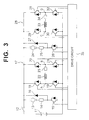
- a switch 12 is connected with a positive electrode of a battery 11, and an armature 13, an armature current detector 14 and an armature chopper element 15 for the first motor 6 are connected in series between the other end of the switch 12 and a negative electrode of the battery 11.
- a flywheel diode 16 is connected in parallel to the series circuit consisting of the armature 13 and the armature current detector 14.
- a field current control circuit section 17 for the first motor 6 is connected between the other end of the switch 12 and the negative electrode of the battery 11.
- the field current control circuit section 17 is designed such that a series circuit consisting of first and second field chopper elements 18 and 19 and a series circuit consisting of third and fourth field chopper elements 20 and 21 are connected in parallel to each other.
- a field winding 22 and a field current detector 23 for the first motor 6 are connected in series between a node A of the first and second field chopper elements 18 and 19 and a node B of the third and fourth field chopper elements 20 and 21.
- an armature 24, an armature current detector 25 and an armature chopper element 26 for the second motor 7 are connected in series between the other end of the switch 12 and the negative electrode of the battery 11.
- a flywheel diode 27 is connected in parallel to the series circuit consisting of the armature 24 and the armature current detector 25.
- a field current control circuit section 28 for the second motor 7 is connected between the other end of the switch 12 and the negative electrode of the battery 11.
- the field current control circuit section 28 is designed such that a series circuit consisting of first and second field chopper elements 29 and 30 and a series circuit consisting of third and fourth field chopper elements 31 and 32 are connected in parallel to each other.
- a field winding 33 and a field current detector 34 for the second motor 7 are connected in series between a node C of the first and second field chopper elements 29 and 30 and a node D of the third and fourth field chopper elements 31 and 32.
- the respective gate terminals of the armature chopper element 15 and the first to fourth field chopper elements 18 to 21 of the field current control circuit section 17 for the first motor 6, and the armature chopper element 26 and the first to fourth field chopper elements 29 to 32 of the field current control circuit section 28 for the second motor 7 are connected to a drive circuit 35, respectively.
- the drive circuit 35 controls the armature current and the field current for the first motor 6 by turning on/off the armature chopper element 15 and the first to fourth field chopper elements 18 to 21, and also controls the armature current and the field current for the second motor 7 by turning on/off the armature chopper element 26 and the first to fourth field chopper elements 29 to 32.
- the conventional vehicle control apparatus has a circuit structure in which a control circuit for controlling the drive of the first motor 6 and a control circuit for controlling the drive of the second motor 7 are connected in parallel to each other, there arises such a problem that the number of elements that constitutes the control apparatus, in particular, the number of elements for controlling a large current are large, and the entire vehicle control apparatus increases in size.
- the present invention has been made in order to eliminate the above problems, and therefore an object of the present invention is to provide a downsized vehicle control apparatus which is capable of controlling two DC separately excited motors.
- a vehicle control apparatus for a vehicle which is driven using first and second DC separately excited motors, comprising: a battery; a first field current control circuit section connected between both ends of the battery and having a plurality of field chopper elements connected to the field winding of a first motor and a first field current detector connected in series to the field winding of the first motor; a second field current control circuit section connected between both ends of the battery and having a plurality of field chopper elements connected to the field winding of a second motor and a second field current detector connected in series to the field winding of the second motor; an armature current control circuit section having an armature for the first motor, an armature for the second motor, an armature current detector, a first armature chopper element for controlling the drive of the motors which is common to the first and second motors, and a second armature chopper element for controlling regenerative braking which is connected in parallel to the series circuit consisting of
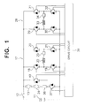
- a vehicle control apparatus is directed to an apparatus for controlling the drive of first and second DC separately excited motors 6 and 7 which are coupled to right and left front wheels 1 and 2 through transmissions 4 and 5, respectively, as in a three-wheel folk lift shown in Fig. 2.
- One end of a switch 12 is connected with a positive electrode of a battery 11, and an armature 13 for a first motor 6, an armature 24 for a second motor 7, an armature current detector 36 and an armature chopper element 37 are connected in series between the other end of the switch 12 and a negative electrode of the battery 11.
- An armature chopper element 40 for controlling regenerative braking is connected in parallel to the series circuit consisting of the armatures 13, 24 and the armature current detector 36.
- the armature current detector 36, the armature chopper elements 37 and 40 are members common to the first motor 6 and the second motor 7, respectively.
- a field current control circuit section 17 for the first motor 6 is connected between the other end of the switch 12 and the negative electrode of the battery 11.
- the field current control circuit section 17 is designed such that a series circuit consisting of first and second field chopper elements 18 and 19 and a series circuit consisting of third and fourth field chopper elements 20 and 21 are connected in parallel to each other.
- a field winding 22 and a field current detector 23 for the first motor 6 are connected in series between a node A of the first and second field chopper elements 18 and 19 and a node B of the third and fourth field chopper elements 20 and 21.
- a field current control circuit section 28 for the second motor 7 is connected in series between the other end of the switch 12 and the negative electrode of the battery 11.
- the field current control circuit section 28 is designed such that a series circuit consisting of first and second field chopper elements 29 and 30 and a series circuit consisting of third and fourth field chopper elements 31 and 32 are connected in parallel to each other.
- a field winding 33 and a field current detector 34 for the second motor 7 are connected in series between a node C of the first and second field chopper elements 29 and 30 and a node D of the third and fourth field chopper elements 31 and 32.
- a drive circuit 39 is connected to the respective gate terminals of the common chopper elements 37 and 40, and the respective field chopper elements 18 to 21 and 29 to 32 of the field current control circuit sections 17 and 28.
- the control apparatus is designed in such a manner that the armature 13 of the first motor 6 and the armature 24 of the second motor 7 are connected in series to each other, and the common armature current detector 36, armature chopper elements 37 and 40 are connected to those armatures 13 and 24, instead of the conventional vehicle control apparatus shown in Fig. 3 in which the armature current detector 14, armature chopper element 15 and flywheel diode 16 for controlling the armature 13 of the first motor 6, and the armature current detector 25, armature chopper element 26 and flywheel diode 27 for controlling the armature 24 of the second motor 7 are provided individually from each other.
- an applied voltage across and a current flowing in the armature 13 of the first motor 6 and the armature 24 of the second motor 7 are controlled by turning on/off the common armature chopper element 37.
- the armature chopper element 37 When the armature chopper element 37 is on, a current flows into the battery 11 from the battery 11 through the armatures 13 and 24, the armature current detector 36 and the armature chopper element 37, whereas when the armature chopper element 37 is off, a current flows into the armatures 13 and 24 from the armatures 13 and 24 through the armature current detector 36 and the armature chopper element 40.
- a field developed by the field winding 22 of the first motor 6 and the field winding 33 of the second motor 7 is controlled by turning on/off the first to fourth field chopper elements 18 to 21 within the field current control circuit section 17 and the first to fourth field chopper elements 29 to 32 within the field current control circuit section 28.
- the first chopper element 18 within the field current control circuit section 17 is turned on, and the fourth field chopper element 21 is then turned on/off.
- the fourth field chopper element 21 When the fourth field chopper element 21 is on, a current flows into the battery 11 from the battery 11 through the first field chopper element 18, the field winding 22, the field current detector 23 and the fourth field chopper element 21. When the fourth field chopper element 21 is turned off, a current flows into the fielding winding 22 from the field winding 22 through the field current detector 23, the third field chopper element 20 and the first field chopper element 18 due to an inductance energy of the field winding 22.
- the drive circuit 39 inputs detection signals from the armature current detector 36, and the field current detectors 23 and 34, respectively, to turn on/off the common armature chopper element 37 and the respective field chopper elements 18 to 21 and 29 to 32 within the field current control circuit sections 17 and 28, thereby controlling the armature current and the field current for the first motor 6 so that the first motor 6 is driven by the desired rotational frequency or torque, and also controlling the armature current and the field current for the second motor 7 so that the second motor 7 is driven by a desired rotational frequency or torque.
- n1 (1/2 ⁇ ) ⁇ (Va1 - Vbu1 - Ia1 ⁇ Ra1) / K ⁇ 1 ⁇ ⁇ 60 where K ⁇ 1 is a function of the field current If1.
- n2 (1/2 ⁇ ) ⁇ (Va2 - Vbu2 - Ia2 ⁇ Ra2) / K ⁇ 2 ⁇ ⁇ 60 where K ⁇ 2 is a function of the field current If2.
- the rotational frequencies n1 and n2 of both the motors 6 and 7 can be set at desired values, respectively, on the basis of the above expressions (1) and (2).
- the rotational frequencies n1 and n2 of both the motors 6 and 7 may be set so as to form the ratio of the rotational frequencies according to the turning radius.
- the field current of the motor coupled to the inner wheel is set at 0 so that the torque of the motor becomes 0.
- the field chopper elements 18 to 21 within the field current control circuit section 17 are controlled so that the field current If1 becomes 0 when the vehicle is turned counterclockwise, the torque of the first motor 6 coupled to the left front wheel 1 becomes 0, and the turn radius is obtained in response to this torque.
- the inner wheel is reversely rotated so that the turning radius can be further reduced.
- the drive circuit 39 controls the armature chopper element 37 on the basis of the armature currents of the armatures 13 and 24 which are detected by the armature current detector 36.
- the apparatus can be structured that voltages applied across the respective armatures 13 and 24 are detected by a voltage detector not shown so that armature chopper element 37 is controlled on the basis of the detected voltages.
- the field chopper elements 18 to 21 and 29 to 32 are controlled by the drive circuit 39 to increase the field currents If1 and If2 of the field windings 22 and 33, thus turning off the armature chopper element 37, and also the armature chopper element 40 for controlling regenerative braking is turned on/off to control currents flowing in the armatures 13 and 24, thereby being capable of controlling the regenerative braking.
- the vehicle control apparatus since the vehicle control apparatus according to the present invention is structured in such a manner that the armatures of the first and second motors are controlled by the common armature chopper element, the number of elements that structures the apparatus is reduced, and the downsizing of the vehicle control apparatus is achieved.
- the armature chopper element for controlling regenerative braking connected in parallel to the series circuit consisting of the armature of the first motor and the armature of the second motor is turned on/off by the drive circuit, the regenerative braking can be controlled.
- the present invention provides a downsized vehicle control apparatus which is capable of controlling two DC separately excited motors.
- An armature of a first motor, an armature of a second motor and an armature chopper element for controlling the drive of the motors which is common to both of those motors are connected in series between the ends of a battery, and a drive circuit turns on/off the common armature chopper element for controlling the drive of the motors and a plurality of field chopper elements for the respective first and second motors to control the armature currents and the field currents in the first and second motors, respectively, thereby driving both of the motors with the desired rotational frequency or torque.
- the drive circuit controls the on/off operation of an armature chopper element for controlling regenerative braking which is connected in parallel to the series circuit consisting of the armature of the first motor and the armature of the second motor at the time of the regenerative braking to control a current flowing in the armatures of the first and second motors.
Landscapes
- Engineering & Computer Science (AREA)
- Life Sciences & Earth Sciences (AREA)
- Sustainable Development (AREA)
- Sustainable Energy (AREA)
- Power Engineering (AREA)
- Transportation (AREA)
- Mechanical Engineering (AREA)
- Electric Propulsion And Braking For Vehicles (AREA)
- Control Of Multiple Motors (AREA)
Applications Claiming Priority (3)
| Application Number | Priority Date | Filing Date | Title |
|---|---|---|---|
| JP9296919A JPH11136811A (ja) | 1997-10-29 | 1997-10-29 | 車両制御装置 |
| JP296919/97 | 1997-10-29 | ||
| JP29691997 | 1997-10-29 |
Publications (2)
| Publication Number | Publication Date |
|---|---|
| EP0913291A2 true EP0913291A2 (de) | 1999-05-06 |
| EP0913291A3 EP0913291A3 (de) | 2001-08-29 |
Family
ID=17839881
Family Applications (1)
| Application Number | Title | Priority Date | Filing Date |
|---|---|---|---|
| EP98119025A Withdrawn EP0913291A3 (de) | 1997-10-29 | 1998-10-08 | Fahrzeugregelvorrichtung |
Country Status (3)
| Country | Link |
|---|---|
| US (1) | US6028403A (de) |
| EP (1) | EP0913291A3 (de) |
| JP (1) | JPH11136811A (de) |
Cited By (1)
| Publication number | Priority date | Publication date | Assignee | Title |
|---|---|---|---|---|
| WO2020135688A1 (zh) * | 2018-12-29 | 2020-07-02 | 上海理工大学 | 他励直流电机驱动装置及设备 |
Families Citing this family (25)
| Publication number | Priority date | Publication date | Assignee | Title |
|---|---|---|---|---|
| US6757597B2 (en) * | 2001-01-31 | 2004-06-29 | Oshkosh Truck | A/C bus assembly for electronic traction vehicle |
| US7729831B2 (en) * | 1999-07-30 | 2010-06-01 | Oshkosh Corporation | Concrete placement vehicle control system and method |
| US6611116B2 (en) * | 2000-05-10 | 2003-08-26 | Curtis Instruments, Inc. | Anti-spin control for a separately excited motor drive system |
| JP3884909B2 (ja) * | 2000-12-06 | 2007-02-21 | 株式会社日立製作所 | 電気車及びその制御装置 |
| US7277782B2 (en) * | 2001-01-31 | 2007-10-02 | Oshkosh Truck Corporation | Control system and method for electric vehicle |
| US7379797B2 (en) * | 2001-01-31 | 2008-05-27 | Oshkosh Truck Corporation | System and method for braking in an electric vehicle |
| US7254468B2 (en) * | 2001-12-21 | 2007-08-07 | Oshkosh Truck Corporation | Multi-network control system for a vehicle |
| US7302320B2 (en) | 2001-12-21 | 2007-11-27 | Oshkosh Truck Corporation | Failure mode operation for an electric vehicle |
| US7520354B2 (en) * | 2002-05-02 | 2009-04-21 | Oshkosh Truck Corporation | Hybrid vehicle with combustion engine/electric motor drive |
| US7439711B2 (en) * | 2004-09-27 | 2008-10-21 | Oshkosh Corporation | Energy storage device including a status indicator |
| US7937194B2 (en) * | 2004-09-27 | 2011-05-03 | Oshkosh Corporation | System and method for reducing wheel slip and wheel locking in an electric vehicle |
| US7208894B1 (en) | 2005-11-01 | 2007-04-24 | Earle John L | Electric vehicle motor and control system with high efficiency regeneration |
| US8139109B2 (en) | 2006-06-19 | 2012-03-20 | Oshkosh Corporation | Vision system for an autonomous vehicle |
| US8947531B2 (en) | 2006-06-19 | 2015-02-03 | Oshkosh Corporation | Vehicle diagnostics based on information communicated between vehicles |
| US8337352B2 (en) | 2010-06-22 | 2012-12-25 | Oshkosh Corporation | Electromechanical variable transmission |
| US9114804B1 (en) | 2013-03-14 | 2015-08-25 | Oshkosh Defense, Llc | Vehicle drive and method with electromechanical variable transmission |
| US9650032B2 (en) | 2015-02-17 | 2017-05-16 | Oshkosh Corporation | Multi-mode electromechanical variable transmission |
| US12078231B2 (en) | 2015-02-17 | 2024-09-03 | Oshkosh Corporation | Inline electromechanical variable transmission system |
| US10584775B2 (en) | 2015-02-17 | 2020-03-10 | Oshkosh Corporation | Inline electromechanical variable transmission system |
| US10421350B2 (en) | 2015-10-20 | 2019-09-24 | Oshkosh Corporation | Inline electromechanical variable transmission system |
| US10982736B2 (en) | 2015-02-17 | 2021-04-20 | Oshkosh Corporation | Multi-mode electromechanical variable transmission |
| US10578195B2 (en) | 2015-02-17 | 2020-03-03 | Oshkosh Corporation | Inline electromechanical variable transmission system |
| US9651120B2 (en) | 2015-02-17 | 2017-05-16 | Oshkosh Corporation | Multi-mode electromechanical variable transmission |
| US9656659B2 (en) | 2015-02-17 | 2017-05-23 | Oshkosh Corporation | Multi-mode electromechanical variable transmission |
| US11701959B2 (en) | 2015-02-17 | 2023-07-18 | Oshkosh Corporation | Inline electromechanical variable transmission system |
Family Cites Families (7)
| Publication number | Priority date | Publication date | Assignee | Title |
|---|---|---|---|---|
| FR2194347A5 (de) * | 1972-07-31 | 1974-02-22 | Jeumont Schneider | |
| JPS5416006B2 (de) * | 1973-01-29 | 1979-06-19 | ||
| US4355267A (en) * | 1981-04-29 | 1982-10-19 | Westinghouse Electric Corp. | Propulsion motor control apparatus |
| US4453111A (en) * | 1982-04-09 | 1984-06-05 | Westinghouse Electric Corp. | Electric drive for submarines |
| US4500818A (en) * | 1983-12-22 | 1985-02-19 | General Electric Company | Dual motor proportioning control |
| US5070283A (en) * | 1990-05-07 | 1991-12-03 | Raymond | Traction motor controller for forklift vehicles |
| US5332954A (en) * | 1992-03-30 | 1994-07-26 | Solaria Research Enterprises Ltd. | Optimal DC motor/controller configuration |
-
1997
- 1997-10-29 JP JP9296919A patent/JPH11136811A/ja active Pending
-
1998
- 1998-10-08 EP EP98119025A patent/EP0913291A3/de not_active Withdrawn
- 1998-10-13 US US09/170,928 patent/US6028403A/en not_active Expired - Fee Related
Cited By (2)
| Publication number | Priority date | Publication date | Assignee | Title |
|---|---|---|---|---|
| WO2020135688A1 (zh) * | 2018-12-29 | 2020-07-02 | 上海理工大学 | 他励直流电机驱动装置及设备 |
| US11239775B1 (en) | 2018-12-29 | 2022-02-01 | University Of Shanghai For Science And Technology | Separately excited direct current motor drive apparatus and equipment |
Also Published As
| Publication number | Publication date |
|---|---|
| JPH11136811A (ja) | 1999-05-21 |
| US6028403A (en) | 2000-02-22 |
| EP0913291A3 (de) | 2001-08-29 |
Similar Documents
| Publication | Publication Date | Title |
|---|---|---|
| EP0913291A2 (de) | Fahrzeugregelvorrichtung | |
| EP2812992B1 (de) | Rekonfigurierbare batterie | |
| US20120133310A1 (en) | Reconfigurable battery | |
| JP2006109612A (ja) | 車両用の電源装置 | |
| US5598072A (en) | Regenerative braking circuit utilizing separately excited motor | |
| US5661379A (en) | Electric motor | |
| JP2000069613A (ja) | バッテリ車両の走行モータ制御装置 | |
| JP3180300B2 (ja) | 電気自動車の駆動システム | |
| JPS6259559B2 (de) | ||
| Tanaka | Motors for electric power steering | |
| JPH0930481A (ja) | 補助動力付き自転車 | |
| JP3227621B2 (ja) | 電動産業車両の走行制御装置 | |
| JPH09117173A (ja) | 直流モータ駆動装置 | |
| JPH0610404Y2 (ja) | 電気車の自動操舵装置 | |
| JP3332045B2 (ja) | 電流制御回路 | |
| JPH06233409A (ja) | 電動車両のモータ制御装置 | |
| US20260054584A1 (en) | Electrified vehicle | |
| JP3345915B2 (ja) | バッテリ車の走行制御装置 | |
| JP3063787B2 (ja) | 電動車両制御装置 | |
| US20260058572A1 (en) | Electrified vehicle | |
| JPS5827730B2 (ja) | 電気車制御装置 | |
| JPH10310398A (ja) | バッテリー車両の回生制動装置 | |
| JPH0811536B2 (ja) | モータ駆動用電流制御装置 | |
| JP2000134971A (ja) | 電動車椅子の制御方法 | |
| JPH0614406A (ja) | 電気自動車の電気システム |
Legal Events
| Date | Code | Title | Description |
|---|---|---|---|
| PUAI | Public reference made under article 153(3) epc to a published international application that has entered the european phase |
Free format text: ORIGINAL CODE: 0009012 |
|
| AK | Designated contracting states |
Kind code of ref document: A2 Designated state(s): AT BE CH CY DE DK ES FI FR GB GR IE IT LI LU MC NL PT SE |
|
| AX | Request for extension of the european patent |
Free format text: AL;LT;LV;MK;RO;SI |
|
| PUAL | Search report despatched |
Free format text: ORIGINAL CODE: 0009013 |
|
| AK | Designated contracting states |
Kind code of ref document: A3 Designated state(s): AT BE CH CY DE DK ES FI FR GB GR IE IT LI LU MC NL PT SE |
|
| AX | Request for extension of the european patent |
Free format text: AL;LT;LV;MK;RO;SI |
|
| 17P | Request for examination filed |
Effective date: 20010808 |
|
| RAP1 | Party data changed (applicant data changed or rights of an application transferred) |
Owner name: KABUSHIKI KAISHA TOYOTA JIDOSHOKKI |
|
| AKX | Designation fees paid |
Free format text: DE FR GB |
|
| STAA | Information on the status of an ep patent application or granted ep patent |
Free format text: STATUS: THE APPLICATION HAS BEEN WITHDRAWN |
|
| 18W | Application withdrawn |
Effective date: 20060223 |