EP0913280A1 - Ressort d'essieu hydropneumatique pour essieux de véhicules entraínés - Google Patents
Ressort d'essieu hydropneumatique pour essieux de véhicules entraínés Download PDFInfo
- Publication number
- EP0913280A1 EP0913280A1 EP98119511A EP98119511A EP0913280A1 EP 0913280 A1 EP0913280 A1 EP 0913280A1 EP 98119511 A EP98119511 A EP 98119511A EP 98119511 A EP98119511 A EP 98119511A EP 0913280 A1 EP0913280 A1 EP 0913280A1
- Authority
- EP
- European Patent Office
- Prior art keywords
- axle
- pressure
- suspension system
- axle suspension
- hydraulic
- Prior art date
- Legal status (The legal status is an assumption and is not a legal conclusion. Google has not performed a legal analysis and makes no representation as to the accuracy of the status listed.)
- Granted
Links
- 239000000725 suspension Substances 0.000 claims description 71
- 239000012530 fluid Substances 0.000 claims description 7
- 238000013016 damping Methods 0.000 claims description 5
- 238000013461 design Methods 0.000 claims description 2
- 230000005484 gravity Effects 0.000 claims description 2
- 238000000034 method Methods 0.000 claims description 2
- 238000001514 detection method Methods 0.000 claims 1
- 230000001105 regulatory effect Effects 0.000 claims 1
- 238000011068 loading method Methods 0.000 abstract 2
- 230000036316 preload Effects 0.000 description 5
- IJGRMHOSHXDMSA-UHFFFAOYSA-N Atomic nitrogen Chemical compound N#N IJGRMHOSHXDMSA-UHFFFAOYSA-N 0.000 description 2
- 230000001419 dependent effect Effects 0.000 description 2
- 238000011161 development Methods 0.000 description 2
- 230000018109 developmental process Effects 0.000 description 2
- 229910001873 dinitrogen Inorganic materials 0.000 description 2
- 239000007789 gas Substances 0.000 description 2
- 230000010355 oscillation Effects 0.000 description 2
- 102100039385 Histone deacetylase 11 Human genes 0.000 description 1
- 108700038332 Histone deacetylase 11 Proteins 0.000 description 1
- 230000000903 blocking effect Effects 0.000 description 1
- 238000009530 blood pressure measurement Methods 0.000 description 1
- 230000001447 compensatory effect Effects 0.000 description 1
- 238000010586 diagram Methods 0.000 description 1
- 230000000694 effects Effects 0.000 description 1
- 238000007654 immersion Methods 0.000 description 1
- 238000012423 maintenance Methods 0.000 description 1
- 238000012986 modification Methods 0.000 description 1
- 230000004048 modification Effects 0.000 description 1
- 230000003287 optical effect Effects 0.000 description 1
- 230000000750 progressive effect Effects 0.000 description 1
- 230000000384 rearing effect Effects 0.000 description 1
- 230000000284 resting effect Effects 0.000 description 1
- 239000002689 soil Substances 0.000 description 1
- 230000003068 static effect Effects 0.000 description 1
- 238000003971 tillage Methods 0.000 description 1
- 238000012549 training Methods 0.000 description 1
- 238000012546 transfer Methods 0.000 description 1
Images

Classifications
-
- B—PERFORMING OPERATIONS; TRANSPORTING
- B60—VEHICLES IN GENERAL
- B60G—VEHICLE SUSPENSION ARRANGEMENTS
- B60G21/00—Interconnection systems for two or more resiliently-suspended wheels, e.g. for stabilising a vehicle body with respect to acceleration, deceleration or centrifugal forces
- B60G21/02—Interconnection systems for two or more resiliently-suspended wheels, e.g. for stabilising a vehicle body with respect to acceleration, deceleration or centrifugal forces permanently interconnected
- B60G21/06—Interconnection systems for two or more resiliently-suspended wheels, e.g. for stabilising a vehicle body with respect to acceleration, deceleration or centrifugal forces permanently interconnected fluid
- B60G21/073—Interconnection systems for two or more resiliently-suspended wheels, e.g. for stabilising a vehicle body with respect to acceleration, deceleration or centrifugal forces permanently interconnected fluid between wheels on the same axle but on different sides of the vehicle, i.e. the left and right wheel suspensions being interconnected
-
- B—PERFORMING OPERATIONS; TRANSPORTING
- B60—VEHICLES IN GENERAL
- B60G—VEHICLE SUSPENSION ARRANGEMENTS
- B60G17/00—Resilient suspensions having means for adjusting the spring or vibration-damper characteristics, for regulating the distance between a supporting surface and a sprung part of vehicle or for locking suspension during use to meet varying vehicular or surface conditions, e.g. due to speed or load
- B60G17/02—Spring characteristics, e.g. mechanical springs and mechanical adjusting means
- B60G17/04—Spring characteristics, e.g. mechanical springs and mechanical adjusting means fluid spring characteristics
- B60G17/0416—Spring characteristics, e.g. mechanical springs and mechanical adjusting means fluid spring characteristics regulated by varying the resiliency of hydropneumatic suspensions
-
- B—PERFORMING OPERATIONS; TRANSPORTING
- B60—VEHICLES IN GENERAL
- B60G—VEHICLE SUSPENSION ARRANGEMENTS
- B60G9/00—Resilient suspensions of a rigid axle or axle housing for two or more wheels
- B60G9/003—Resilient suspensions of a rigid axle or axle housing for two or more wheels the axle being rigidly connected to a trailing guiding device
-
- B—PERFORMING OPERATIONS; TRANSPORTING
- B60—VEHICLES IN GENERAL
- B60G—VEHICLE SUSPENSION ARRANGEMENTS
- B60G2500/00—Indexing codes relating to the regulated action or device
- B60G2500/02—Supply or exhaust flow rates; Pump operation
Definitions
- the invention relates to a hydropneumatic front axle suspension system for the driven axle of an agricultural Work vehicle, especially for the front axle an agricultural tractor, with at least one between vehicle body hydraulic cylinders arranged on the axle beam, whose annulus and its pressure chamber each with at least one Pressure fluid accumulator are connected, and with a through a hydraulic pump fed valve device for level control, which depend on the pressure of the pressure medium accumulator the load on the axle beam.
- the front axle of agricultural work vehicles be suspended from the vehicle body.
- the suspension system is locked mechanically or hydraulically (Peter Pickel et. Al. "What are the chances of spring loaded Tractors "in the German magazine” Landtechnik "10/90, Pages 363 - 366).
- the suspension is blocked. a. than required viewed to affect the control behavior of a Avoid power lift (DE-A-38 34 693). Especially when Plowing the front axle suspension is considered a hindrance (DE-C-42 42 448), so that a manually initiated shutdown the suspension is proposed.
- front cultivator or front packer suspension is considered disruptive because a particularly precise device management is important. It will therefore proposed the suspension via a push button block (brochure from Fendt: "Farmer”, HD11 / 95/15, page 14).
- a control unit has also been proposed (DE-A-43 08 460), that the operator has a choice between one manual or automatic lock of the suspension there, the automatic lock depending on certain Criteria, e.g. B. front loader work or work with the plow, he follows.
- EP-A-0 670 230 provides a pressure medium supply for a hydropneumatic, level-controlled axle suspension of a Work vehicle became known.
- This contains one of one Hydraulic pump fed hydraulic system, to the pressure accumulator and related to them above and below of a piston lying cylinder spaces of actuating cylinders Axle suspension are connected. If one falls below setting the desired level of pressure required the upper cylinder chamber through the hydraulic pump via the Hydraulic system filled up.
- To be different when used optionally Pump systems to maintain the pressure medium supply is the axle suspension when pressure medium is required Actuation of a consumer connected to the hydraulic pump arbitrarily simulated. For certain operations the suspension is switched off and the vehicle axle opposite the vehicle body blocked by the pressure in the upper The cylinder space is drained and the vehicle axle through the pressure in the second cylinder chamber against a stop is pressed on the vehicle body.
- Front axle Since the front axle suspension with high loads Front axle, such as those used in front loader work or when using a heavy front device, is always turned off, the mechanical and hydraulic spring components due to space and cost reasons designed a relatively low load, as in Road trip is given.
- the Pressure accumulator with a relatively small storage volume correspondingly steep course of the spring characteristic.
- the object underlying the invention is seen in a generic hydropneumatic axle suspension system for the driven axle of an agricultural work vehicle to train such that the driving characteristics of the Work vehicle to be further improved.
- the invention is based on the finding that maintenance the axle suspension, especially the hydropneumatic Front axle suspension in all load and driving conditions of the agricultural work vehicle is advantageous, which is contrary to previous assumptions.
- the axle suspension remains in particular with all front loader work all field and ground work and slow and fast Transport trips effective. Even if errors occur in Hydraulic or electrical components are supposed to be the suspension maintained and not contrary to previous practice not switched off become.
- the mechanical and hydropneumatic Components of the axle suspension system especially the hydraulic cylinders, the pressure medium accumulator, the valve device and the pressure supply, for a suspension under maximum Load on the axle beam designed.
- the maximum by the Axle load to be absorbed can be 70 kN, for example a tractor with a gross vehicle weight of 9000 kg and a permissible payload of 4000 kg.
- the valve device becomes such trained and controlled such that in the pressure medium stores, the pressure chamber and the annulus are always sufficient Pressure is maintained to under all load and Driving conditions of the vehicle a springs of the axle beam to allow, the spring rate depending on the respective Load on the axle beam.
- front axle suspension brings advantages in front loader and field work.
- the hydraulic cylinders are pre-tensioned by the pressure accumulators constantly loaded and push the wheels of the axle on the floor, so that this when driving over uneven floors not take off and the transfer of forces to the Soil is constantly guaranteed. Therefore the fuselage stops when driving over uneven ground, its position is more stable than with an unsprung vehicle. As a result, there are also fewer Compensatory movements by means of a hydraulic attachment position control required.
- the invention is preferred in the case of an oscillating, sprung axle suspension as applied by the still unpublished German patent application 196 43 263.4 was described and claimed by the applicant and on their Disclosure is hereby incorporated by reference.
- two hydraulic cylinders provided, the pressure rooms are above and whose piston rods are connected to the axle beam.
- the Pressure rooms are one below the other and with one or more pressure chamber pressure accumulators connected in parallel.
- the annular spaces are located one below the other and with one or more parallel connected ring pressure accumulators directly in Connection.
- the valve device preferably contains at least one Electromagnetically controllable on the one hand with a hydraulic pump and a storage container and on the other hand with the Annulus and pressure control related level control valve, which due to being detected by a position sensor Deviations from a central level position via a control unit is controllable.
- the level control valve and the annulus and between the level control valve and the Pressure space of the at least one hydraulic cylinder is one each Unlockable check valve arranged, which against a Backflow of pressure medium from the annular space or the pressure space locks.
- a valve device suitable for the present invention is in DE 42 42 448, the disclosure of which is hereby incorporated by reference is described in detail. Unlike that known valve arrangement is omitted in the present suspension system according to the invention between the pressure chamber and the associated pressure medium accumulator check valve, which can be closed manually or automatically.
- the total nominal volume of the pressure chamber or pressure accumulators is preferably at least twice the total nominal volume the or the annulus.
- the pressure medium accumulator is, for example Nitrogen gas pressure accumulator. You must have large enough volume have the desired under all load conditions To be able to maintain axle suspension. In particular, should can be avoided that already with a soft suspension relatively low axle loads, the axle beam attached to the vehicle body creates or strikes against this.
- the pressure fluid accumulators have a progressive spring characteristic.
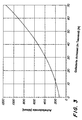
- the slope of the spring characteristic curves (dependence of the axle spring rate on the axle load) of pressure medium accumulators with a large volume is less than that of pressure medium accumulators with a smaller volume. It is particularly advantageous to use pressure medium accumulators with a relatively small slope of the spring characteristic, so that the slope of the spring characteristic of the axle suspension with low front axle loads of, for example, 10 kN in the range between 0.003 N / mm / N and 0.01 N / mm / N.
- the slope of the spring characteristic is between 0.015 N / mm / N and 0.035 N / mm / N , preferably about 0.025 N / mm / N.
- the axle spring rate is given in Newtons per millimeter of travel in relation to the axle load.
- the spring rate for a front axle load of, for example, 10 kN at 100 to 250 N / mm, preferably at 180 N / mm, (relatively soft spring) and at an axle load of 70 kN at 1000 to 1300 N / mm, preferably 1150 N / mm, (relatively hard spring).
- the load range in the front loader operation is sufficiently rigid to keep the vehicle stable against pitching when the load is lifted.
- the spring rate should not be too low in the plowing load range either.
- the valve device advantageously contains one Pressure control, the pressure on the annulus side of the least a hydraulic cylinder on a middle one, essentially sets a constant value. This tightens the pressure the spring system on the annulus side and puts the Working area for the pressure chamber pressure accumulator. On the The weight force resting on the axle is under load on the pressure chamber side as well as the preload pressure on the annulus side. This enables to cover a large load range with the spring system, without the need for different spring preloads (see for example DE 41 38 208) must be switched. The preload on the annulus side protects the pressure chamber pressure accumulator before under or overload.
- valve device is designed to control the pressure on the pressure chamber side of the at least one hydraulic cylinder depending on a changing load on the axis Readjust the load.
- the load-dependent position of the Axis can be determined by signals from a position sensor, the a load-related change in distance between the axle beam and Vehicle body detected.
- the level setting or regulation is below active in all operating conditions and provides a specifiable average height of the vehicle body above the axle beam on.
- the level control makes the altitude independent maintain static load changes.
- the middle Altitude can be determined by a calibration procedure, in which the valve device is driven by the entire To travel through the stroke range of the hydraulic cylinders. From the End points (upper and lower stop) of the lifting movement then the average altitude is determined and saved.
- the valve device at least one electromagnetically controllable Level control valve, which can be refilled or Drain hydraulic fluid into the pressure chamber and / or Annulus serves.
- the level control valve is operated by an electrical Control circuit based on signals from a position sensor controlled.
- the position sensor signals become continuous first average values over time intervals of 2 to 10 seconds, preferably of about 6 sec.
- the specific time interval becomes dependent on the inertia of the entire control loop and the oscillation periods of the lowest natural frequency of the vehicle. There should be at least 5 Periods of oscillation. Control signals for refilling or draining hydraulic fluid will only be connected to the Level control valve issued when the first average one predeterminable tolerance range of a target value leaves.
- the tolerance range is, for example, within ⁇ 7.5% of the total Spring strokes (e.g. 100 mm) on both sides of the setpoint.
- the setpoint normally corresponds to the average spring stroke. This means that a level compensation is not already based on Natural vibrations of the vehicle, but only if the Load changed over long periods of time.
- the position sensor signals continuous second averages over time intervals from 0.3 to 2 sec, preferably about 0.8 sec.
- the second mean value is again within the tolerance range, that ends at least one level control valve the refill or drain.
- the time constant of the second mean is thus chosen that overshoot of the axis position over the setpoint is avoided. It depends in particular on the pump power and the volume of the hydraulic cylinders and the pressure medium accumulator from.
- a level control is inhibited to one for the operator unexpected behavior (pitch compensation) of the Avoid axle suspension. For example, when standing Vehicle whose load due to the attachment or removal of a device changes, the vehicle tilts. This should be in the state not be balanced.
- the level control can by Closing the valves of the valve device are blocked. However, the suspension remains effective because of the hydraulic connections between the pressure rooms and the pressure room pressure accumulator and between the annuli and the annulus pressure accumulator remain open so that fluid exchange can take place.
- a advantageous embodiment of the invention therefore provides between the pressure chambers of the hydraulic cylinders and the associated Pressure medium accumulator an adjustable proportional valve to arrange, by which the damping rate of the spring system adjust or regulate.
- the misconduct of the vehicle can be determined from the amplitudes and frequencies of the position sensor signal read off. Leave high amplitudes and low frequencies conclude that the tractor has relatively soft suspension. By narrowing the passage in the proportional valve the spring stiffness can be increased. It is also possible, Corresponding conclusions from pressure measurements on the pressure medium accumulator or to win the pressure chambers of the hydraulic cylinders.
- the axle suspension system according to the invention is particularly suitable for a driven, oscillating, rigid front axle, on which the vehicle body is roughly symmetrical over two arranged on both sides of the pendulum axis, essentially vertical aligned hydraulic cylinder supports.
- the horizontal forces in the longitudinal direction of the vehicle are particularly advantageous intercept by a pull or push link, which is rigidly attached to the rigid axle and via a joint the vehicle body is articulated.
- the joint is preferred a ball joint.
- the push rod should be as long as possible.
- the thrust link has a Has length that is greater than the effective tire diameter the front wheels, for example 800 mm.
- the length of the pull or push link is preferably dimensioned so that the braking torque goes as far as possible through the suspension, at least 50%, is compensated. If it is too short Pull or push control arms overcompensate the braking torque and the vehicle rears up. This is considered to be disadvantageous. Rather, the vehicle should accelerate and If possible, keep the brakes in their horizontal position. This is then the case when compensation between braking effect (Immersion) and change in tractive force (rearing). At too short a pull or push link can be load-related Restoring torques occur, which lead to undesirable fluctuations in tractive force cause the vehicle is not quiet remains.
- the handlebar length can preferably 40% of the Center distance.
- the pull or push link is preferred designed so that it in the vehicle longitudinal direction extending drive axle at least partially covers and protects against dirt and damage.
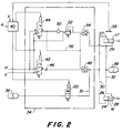
- Fig. 1 is a partial section of the vehicle body forming frame 10, the front axle body 12 and a front wheel 14 of a tractor not shown schematically indicated.
- the front axle body 12 contains a middle one Pendulum axis, which is not shown in Fig. 1, however. Details on this can be found on October 19, 1996, unpublished German patent application 196 43 263.4 of the applicant.
- Hydraulic cylinders 16, 17 substantially symmetrical to Pendulum axis arranged, one of which is visible in Fig. 1.
- the hydraulic cylinders 16, 17 are each with one end articulated on the frame 10 and with the other end hinged to the front axle body 12.
- the hydraulic cylinders 16, 17 are in front of the center line of the front axle beam 12 hinged to this.
- the front axle body 12 is supported by a pull or Push arm 20 in the vehicle longitudinal direction from the frame 10.
- the front end of the thrust link 20 is rigid on the front axle body 12 attached. Its rear end protrudes above Ball joint 22 in connection with the frame 10.
- the ball joint 22 allows the front axle body 12 up and down swing out. Lateral movement of the front axle beam 12 is limited by a Panhard rod, not shown. It does not run within the thrust link 20 Shown drive shaft for the front axle.
- the The length of the push tube is about 1000 mm and the Articulation points of the hydraulic cylinders 16, 17 on the front axle body 12 can be in about 200 mm from the center line of the Front axle body 12 lie.
- the hydraulic cylinders 16, 17 each have a cylinder housing, in which a piston 24 is guided in a longitudinally displaceable manner.
- the piston 24 divides the cylinder housing into an upper pressure chamber 26, 27 and a lower annular space 28, 29.
- the pressure spaces 26, 27 and the annular spaces 28, 29 of the two hydraulic cylinders 16, 17 are via hydraulic lines 30, 32 with a valve device 34, with two pressure chamber pressure accumulators 36, 36a and one Annulus storage 38 in connection.
- the pressure accumulators 36, 36a and 38 are nitrogen gas pressure accumulators known design.
- the pressure chambers 26, 27 of the two hydraulic cylinders 16, 17 are with each other via hydraulic line 30 and another Hydraulic line 31 with the two pressure chamber pressure accumulators 36, 36a, of which only one is shown in FIG. 2, connected.
- the annular spaces 28, 29 of the two hydraulic cylinders 16, 17 are with each other and with the hydraulic line 32 Annulus pressure accumulator 38 connected.
- the connections between the pressure chambers 26, 27 and the pressure chamber pressure accumulators 36, 36a and between the annular spaces 28, 29 and the annular space pressure accumulator 38 will not be complete under any operating conditions locked so that the suspension is always effective.
- the valve device 34 can consist of one component, in which several valves are formed, some of which are by an electrical or electronic control unit 40 are controllable.
- the valve device 34 contains a first and a second Solenoid valve 42, 44 with two positions and three each Hydraulic connections.
- a first hydraulic connection is on a hydraulic pump P, not shown, and one each second hydraulic connection is not closer to one shown hydraulic collection container S connected.
- Of the third hydraulic connection of the first hydraulic valve 42 is via a throttle point 46 and a first unlockable Check valve 48 with the hydraulic line 30 and Pressure rooms 26, 27 in connection.
- the third hydraulic connection of the second hydraulic valve 44 is above a check valve 50, a pressure control valve 52 and a second unlockable Check valve 54 with the hydraulic line 32 and Annuli 28, 29 in connection.
- the two unlockable check valves 48, 54 via control lines 56 from the third hydraulic connection of the second control valve 44 pending pressure controlled.
- the control unit 40 does not receive signals A one shown manually operable input unit, by the control unit 40 program and parameters of the Have the front axle suspension system adjusted and signals V a vehicle speed sensor, not shown.
- a Position sensor 58 detects the height of the vehicle body 10 via the front axle body 12 and indicates corresponding position signals the control unit 40.
- the control unit 40 forms from the Position sensor signals continuously mean values. Exceeding or falling below the mean values are around a medium altitude extending predeterminable position tolerance range, then a Leveling.
- control unit 40 electrical signals to the two as level control valves acting solenoid valves 42, 44 to remove them if necessary the shown rest position (solenoid valves are de-energized), in which the third hydraulic connection with the Collection container is connected in an excited position bring in which the third hydraulic connection with the Hydraulic pump is connected.
- the vehicle speed drops below a predeterminable value, control is omitted the solenoid valves 42, 44 so that they remain closed and there is no level control.
- the control unit 40 initiates a curtailment in which the first solenoid valve 42 in the illustrated de-energized Position remains and the second solenoid valve 44 is energized and its third hydraulic connection with the hydraulic pump P connects.
- the increasing pressure in the control lines 56 opens the unlockable check valves 48, 54 and that Pressure control valve 52 sets a predetermined pressure in the Hydraulic line 32 and the annular spaces 28, 29 a.
- the pressure in the pressure chambers 26, 27 and the associated pressure accumulator 36 is via the check valve 48 and the solenoid valve 42 to Collection container dismantled until the middle level is reported by the position sensor 58.
- the third Hydraulic connection of the solenoid valve 44 with the collecting container S connected the control lines 56 are depressurized and the Check valves 48, 54 close, so that another Pressure medium outflow from the pressure chambers 26, 27 is prevented.
- the control unit 40 thus initiates an adjustment in which both Solenoid valves 42, 44 energized and their third Hydraulic connections are connected to the hydraulic pump P.
- the increasing pressure in the control lines 56 opens the unlockable check valves 48, 54 and the pressure control valve 52 sets a predetermined pressure in the hydraulic line 32 and the annular spaces 28, 29.
- the pressure in the pressure rooms 26, 27 and the associated pressure chamber pressure reservoir 36 is via the first solenoid valve 42 and the check valve 48 so long built up until the middle level by the position sensor 58 is reported.
- the third hydraulic connections of the Solenoid valves 42, 44 connected to the collection container S the Control lines 56 are depressurized and the check valves 48, 54 close, so that a further pressure medium flow to the Pressure rooms 26, 27 is prevented.
- a controllable by the control unit 40 Proportional valve 60 are inserted over which the Can regulate the damping of the front axle suspension.
- the spring rate is approximately 200 N / mm with an axle load of 12000 N (unloaded front axle) and with an axle load of 64000 N (front axle loaded with front weights and front loader) approx. 1000 N / mm.
- the slope of the spring characteristic curve shown is about 0.0075 N / mm / N and for large axle loads of 70000 N at about 0.024 N / mm / N for small axle loads of 10000 N.
- the spring characteristic curve therefore has a comparatively small slope. The slope can be further reduced by not keeping the pressure in the annulus constant, but varying it depending on the load.
Landscapes
- Engineering & Computer Science (AREA)
- Mechanical Engineering (AREA)
- Vehicle Body Suspensions (AREA)
Applications Claiming Priority (2)
| Application Number | Priority Date | Filing Date | Title |
|---|---|---|---|
| DE19748224A DE19748224B4 (de) | 1997-10-31 | 1997-10-31 | Hydropneumatische Achsfederung für angetriebene Fahrzeugachsen |
| DE19748224 | 1997-10-31 |
Publications (2)
| Publication Number | Publication Date |
|---|---|
| EP0913280A1 true EP0913280A1 (fr) | 1999-05-06 |
| EP0913280B1 EP0913280B1 (fr) | 2004-03-10 |
Family
ID=7847267
Family Applications (1)
| Application Number | Title | Priority Date | Filing Date |
|---|---|---|---|
| EP98119511A Revoked EP0913280B1 (fr) | 1997-10-31 | 1998-10-15 | Ressort d'essieu hydropneumatique pour essieux de véhicules entraínés |
Country Status (7)
| Country | Link |
|---|---|
| US (1) | US6145859A (fr) |
| EP (1) | EP0913280B1 (fr) |
| AR (1) | AR017539A1 (fr) |
| AT (1) | ATE261360T1 (fr) |
| BR (1) | BR9804380A (fr) |
| CA (1) | CA2249727C (fr) |
| DE (2) | DE19748224B4 (fr) |
Cited By (5)
| Publication number | Priority date | Publication date | Assignee | Title |
|---|---|---|---|---|
| WO2005042283A1 (fr) | 2003-10-31 | 2005-05-12 | Deere & Company | Systeme d'essieu de vehicule, tube coulissant, essieu de vehicule et vehicule |
| EP1360078B1 (fr) * | 2001-02-14 | 2007-04-11 | HYDAC Technology GmbH | Systeme de suspension, notamment pour machine-outil |
| EP1987970A2 (fr) | 2007-05-04 | 2008-11-05 | Deere & Company | Système de déplacement actif pour véhicule agricole ou industriel |
| EP2098389A1 (fr) * | 2008-03-05 | 2009-09-09 | Deere & Company | Agencement de ressort hydraulique |
| EP3441244A1 (fr) * | 2017-08-11 | 2019-02-13 | Vermeer Manufacturing Company | Véhicules autopropulsés avec commande de tangage |
Families Citing this family (41)
| Publication number | Priority date | Publication date | Assignee | Title |
|---|---|---|---|---|
| EP1018292B8 (fr) * | 1999-01-09 | 2005-06-29 | GKN Walterscheid GmbH | Dispositif de levage pour bras inférieurs d'accouplement de tracteur |
| US6311795B1 (en) * | 2000-05-02 | 2001-11-06 | Case Corporation | Work vehicle steering and suspension system |
| US6988599B2 (en) | 2000-12-07 | 2006-01-24 | Visteon Global Technologies, Inc. | Compressible fluid strut |
| DE60109417T2 (de) | 2000-12-07 | 2006-04-13 | Visteon Global Technologies, Inc., Dearborn | Aufhängungssystem für ein fahrzeug |
| DE10107631B4 (de) * | 2001-02-15 | 2007-04-05 | Carl Freudenberg Kg | Verfahren und Einrichtung zur Steuerung des Federungsverhaltens bei Fahrzeugen mit hydropneumatischen Federungseinrichtungen und stark veränderbaren Achslastverhältnissen |
| US6722994B2 (en) * | 2001-03-09 | 2004-04-20 | Deer & Co. | Suspended drive axle and agricultural tractor with same |
| DE10111551A1 (de) * | 2001-03-10 | 2002-09-12 | Bayerische Motoren Werke Ag | Aktives Fahrwerksystem eines Fahrzeugs |
| US6578855B2 (en) * | 2001-07-11 | 2003-06-17 | Deere & Company | Vehicle suspension control system |
| US6634653B2 (en) * | 2001-07-17 | 2003-10-21 | Probir Chatterjea & Associates, Inc. | Ride control system for construction equipment |
| US6641155B2 (en) | 2001-07-26 | 2003-11-04 | Caterpillar Inc | Suspension control system and a method of operation therefor |
| US6502840B1 (en) | 2001-10-12 | 2003-01-07 | Deere & Company | Suspended axle with side and oscillation control linkage |
| US6746031B2 (en) * | 2001-10-15 | 2004-06-08 | Meritor Light Vehicle Technology, Llc | Suspension structure as accumulator for vehicle air systems |
| US20060064071A1 (en) * | 2001-11-06 | 2006-03-23 | Possis Medical, Inc. | Gas inflation/evacuation system incorporating a reservoir and removably attached sealing system for a guidewire assembly having an occlusive device |
| US6749035B2 (en) * | 2002-08-09 | 2004-06-15 | Case Corporation | Pitch alleviation system |
| US20040108638A1 (en) * | 2002-12-04 | 2004-06-10 | Weber Arnett R. | Temperature control system for air/oil shock absorber module |
| DE10306756B4 (de) * | 2003-02-17 | 2007-01-04 | Carl Freudenberg Kg | Hydropneumatische Federungseinrichtung für Fahrzeuge |
| DE10320954B3 (de) * | 2003-05-09 | 2004-11-11 | Hydac System Gmbh | Hydropneumatische Federung |
| DE10337600A1 (de) * | 2003-08-16 | 2005-03-10 | Deere & Co | Hydropneumatische Federungseinrichtung |
| DE10337601A1 (de) * | 2003-08-16 | 2005-03-10 | Deere & Co | Hydropneumatische Federungseinrichtung |
| US7475895B2 (en) * | 2004-06-15 | 2009-01-13 | Delphi Technologies, Inc. | Hydraulic circuit for a stabilizer bar |
| JP2006088754A (ja) * | 2004-09-21 | 2006-04-06 | Toyota Motor Corp | サスペンション装置 |
| US7615031B2 (en) * | 2005-09-01 | 2009-11-10 | Medrad, Inc. | Gas inflation/evacuation system incorporating a multiple element valved guidewire assembly having an occlusive device |
| DE102006012173A1 (de) * | 2006-03-16 | 2007-09-20 | Trw Automotive Gmbh | Fahrwerksystem |
| JP4875561B2 (ja) * | 2007-07-20 | 2012-02-15 | 株式会社クボタ | 作業車のサスペンション構造 |
| JP5457641B2 (ja) | 2008-04-15 | 2014-04-02 | 株式会社クボタ | 作業車のサスペンション構造 |
| US8406955B2 (en) | 2008-12-26 | 2013-03-26 | Kubota Corporation | Hydraulic suspension system for work vehicle |
| DE102009027453A1 (de) | 2009-07-03 | 2011-01-27 | Deere & Company, Moline | Landwirtschaftliches Fahrzeug |
| CN102039791B (zh) * | 2010-06-13 | 2012-07-25 | 中联重科股份有限公司 | 车身倾角调整单元、油气悬架机构以及流动式起重机 |
| WO2012006294A1 (fr) | 2010-07-05 | 2012-01-12 | Fluid Ride Ltd. | Jambe de suspension pour véhicule |
| FR2966322B1 (fr) * | 2010-10-21 | 2012-11-02 | Kuhn Sa | Machine de recolte avec un dispositif d'allegement |
| JP5628721B2 (ja) * | 2011-03-22 | 2014-11-19 | 株式会社クボタ | トラクタ |
| US9574582B2 (en) | 2012-04-23 | 2017-02-21 | Fluid Ride, Ltd. | Hydraulic pump system and method of operation |
| DE102012106185B3 (de) | 2012-07-10 | 2013-11-21 | Fsp Fluid Systems Partners Holding Ag | Steueranordnung für ein hydropneumatisches Federungssystem sowie hydropneumatisches Federungssystem mit einer solchen Steueranordnung |
| DE102012022030A1 (de) * | 2012-11-12 | 2014-05-15 | Deere & Company | Federungseinrichtung für eine beweglich gelagerte Fahrzeugachse |
| US9371879B2 (en) * | 2013-10-31 | 2016-06-21 | Itt Manufacturing Enterprises Llc | Pseudo-linear hydro-pneumatic spring |
| CN103832237B (zh) * | 2014-03-17 | 2015-11-18 | 王建华 | 用于调节轴距、车身高度、最小离地距离的装置及使用该装置的汽车 |
| US9428025B2 (en) | 2014-08-14 | 2016-08-30 | Deere & Company | Axle suspension |
| US10624263B2 (en) * | 2016-06-21 | 2020-04-21 | Macdon Industries Ltd | Crop machine with an electronically controlled hydraulic cylinder flotation system |
| DE102018118062A1 (de) | 2018-07-26 | 2020-01-30 | Fsp Fluid Systems Partners Holding Ag | Verfahren und System zur Lageregelung eines Fahrzeugs |
| GB201918842D0 (en) * | 2019-12-19 | 2020-02-05 | Agco Int Gmbh | Agricultural apparatus |
| US11667172B2 (en) * | 2020-07-30 | 2023-06-06 | Dana Motion Systems Italia S.R.L. | Suspension system and method for operation of said system |
Citations (7)
| Publication number | Priority date | Publication date | Assignee | Title |
|---|---|---|---|---|
| US3845833A (en) * | 1972-11-07 | 1974-11-05 | Clark Equipment Co | Tractor suspension |
| DE3834693A1 (de) * | 1987-12-17 | 1989-06-29 | Zahnradfabrik Friedrichshafen | Land- oder bauwirtschaftlich nutzbarer schlepper mit einer lenkbaren starrachse |
| DE4138208A1 (de) * | 1991-11-21 | 1993-05-27 | Deere & Co | Hydropneumatisch gefederte radaufhaengung |
| DE4242448C1 (de) * | 1992-12-16 | 1994-03-31 | Integral Hydraulik Co | Hydro-pneumatische Federungseinrichtung |
| DE4308460A1 (de) * | 1993-03-17 | 1994-09-22 | Fendt Xaver Gmbh & Co | Arbeitsfahrzeug mit einer hydropneumatischen, niveaugeregelten Achsfederung |
| EP0670230A2 (fr) * | 1994-03-03 | 1995-09-06 | Xaver Fendt GmbH & Co. | Alimentation en fluide sous pression pour une suspension hydropneumatique et à régulation de niveau d'un véhicule utilitaire |
| DE19541823A1 (de) * | 1995-11-10 | 1997-05-15 | Same Spa | Feder- und Dämpfungssystem für die Vorderachse eines Ackerschleppers |
Family Cites Families (20)
| Publication number | Priority date | Publication date | Assignee | Title |
|---|---|---|---|---|
| US4046218A (en) * | 1976-08-23 | 1977-09-06 | Towmotor Corporation | Floating steering axle |
| JPS6034910U (ja) * | 1983-08-19 | 1985-03-09 | 三菱自動車工業株式会社 | 電子制御サスペンシヨン |
| JPH0829654B2 (ja) * | 1986-12-19 | 1996-03-27 | 日産自動車株式会社 | 車高調整装置 |
| US5083275A (en) * | 1988-04-08 | 1992-01-21 | Nissan Motor Company, Limited | Height control system for automotive suspension system with vehicle driving condition dependent variable target height |
| JPH0667684B2 (ja) * | 1988-06-16 | 1994-08-31 | 富士重工業株式会社 | 自動車用アクティブサスペンションの制御装置 |
| DE4008831C2 (de) * | 1990-03-20 | 1993-11-25 | Hemscheidt Maschf Hermann | Hydropneumatisches Federungssystem |
| US5044455A (en) * | 1990-02-16 | 1991-09-03 | Navistar International Transportion Corp. | Actively controlled truck cab suspension |
| DE4120758A1 (de) * | 1990-06-28 | 1992-01-02 | Zahnradfabrik Friedrichshafen | Hydropneumatische federung fuer fahrzeuge |
| JPH04133811A (ja) * | 1990-09-27 | 1992-05-07 | Fuji Heavy Ind Ltd | 自動車用アクテイブサスペンションの制御方法 |
| US5137299A (en) * | 1991-04-26 | 1992-08-11 | Trw Inc. | Active suspension system |
| GB9119534D0 (en) * | 1991-09-13 | 1991-10-23 | Dunlop Ltd | Vehicle suspension system |
| GB9214543D0 (en) * | 1992-07-08 | 1992-08-19 | Lotus Car | A vehicle suspension control system |
| US5530648A (en) * | 1993-05-03 | 1996-06-25 | Ford Motor Company | Apparatus and method for adjusting suspension height to reduce vehicles steering effort |
| JPH07215239A (ja) * | 1994-01-27 | 1995-08-15 | Isuzu Motors Ltd | キヤブの姿勢制御装置 |
| DE9407167U1 (de) * | 1994-04-29 | 1994-07-07 | Hemscheidt Fahrwerktech Gmbh | Hydropneumatisches Federungssystem mit Stabilisierung |
| GB2291018A (en) * | 1994-07-15 | 1996-01-17 | New Holland Nv | Utility vehicle suspensions |
| US5517847A (en) * | 1994-12-16 | 1996-05-21 | Ford Motor Company | Open compartment load leveling ride height control |
| JPH106951A (ja) * | 1996-04-26 | 1998-01-13 | Toyota Motor Corp | 車両の制御装置 |
| DE19643263C2 (de) * | 1996-10-19 | 2002-06-20 | Deere & Co | Pendelnd gelagerte, gefederte Achsaufhängung |
| KR19980031242A (ko) * | 1996-10-31 | 1998-07-25 | 오상수 | 자동차의 서스펜션용 유압부시 제어시스템 |
-
1997
- 1997-10-31 DE DE19748224A patent/DE19748224B4/de not_active Revoked
-
1998
- 1998-10-15 EP EP98119511A patent/EP0913280B1/fr not_active Revoked
- 1998-10-15 DE DE59810943T patent/DE59810943D1/de not_active Revoked
- 1998-10-15 AT AT98119511T patent/ATE261360T1/de not_active IP Right Cessation
- 1998-10-27 US US09/179,568 patent/US6145859A/en not_active Expired - Lifetime
- 1998-10-29 CA CA002249727A patent/CA2249727C/fr not_active Expired - Fee Related
- 1998-10-30 BR BR9804380-3A patent/BR9804380A/pt not_active IP Right Cessation
- 1998-10-30 AR ARP980105478A patent/AR017539A1/es active IP Right Grant
Patent Citations (7)
| Publication number | Priority date | Publication date | Assignee | Title |
|---|---|---|---|---|
| US3845833A (en) * | 1972-11-07 | 1974-11-05 | Clark Equipment Co | Tractor suspension |
| DE3834693A1 (de) * | 1987-12-17 | 1989-06-29 | Zahnradfabrik Friedrichshafen | Land- oder bauwirtschaftlich nutzbarer schlepper mit einer lenkbaren starrachse |
| DE4138208A1 (de) * | 1991-11-21 | 1993-05-27 | Deere & Co | Hydropneumatisch gefederte radaufhaengung |
| DE4242448C1 (de) * | 1992-12-16 | 1994-03-31 | Integral Hydraulik Co | Hydro-pneumatische Federungseinrichtung |
| DE4308460A1 (de) * | 1993-03-17 | 1994-09-22 | Fendt Xaver Gmbh & Co | Arbeitsfahrzeug mit einer hydropneumatischen, niveaugeregelten Achsfederung |
| EP0670230A2 (fr) * | 1994-03-03 | 1995-09-06 | Xaver Fendt GmbH & Co. | Alimentation en fluide sous pression pour une suspension hydropneumatique et à régulation de niveau d'un véhicule utilitaire |
| DE19541823A1 (de) * | 1995-11-10 | 1997-05-15 | Same Spa | Feder- und Dämpfungssystem für die Vorderachse eines Ackerschleppers |
Cited By (9)
| Publication number | Priority date | Publication date | Assignee | Title |
|---|---|---|---|---|
| EP1360078B1 (fr) * | 2001-02-14 | 2007-04-11 | HYDAC Technology GmbH | Systeme de suspension, notamment pour machine-outil |
| WO2005042283A1 (fr) | 2003-10-31 | 2005-05-12 | Deere & Company | Systeme d'essieu de vehicule, tube coulissant, essieu de vehicule et vehicule |
| EP1987970A2 (fr) | 2007-05-04 | 2008-11-05 | Deere & Company | Système de déplacement actif pour véhicule agricole ou industriel |
| DE102007021498A1 (de) | 2007-05-04 | 2008-11-06 | Deere & Company, Moline | Aktives Bewegungssystem eines landwirtschaftlichen oder industriellen Nutzfahrzeugs |
| EP1987970A3 (fr) * | 2007-05-04 | 2010-12-08 | Deere & Company | Système de déplacement actif pour véhicule agricole ou industriel |
| US8065054B2 (en) | 2007-05-04 | 2011-11-22 | Deere & Company | Vehicle active suspension system |
| EP2098389A1 (fr) * | 2008-03-05 | 2009-09-09 | Deere & Company | Agencement de ressort hydraulique |
| US7766343B2 (en) | 2008-03-05 | 2010-08-03 | Deere & Company | Hydraulic spring support system |
| EP3441244A1 (fr) * | 2017-08-11 | 2019-02-13 | Vermeer Manufacturing Company | Véhicules autopropulsés avec commande de tangage |
Also Published As
| Publication number | Publication date |
|---|---|
| EP0913280B1 (fr) | 2004-03-10 |
| DE19748224A1 (de) | 1999-05-12 |
| US6145859A (en) | 2000-11-14 |
| DE59810943D1 (de) | 2004-04-15 |
| DE19748224B4 (de) | 2005-07-14 |
| ATE261360T1 (de) | 2004-03-15 |
| AR017539A1 (es) | 2001-09-12 |
| BR9804380A (pt) | 1999-12-28 |
| CA2249727A1 (fr) | 1999-04-30 |
| CA2249727C (fr) | 2004-01-20 |
Similar Documents
| Publication | Publication Date | Title |
|---|---|---|
| EP0913280B1 (fr) | Ressort d'essieu hydropneumatique pour essieux de véhicules entraínés | |
| EP0543321B1 (fr) | Suspension hydropneumatique | |
| EP0535116B1 (fr) | Suspension hydropneumatique pour vehicules | |
| DE69737036T2 (de) | Passives kraftfahrzeugaufhängungssystem mit rollregelungsmechanismus | |
| EP0958730B1 (fr) | Dispositif pour actionner et réguler des cylindres de travail | |
| EP0518226B1 (fr) | Tracteur agricole avec dispositif de levage | |
| DE102007047886A1 (de) | Spritzengestänge | |
| DE1755810B2 (de) | Fahrgestell fuer mehrachsige nutzfahrzeuge mit verwindungssteifem fahrzeugrahmen, einzelradaufhaengung und hydraulischem raddruckausgleich | |
| EP1269825A1 (fr) | Agencement de roue porteuse pour une machine agricole | |
| DE3025269A1 (de) | Stuetzeinheit fuer eine kabine an nutzfahrzeugen | |
| DE102014110551A1 (de) | Landwirtschaftliches Fahrzeug | |
| DE19919959A1 (de) | Fahrwerkanordnung | |
| DE3715128A1 (de) | Fahrzeug mit einer sitzanordnung | |
| DE2853806C2 (de) | Stützeinheit für eine Fahrerkabine an Nutzfahrzeugen | |
| EP2883722B1 (fr) | Moissonneuse automotrice dotée d'un couplage d'essieu hydraulique anti-roulis | |
| DE2809628C2 (fr) | ||
| DE2726097A1 (de) | Hinterachse fuer kraftfahrzeuge | |
| DE10039600A1 (de) | Mehrschariger Drehpflug | |
| DE19912898C1 (de) | Verspannungsregleranordnung für ein Fahrzeug | |
| DE202021104659U1 (de) | Landwirtschaftliche Arbeitsmaschine | |
| EP1175818B1 (fr) | Dispositif pour régler la profondeur de travail d'une machine de travail du sol, en particulier une charrue | |
| DE2318127C2 (de) | Niveauregeleinrichtung für luftgefederte Fahrzeuge, insbesondere Lastkraftwagen oder Omnisbusse | |
| EP0773120A2 (fr) | Système de ressort et d'amortissement pour l'essieu avant d'un tracteur agricole | |
| EP3366501B1 (fr) | Suspension pour un pulvérisateur automoteur à usage agricole et son procédé de commande. | |
| DE1530569A1 (de) | Einrichtung zur Beeinflussung einer Fahrzeugfederung,insbesondere fuer gelaendegaengige Kraftfahrzeuge |
Legal Events
| Date | Code | Title | Description |
|---|---|---|---|
| PUAI | Public reference made under article 153(3) epc to a published international application that has entered the european phase |
Free format text: ORIGINAL CODE: 0009012 |
|
| AK | Designated contracting states |
Kind code of ref document: A1 Designated state(s): AT DE FI FR GB IT |
|
| AX | Request for extension of the european patent |
Free format text: AL;LT;LV;MK;RO;SI |
|
| 17P | Request for examination filed |
Effective date: 19990911 |
|
| AKX | Designation fees paid |
Free format text: AT DE FI FR GB IT |
|
| 17Q | First examination report despatched |
Effective date: 20020404 |
|
| REG | Reference to a national code |
Ref country code: GB Ref legal event code: FG4D Free format text: NOT ENGLISH |
|
| GRAP | Despatch of communication of intention to grant a patent |
Free format text: ORIGINAL CODE: EPIDOSNIGR1 |
|
| GRAS | Grant fee paid |
Free format text: ORIGINAL CODE: EPIDOSNIGR3 |
|
| GRAA | (expected) grant |
Free format text: ORIGINAL CODE: 0009210 |
|
| AK | Designated contracting states |
Kind code of ref document: B1 Designated state(s): AT DE FI FR GB IT |
|
| REF | Corresponds to: |
Ref document number: 59810943 Country of ref document: DE Date of ref document: 20040415 Kind code of ref document: P |
|
| GBT | Gb: translation of ep patent filed (gb section 77(6)(a)/1977) | ||
| ET | Fr: translation filed | ||
| PLBQ | Unpublished change to opponent data |
Free format text: ORIGINAL CODE: EPIDOS OPPO |
|
| PLBI | Opposition filed |
Free format text: ORIGINAL CODE: 0009260 |
|
| PLAX | Notice of opposition and request to file observation + time limit sent |
Free format text: ORIGINAL CODE: EPIDOSNOBS2 |
|
| 26 | Opposition filed |
Opponent name: HEMSCHEIDT FAHRWERKTECHNIK GMBH & CO.KG Effective date: 20041208 |
|
| PLAX | Notice of opposition and request to file observation + time limit sent |
Free format text: ORIGINAL CODE: EPIDOSNOBS2 |
|
| PLBB | Reply of patent proprietor to notice(s) of opposition received |
Free format text: ORIGINAL CODE: EPIDOSNOBS3 |
|
| PGFP | Annual fee paid to national office [announced via postgrant information from national office to epo] |
Ref country code: AT Payment date: 20060920 Year of fee payment: 9 |
|
| RDAF | Communication despatched that patent is revoked |
Free format text: ORIGINAL CODE: EPIDOSNREV1 |
|
| RDAG | Patent revoked |
Free format text: ORIGINAL CODE: 0009271 |
|
| STAA | Information on the status of an ep patent application or granted ep patent |
Free format text: STATUS: PATENT REVOKED |
|
| PGFP | Annual fee paid to national office [announced via postgrant information from national office to epo] |
Ref country code: DE Payment date: 20070919 Year of fee payment: 10 |
|
| 27W | Patent revoked |
Effective date: 20070719 |
|
| GBPR | Gb: patent revoked under art. 102 of the ep convention designating the uk as contracting state |
Free format text: 20070719 |
|
| PGFP | Annual fee paid to national office [announced via postgrant information from national office to epo] |
Ref country code: FI Payment date: 20071030 Year of fee payment: 10 Ref country code: IT Payment date: 20071029 Year of fee payment: 10 |
|
| PGFP | Annual fee paid to national office [announced via postgrant information from national office to epo] |
Ref country code: GB Payment date: 20071029 Year of fee payment: 10 Ref country code: FR Payment date: 20071017 Year of fee payment: 10 |