EP0911564A2 - Rail de montage - Google Patents
Rail de montage Download PDFInfo
- Publication number
- EP0911564A2 EP0911564A2 EP19980119269 EP98119269A EP0911564A2 EP 0911564 A2 EP0911564 A2 EP 0911564A2 EP 19980119269 EP19980119269 EP 19980119269 EP 98119269 A EP98119269 A EP 98119269A EP 0911564 A2 EP0911564 A2 EP 0911564A2
- Authority
- EP
- European Patent Office
- Prior art keywords
- mounting rail
- flanges
- edges
- rail according
- cheeks
- Prior art date
- Legal status (The legal status is an assumption and is not a legal conclusion. Google has not performed a legal analysis and makes no representation as to the accuracy of the status listed.)
- Withdrawn
Links
Images

Classifications
-
- F—MECHANICAL ENGINEERING; LIGHTING; HEATING; WEAPONS; BLASTING
- F16—ENGINEERING ELEMENTS AND UNITS; GENERAL MEASURES FOR PRODUCING AND MAINTAINING EFFECTIVE FUNCTIONING OF MACHINES OR INSTALLATIONS; THERMAL INSULATION IN GENERAL
- F16L—PIPES; JOINTS OR FITTINGS FOR PIPES; SUPPORTS FOR PIPES, CABLES OR PROTECTIVE TUBING; MEANS FOR THERMAL INSULATION IN GENERAL
- F16L3/00—Supports for pipes, cables or protective tubing, e.g. hangers, holders, clamps, cleats, clips, brackets
- F16L3/26—Supports for pipes, cables or protective tubing, e.g. hangers, holders, clamps, cleats, clips, brackets specially adapted for supporting the pipes all along their length, e.g. pipe channels or ducts
-
- H—ELECTRICITY
- H02—GENERATION; CONVERSION OR DISTRIBUTION OF ELECTRIC POWER
- H02G—INSTALLATION OF ELECTRIC CABLES OR LINES, OR OF COMBINED OPTICAL AND ELECTRIC CABLES OR LINES
- H02G3/00—Installations of electric cables or lines or protective tubing therefor in or on buildings, equivalent structures or vehicles
- H02G3/02—Details
- H02G3/04—Protective tubing or conduits, e.g. cable ladders or cable troughs
- H02G3/0437—Channels
Definitions
- the invention relates to a mounting rail, in particular for fixing of cables, pipes, electric pipes or the like, consisting of one in cross section U-shaped profile rail, being on the longitudinal edges by a Web-connected cheeks, flanges projecting on both sides are arranged and the outwardly projecting flanges from their longitudinal edges have outgoing incisions.
- the CH-PS 348 also shows a directly comparable mounting rail 737, in which, however, the supporting flanges are provided with incisions and these support flanges extend substantially parallel to the bottom of the rail or are somewhat inclined against it.
- the mounting rail according to US Pat. No. 3,132,831 has a U-shaped cross section. Go from the edges of the cheeks of this U-shaped mounting rail Incisions from. The upper sections of the webs that delimit these incisions are broadened. These widened sections are also arched.
- the invention aims to achieve the latter Rail to improve, i.e. to design them so that the mounting options be simplified and also different in this mounting rail Fastening fittings can be introduced with which the cables, Pipes, electrical tubes or the like can be fixed.
- the solution to this problem exists in that the edges of both the outside and the edges of the Flanges protruding from the longitudinal median plane of the mounting rail are that the flanged edges against one that connects the cheeks Level containing the web.
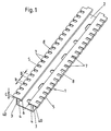
- Notches 7 extend from the edges. The transverse to the longitudinal axis of the mounting rail The measured depth of the incisions 7 is greater than the width C. of the flanged edge 5. The depth of the incisions 7 is expediently sufficient up to cheeks 3.
- the width of the two flanges 4, 40, which project laterally from the edge of a cheek 3, can be the same, so that the cross sections of the cheeks 3 and that of flanges 4, 40 going out from them, an axis of symmetry containing the cheeks 3 have (Fig. 2).
- the widths are those starting from a cheek 3 two flanges 4, 40 of different sizes.
- the following is expedient outside projecting flange 40 wider than that against the longitudinal median plane of the Mounting rail projecting flange 4 (Fig. 3, Fig. 4).
- the widths C, D of the flanged Edges 5, 6 of the flanges 4, 40 can be the same size or else also of different sizes, as shown in FIG. 3.
- the measured from cheek 3 to cheek 3 Width E of the mounting rail can be greater than its height H (Fig. 3 and Fig. 4), but also smaller (Fig. 5, Fig. 6).
- the through the flanged edges 5, 6 together with the respective cheeks 3 channels formed are expediently dimensioned so that in them Standard nuts can be held against rotation (Fig. 7). Otherwise are on the new mounting rail, fittings of the conventional type can be used. in the Web 2 openings are still recessed, suitably elongated holes, these serve to accommodate fasteners with which the mounting rail on a supporting frame or on a supporting frame or on a supporting wall can be set. The fittings on such mounting rails are used are essentially known and therefore do not need here to be further represented and disclosed. Part of it is in itself rigid brackets that are designed to be hooked in or around perforated tapes that are fastened with screws and nuts are attached to the mounting rail.
Landscapes
- Engineering & Computer Science (AREA)
- General Engineering & Computer Science (AREA)
- Architecture (AREA)
- Civil Engineering (AREA)
- Structural Engineering (AREA)
- Mechanical Engineering (AREA)
- Supports For Pipes And Cables (AREA)
- Installation Of Indoor Wiring (AREA)
Applications Claiming Priority (2)
| Application Number | Priority Date | Filing Date | Title |
|---|---|---|---|
| AT0066097U AT2698U1 (de) | 1997-10-24 | 1997-10-24 | Montageschiene |
| AT660/97U | 1997-10-24 |
Publications (1)
| Publication Number | Publication Date |
|---|---|
| EP0911564A2 true EP0911564A2 (fr) | 1999-04-28 |
Family
ID=3496467
Family Applications (1)
| Application Number | Title | Priority Date | Filing Date |
|---|---|---|---|
| EP19980119269 Withdrawn EP0911564A2 (fr) | 1997-10-24 | 1998-10-13 | Rail de montage |
Country Status (2)
| Country | Link |
|---|---|
| EP (1) | EP0911564A2 (fr) |
| AT (1) | AT2698U1 (fr) |
Citations (5)
| Publication number | Priority date | Publication date | Assignee | Title |
|---|---|---|---|---|
| DE675892C (de) | 1936-02-15 | 1939-05-20 | Lorenz Akt Ges C | Kabelleiste |
| CH348737A (fr) | 1958-12-29 | 1960-09-15 | Sierro Robert | Dispositif pour fixer sur un support des tubes, câbles ou analogues |
| US3132831A (en) | 1962-11-05 | 1964-05-12 | George F Stamper | Clip-on pipe hanger |
| DE2164991A1 (de) | 1971-12-28 | 1973-07-12 | Niedax Gmbh | Ankerschiene |
| EP0555187A1 (fr) | 1992-02-04 | 1993-08-11 | Ulrich Gantenbein | Rail de fixation, notamment pour câbles et canalisations de câble |
-
1997
- 1997-10-24 AT AT0066097U patent/AT2698U1/de not_active IP Right Cessation
-
1998
- 1998-10-13 EP EP19980119269 patent/EP0911564A2/fr not_active Withdrawn
Patent Citations (5)
| Publication number | Priority date | Publication date | Assignee | Title |
|---|---|---|---|---|
| DE675892C (de) | 1936-02-15 | 1939-05-20 | Lorenz Akt Ges C | Kabelleiste |
| CH348737A (fr) | 1958-12-29 | 1960-09-15 | Sierro Robert | Dispositif pour fixer sur un support des tubes, câbles ou analogues |
| US3132831A (en) | 1962-11-05 | 1964-05-12 | George F Stamper | Clip-on pipe hanger |
| DE2164991A1 (de) | 1971-12-28 | 1973-07-12 | Niedax Gmbh | Ankerschiene |
| EP0555187A1 (fr) | 1992-02-04 | 1993-08-11 | Ulrich Gantenbein | Rail de fixation, notamment pour câbles et canalisations de câble |
Also Published As
| Publication number | Publication date |
|---|---|
| AT2698U1 (de) | 1999-02-25 |
Similar Documents
| Publication | Publication Date | Title |
|---|---|---|
| EP0683287B1 (fr) | Rail profilé de fixation d'objets plats | |
| DE2940522C2 (de) | Anordnung von aus Metall bestehenden Riemenverbindern | |
| DE2622006B2 (de) | Energieführungskette | |
| WO1997041319A1 (fr) | Barre profilee et profile de serrage pour celle-ci | |
| DE29724813U1 (de) | Bodenelement | |
| DE3435776A1 (de) | Bauelement und aus einer vielzahl solcher elemente bestehende dachkonstruktion | |
| DE60021872T2 (de) | Befestigungs- und schaniervorrichtung für ein paneel und damit ausgestattetes paneelsystem | |
| EP0415034A2 (fr) | Chaîne porteuse pour lignes de transport d'énergie | |
| DE19854452B4 (de) | Zusammenfügbare Profilschienen zur Abdeckung, Überbrückung und/oder Einfassung der Ränder von Boden- und/oder Wandbelägen | |
| DE2935158B2 (de) | Stranggepreßtes Bauelement zum Aufbau von Wänden, insbesondere von Kraftfahrzeugen | |
| DE2418918A1 (de) | Durchbrochene decke | |
| DE4309862A1 (de) | Verbindungseinrichtung für Gitterrinnen | |
| DE10337680A1 (de) | Hohlprofil zum Befestigen von Gegenständen | |
| EP0911564A2 (fr) | Rail de montage | |
| DE2314373C3 (de) | Trägerkonstruktion | |
| DE3235609C2 (fr) | ||
| DE1659422A1 (de) | Verkleidungsbauteile | |
| DE3148777C2 (de) | Rasterdecke, insbesondere Bandrasterdecke | |
| DE3705916C2 (de) | Unterkonstruktionen für gewölbte Abhängedecken | |
| DE69815904T2 (de) | Klemmverbindungselement zum Verbinden zweier Wandprofile miteinander | |
| EP0325737B1 (fr) | Dispositif de pontage pour joint | |
| DE2707718A1 (de) | Aus platten zusammengesetzte unterdecke | |
| DE3114759A1 (de) | Weinbergpfosten | |
| DE2103853A1 (de) | Schalungsplatte für Betondecken oder Betonwände | |
| WO2003055574A1 (fr) | Profile de retenue pour lamelles, unite de profile de retenue modulaire et unite de separation, de reduction de lumiere ou de conduction de flux ainsi equipee |
Legal Events
| Date | Code | Title | Description |
|---|---|---|---|
| PUAI | Public reference made under article 153(3) epc to a published international application that has entered the european phase |
Free format text: ORIGINAL CODE: 0009012 |
|
| AK | Designated contracting states |
Kind code of ref document: A2 Designated state(s): AT BE CH CY DE DK ES FI FR GB GR IE IT LI LU MC NL PT SE |
|
| AX | Request for extension of the european patent |
Free format text: AL;LT;LV;MK;RO;SI |
|
| STAA | Information on the status of an ep patent application or granted ep patent |
Free format text: STATUS: THE APPLICATION IS DEEMED TO BE WITHDRAWN |
|
| 18D | Application deemed to be withdrawn |
Effective date: 20010503 |