EP0911509B1 - Engines of reciprocating piston type - Google Patents
Engines of reciprocating piston type Download PDFInfo
- Publication number
- EP0911509B1 EP0911509B1 EP98308616A EP98308616A EP0911509B1 EP 0911509 B1 EP0911509 B1 EP 0911509B1 EP 98308616 A EP98308616 A EP 98308616A EP 98308616 A EP98308616 A EP 98308616A EP 0911509 B1 EP0911509 B1 EP 0911509B1
- Authority
- EP
- European Patent Office
- Prior art keywords
- cylinder
- engine
- increased thickness
- cylinder block
- remainder
- Prior art date
- Legal status (The legal status is an assumption and is not a legal conclusion. Google has not performed a legal analysis and makes no representation as to the accuracy of the status listed.)
- Expired - Lifetime
Links
Images
Classifications
-
- F—MECHANICAL ENGINEERING; LIGHTING; HEATING; WEAPONS; BLASTING
- F02—COMBUSTION ENGINES; HOT-GAS OR COMBUSTION-PRODUCT ENGINE PLANTS
- F02F—CYLINDERS, PISTONS OR CASINGS, FOR COMBUSTION ENGINES; ARRANGEMENTS OF SEALINGS IN COMBUSTION ENGINES
- F02F1/00—Cylinders; Cylinder heads
- F02F1/02—Cylinders; Cylinder heads having cooling means
- F02F1/10—Cylinders; Cylinder heads having cooling means for liquid cooling
Definitions
- the present invention relates to internal combustion engines of reciprocating piston type and is concerned with the cylinder block, and particularly the cylinder barrels, of such engines. More specifically, the invention relates to engines of reciprocating piston type including a cylinder block which defines one or more cylinders, and connected to which is a cylinder head closing the cylinders, each cylinder reciprocably receiving a respective piston and being defined by a respective cylinder barrel which is integral with the remainder of the cylinder block only at, or near, one or both ends, the remainder of the length of the cylinder barrel being spaced from the remainder of the cylinder block in the radial direction by a gap which constitutes a coolant passage.
- a cylinder block having an outer wall of the water jacket connected with the cylinder barrel at an intermediate position is shown in the document EP 0 886 060 A2 (not pre-published).
- the cylinder head is conventionally connected to the cylinder block by a number of threaded bolts which pass through holes in the cylinder head and are received in threaded bores in the cylinder block.
- bolts When these bolts are tightened, local distortion of the cylinder barrels occurs which results in their shape differing slightly from the truly cylindrical. This distortion results in an increase in "blow-by", that is to say the passage of gases past the piston into the lower portion of the cylinder barrel and an increase in oil “carry over”, that is to say in the volume of oil which flows past the piston rings into the combustion space and thus in an increase in the smoke emissions from the engine.
- the cylinder barrels in order to maximise the durability of the piston and to improve the combustion characteristics, it is desirable to make the cylinder barrels as thin as possible so as to maximise the rate of heat transfer from the internal surface of the cylinder barrels to the cooling water surrounding them. It is also desirable to make them thin from the point of view of reducing the engine weight.
- an engine of the type referred to above is characterised in that the wall of the cylinder barrel affords a plurality of spaced portions of increased thickness extending over at least a proportion of its length.
- each cylinder barrel will be adjacent two or more threaded bosses and it may be provided with a portion of increased thickness in the vicinity of each adjacent threaded boss.
- Each cylinder barrel may be adjacent to four threaded bosses and be provided with four portions of increased thickness adjacent thereto.
- the portions of increased thickness or ribs preferably have a thickness in the radial direction of the associated cylinder of 2 to 6 mm greater than that of he remainder of the cylinder barrel. This means that if the cylinder barrel has a nominal thickness of e.g. 7 mm, its thickness in the region of the thickened portions will be 9 to 13 mm.
- the portions of increased thickness preferably have a dimension in the circumferential direction of the associated cylinder of 5 to 15mm.
- the ribs may extend up to the top of the cylinder barrels or alternatively they may terminate somewhat short of the top of the cylinder barrels, i.e. substantially at a position which equates to the maximum height in the cylinder reached by the piston ring, or the uppermost piston ring, i.e. the height reached at the top dead centre position, because the surface of the cylinder is not in contact with the piston rings above this point.
- the ribs may extend to the bottom of the cylinder barrels this is not necessary because the lower portions of the cylinder barrels are inherently subjected to much lower working pressures than the upper portions during the working strokes of the associated pistons. It is therefore sufficient in practice if the portions of increased thickness have a length in the axial direction of the associated cylinder of 20 to 50 mm.
- the invention resides in the recognition that the requirement for additional thickness of the cylinder barrels in order to minimise the distortion caused by the clamping loads applied by the fastening bolts can be satisfied by making the barrels thicker only locally, e.g. in the region of the clamping bolts, and not over their entire circumference.
- the cylinder barrels are locally relatively thick to provide high mechanical stiffness and generally relatively thin elsewhere to provide adequate heat transfer.
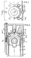
- the engine comprises a cylinder block 3 with top wall 4 affording a plane substantially rectangular upper surface 5, two side walls 6, two end walls (not shown) and an opening at the base 8 which is covered by an oil pan (not shown).
- integralally cast with the top wall 4 and base 8 are four equispaced cylinder barrels 10 of which only one is shown and which are spaced from the side walls and open out through the upper surface to define respective cylinders 12.
- Connected to the cylinder block is a cylinder head 14 with a lower surface 16 which firmly abuts the upper surface 5 of the cylinder block with the interposition of a cylinder head gasket (not shown).
- the cylinder head 14 is connected to the cylinder block 2 by a plurality of threaded fastening bolts 24, of which only one is shown in Figure 2.
- Each bolt 24 passes through a respective hole 26 in the cylinder head and the upper surface of the cylinder block and is received in a respective internally threaded boss 28 integral with the top and base of the block.
- bosses associated with each cylinder there are six bosses associated with each cylinder, two lying on a diametral line extending perpendicular to the length of the cylinder block and the other four being associated in pairs on opposite sides of the diametral line and associated also with the adjacent cylinder.
- the six bosses associated with each cylinder are substantially equiangularly offset from each other with respect to the axis of the cylinder barrel.
- the cylinder barrels are spaced from the side and end walls of the cylinder barrel to define a coolant space 30 through which, in use, coolant flows to maintain the cylinder barrels and the pistons within them at an acceptable temperature.
- the cylinder barrels constitute hollow cylinders which are integral with the remainder of the cylinder block at their ends and have a nominal wall thickness of typically 7mm.
- each cylinder barrel is provided with four portions 32 of increased thickness in the nature of longitudinally extending ribs. Each rib extends downwardly about 30 to 50mm from the underside of the top wall 4 of the cylinder block.
- Each thickened portion is typically 10mm thick, i.e. 3mm thicker than the remainder of the barrel, and has a circumferential extent of about 10mm.
- the cylinder liners are subject to maximum distortion in the vicinity of the bolts, i.e. in the vicinity of the bosses.
- the ribs are conveniently located as close to the bosses as possible. Ideally the ribs would be radially aligned with the bosses but this may lead to an unacceptable constriction of the coolant space at these points and it is therefore necessary in practice for the ribs to be slightly angularly offset from the bosses by e.g. 10° to 20°.
- ribs and fastening bolts may be varied as required.
- the ribs need not necessarily extend down from the underside of the top wall of the cylinder block and may instead extend down from that position a little lower down which is reached by the upper piston ring on the associated piston when at the top dead centre position.
- the four ribs 30 are not equiangularly spaced in the described embodiment but it would be possible for them to be so.
Landscapes
- Engineering & Computer Science (AREA)
- Chemical & Material Sciences (AREA)
- Combustion & Propulsion (AREA)
- Mechanical Engineering (AREA)
- General Engineering & Computer Science (AREA)
- Cylinder Crankcases Of Internal Combustion Engines (AREA)
- Pistons, Piston Rings, And Cylinders (AREA)
Applications Claiming Priority (2)
| Application Number | Priority Date | Filing Date | Title |
|---|---|---|---|
| GB9722449 | 1997-10-23 | ||
| GBGB9722449.7A GB9722449D0 (en) | 1997-10-23 | 1997-10-23 | Engines of reciprocating piston type |
Publications (2)
| Publication Number | Publication Date |
|---|---|
| EP0911509A1 EP0911509A1 (en) | 1999-04-28 |
| EP0911509B1 true EP0911509B1 (en) | 2002-12-18 |
Family
ID=10821007
Family Applications (1)
| Application Number | Title | Priority Date | Filing Date |
|---|---|---|---|
| EP98308616A Expired - Lifetime EP0911509B1 (en) | 1997-10-23 | 1998-10-21 | Engines of reciprocating piston type |
Country Status (5)
| Country | Link |
|---|---|
| US (1) | US6035813A (ja) |
| EP (1) | EP0911509B1 (ja) |
| JP (1) | JPH11200942A (ja) |
| DE (1) | DE69810236T2 (ja) |
| GB (1) | GB9722449D0 (ja) |
Families Citing this family (4)
| Publication number | Priority date | Publication date | Assignee | Title |
|---|---|---|---|---|
| GB0123854D0 (en) | 2001-10-04 | 2001-11-28 | Ricardo Consulting Eng | Engines of reciprocating piston type |
| JP2010156202A (ja) * | 2007-04-05 | 2010-07-15 | Yamaha Motor Co Ltd | エンジン |
| US20160265475A1 (en) * | 2015-03-11 | 2016-09-15 | Caterpillar Inc. | Cylinder Head/Cylinder Block Joint |
| DE102015219638A1 (de) * | 2015-10-09 | 2017-04-13 | Volkswagen Aktiengesellschaft | Zylinderkurbelgehäuse für eine Hubkolben-Brennkraftmaschine und Hubkolben-Brennkraftmaschine |
Citations (1)
| Publication number | Priority date | Publication date | Assignee | Title |
|---|---|---|---|---|
| EP0886060A2 (en) * | 1997-06-16 | 1998-12-23 | Nissan Motor Company Limited | Engine cylinder block |
Family Cites Families (4)
| Publication number | Priority date | Publication date | Assignee | Title |
|---|---|---|---|---|
| FR1046761A (fr) * | 1951-03-22 | 1953-12-09 | Siemag Vertriebsgesellschaft | Cylindre de travail pour moteurs à combustion interne |
| FR1060871A (fr) * | 1952-05-09 | 1954-04-07 | Res Engineering Corp | Perfectionnements relatifs aux cylindres pour moteurs à combustion interne |
| DE1026127B (de) * | 1957-03-26 | 1958-03-13 | Henschel & Sohn Gmbh | Arbeitszylinder von Verbrennungskraftmaschinen mit trockenen Buechsen |
| JPH1047153A (ja) * | 1996-08-01 | 1998-02-17 | Toyota Motor Corp | オープンデッキ型シリンダブロック |
-
1997
- 1997-10-23 GB GBGB9722449.7A patent/GB9722449D0/en not_active Ceased
-
1998
- 1998-10-21 DE DE69810236T patent/DE69810236T2/de not_active Expired - Lifetime
- 1998-10-21 EP EP98308616A patent/EP0911509B1/en not_active Expired - Lifetime
- 1998-10-22 JP JP10300726A patent/JPH11200942A/ja active Pending
- 1998-10-22 US US09/176,820 patent/US6035813A/en not_active Expired - Fee Related
Patent Citations (1)
| Publication number | Priority date | Publication date | Assignee | Title |
|---|---|---|---|---|
| EP0886060A2 (en) * | 1997-06-16 | 1998-12-23 | Nissan Motor Company Limited | Engine cylinder block |
Also Published As
| Publication number | Publication date |
|---|---|
| JPH11200942A (ja) | 1999-07-27 |
| DE69810236D1 (de) | 2003-01-30 |
| GB9722449D0 (en) | 1997-12-24 |
| EP0911509A1 (en) | 1999-04-28 |
| US6035813A (en) | 2000-03-14 |
| DE69810236T2 (de) | 2003-11-06 |
Similar Documents
| Publication | Publication Date | Title |
|---|---|---|
| US4106444A (en) | Individual cylinder head | |
| US4993375A (en) | Engine cylinder head cover | |
| KR880002487B1 (ko) | 선외기용 수냉식 디젤 기관 | |
| US4291650A (en) | Cylinder head for compression-ignition internal combustion engine | |
| EP0928891B1 (en) | Cylinder block structure | |
| US8256389B2 (en) | Cylinder block | |
| US4616603A (en) | Cylinder liner for a multi-cylinder internal combustion engine and an engine block therefor | |
| GB2058912A (en) | Internal combustion engine with integral upper cylinder section and head | |
| CN100368674C (zh) | 内燃机用单部件冷却通道活塞 | |
| US7000584B1 (en) | Thermally insulated cylinder liner | |
| US6973907B2 (en) | Cylinder block for internal-combustion engine | |
| JPH06235349A (ja) | 湿式シリンダライナ | |
| US4805563A (en) | Block construction of engine | |
| EP0911509B1 (en) | Engines of reciprocating piston type | |
| US7654234B2 (en) | Barrel engine block assembly | |
| US6354260B1 (en) | Replaceable combustion chamber insert for two cycle engines and method for manufacturing same | |
| EP0075257B1 (en) | Cylinder block | |
| US6318311B1 (en) | Cylinder-injection type two cycle combustion engine | |
| US20030172884A1 (en) | Cylinder block and die-casting method for producing same | |
| EP0758715A1 (en) | A piston for diesel engines | |
| US6886504B2 (en) | Engine of reciprocating piston type | |
| US5937803A (en) | Engine cylinder block | |
| US11859575B2 (en) | Arrangement for an internal combustion engine and method for cooling such an arrangement | |
| US7225767B1 (en) | Conversion of an air-cooled engine to liquid cooling | |
| JPS643791Y2 (ja) |
Legal Events
| Date | Code | Title | Description |
|---|---|---|---|
| PUAI | Public reference made under article 153(3) epc to a published international application that has entered the european phase |
Free format text: ORIGINAL CODE: 0009012 |
|
| AK | Designated contracting states |
Kind code of ref document: A1 Designated state(s): DE FR GB IT SE |
|
| AX | Request for extension of the european patent |
Free format text: AL;LT;LV;MK;RO;SI |
|
| 17P | Request for examination filed |
Effective date: 19991022 |
|
| AKX | Designation fees paid |
Free format text: DE FR GB IT SE |
|
| 17Q | First examination report despatched |
Effective date: 20011010 |
|
| GRAG | Despatch of communication of intention to grant |
Free format text: ORIGINAL CODE: EPIDOS AGRA |
|
| GRAG | Despatch of communication of intention to grant |
Free format text: ORIGINAL CODE: EPIDOS AGRA |
|
| GRAH | Despatch of communication of intention to grant a patent |
Free format text: ORIGINAL CODE: EPIDOS IGRA |
|
| GRAH | Despatch of communication of intention to grant a patent |
Free format text: ORIGINAL CODE: EPIDOS IGRA |
|
| GRAA | (expected) grant |
Free format text: ORIGINAL CODE: 0009210 |
|
| AK | Designated contracting states |
Kind code of ref document: B1 Designated state(s): DE FR GB IT SE |
|
| REG | Reference to a national code |
Ref country code: GB Ref legal event code: FG4D |
|
| REF | Corresponds to: |
Ref document number: 69810236 Country of ref document: DE Date of ref document: 20030130 Kind code of ref document: P Ref document number: 69810236 Country of ref document: DE Date of ref document: 20030130 |
|
| REG | Reference to a national code |
Ref country code: SE Ref legal event code: TRGR |
|
| ET | Fr: translation filed | ||
| PGFP | Annual fee paid to national office [announced via postgrant information from national office to epo] |
Ref country code: SE Payment date: 20031007 Year of fee payment: 6 |
|
| PLBE | No opposition filed within time limit |
Free format text: ORIGINAL CODE: 0009261 |
|
| STAA | Information on the status of an ep patent application or granted ep patent |
Free format text: STATUS: NO OPPOSITION FILED WITHIN TIME LIMIT |
|
| 26N | No opposition filed |
Effective date: 20030919 |
|
| PG25 | Lapsed in a contracting state [announced via postgrant information from national office to epo] |
Ref country code: SE Free format text: LAPSE BECAUSE OF NON-PAYMENT OF DUE FEES Effective date: 20041022 |
|
| EUG | Se: european patent has lapsed | ||
| PG25 | Lapsed in a contracting state [announced via postgrant information from national office to epo] |
Ref country code: IT Free format text: LAPSE BECAUSE OF NON-PAYMENT OF DUE FEES Effective date: 20051021 |
|
| PGFP | Annual fee paid to national office [announced via postgrant information from national office to epo] |
Ref country code: GB Payment date: 20061129 Year of fee payment: 9 |
|
| GBPC | Gb: european patent ceased through non-payment of renewal fee |
Effective date: 20071021 |
|
| PG25 | Lapsed in a contracting state [announced via postgrant information from national office to epo] |
Ref country code: GB Free format text: LAPSE BECAUSE OF NON-PAYMENT OF DUE FEES Effective date: 20071021 |
|
| PGFP | Annual fee paid to national office [announced via postgrant information from national office to epo] |
Ref country code: DE Payment date: 20091015 Year of fee payment: 12 |
|
| PGFP | Annual fee paid to national office [announced via postgrant information from national office to epo] |
Ref country code: FR Payment date: 20091029 Year of fee payment: 12 |
|
| PG25 | Lapsed in a contracting state [announced via postgrant information from national office to epo] |
Ref country code: FR Free format text: LAPSE BECAUSE OF NON-PAYMENT OF DUE FEES Effective date: 20101102 |
|
| REG | Reference to a national code |
Ref country code: FR Ref legal event code: ST Effective date: 20110630 |
|
| REG | Reference to a national code |
Ref country code: DE Ref legal event code: R119 Ref document number: 69810236 Country of ref document: DE Effective date: 20110502 |
|
| PG25 | Lapsed in a contracting state [announced via postgrant information from national office to epo] |
Ref country code: DE Free format text: LAPSE BECAUSE OF NON-PAYMENT OF DUE FEES Effective date: 20110502 |