EP0911238A1 - Transport device for containers on railroad cars - Google Patents
Transport device for containers on railroad cars Download PDFInfo
- Publication number
- EP0911238A1 EP0911238A1 EP98117569A EP98117569A EP0911238A1 EP 0911238 A1 EP0911238 A1 EP 0911238A1 EP 98117569 A EP98117569 A EP 98117569A EP 98117569 A EP98117569 A EP 98117569A EP 0911238 A1 EP0911238 A1 EP 0911238A1
- Authority
- EP
- European Patent Office
- Prior art keywords
- frame
- base frame
- transport device
- wagon
- transport
- Prior art date
- Legal status (The legal status is an assumption and is not a legal conclusion. Google has not performed a legal analysis and makes no representation as to the accuracy of the status listed.)
- Withdrawn
Links
Images

Classifications
-
- B—PERFORMING OPERATIONS; TRANSPORTING
- B61—RAILWAYS
- B61D—BODY DETAILS OR KINDS OF RAILWAY VEHICLES
- B61D3/00—Wagons or vans
- B61D3/16—Wagons or vans adapted for carrying special loads
- B61D3/20—Wagons or vans adapted for carrying special loads for forwarding containers
-
- B—PERFORMING OPERATIONS; TRANSPORTING
- B61—RAILWAYS
- B61D—BODY DETAILS OR KINDS OF RAILWAY VEHICLES
- B61D3/00—Wagons or vans
- B61D3/04—Wagons or vans with movable floors, e.g. rotatable or floors which can be raised or lowered
-
- B—PERFORMING OPERATIONS; TRANSPORTING
- B61—RAILWAYS
- B61D—BODY DETAILS OR KINDS OF RAILWAY VEHICLES
- B61D47/00—Loading or unloading devices combined with vehicles, e.g. loading platforms, doors convertible into loading and unloading ramps
Landscapes
- Engineering & Computer Science (AREA)
- Transportation (AREA)
- Mechanical Engineering (AREA)
- Loading Or Unloading Of Vehicles (AREA)
Abstract
Description
Die Erfindung betrifft eine Transportvorrichtung für Container auf Eisenbahnwaggons, mit einem, auf dem Waggonrahmen vorgesehenen Drehrahmen, der Laufbahnen für Rollen der Container sowie eine Antriebseinrichtung zum Drehen des Drehrahmens aufweist und mit einer den Drehrahmen in seiner eingeschwenkten Transportstellung sichernden Verriegelungseinrichtung.The invention relates to a transport device for containers on railway wagons, with a rotating frame provided on the wagon frame, the tracks for Rolling the container and a drive device for rotating the rotating frame has and with a the rotating frame in its pivoted transport position securing locking device.
Solche Transportvorrichtungen sind z.B. aus der DE-U-91 01 186 bekannt. Sie ermöglichen die Übergabe von Containern vom LKW auf den Eisenbahnwaggon und umgekehrt ausschließlich mittels LKW-seitigen hydraulischen Be- und Entladesystemen. Jegliche Kräne, Umladeanlagen oder Spreader entfallen. Mit diesem Konzept ist ein reibungsloser Materialtransport durch Anbindung des Straßennetzes an das Schienennetz möglich. Der generelle Einsatz scheiterte aber bisher daran, daß diese speziellen Eisenbahnwaggons mit fest aufgebauten Drehrahmen, durch die konstruktiv festgesetzte Beladehöhe nur an bestimmten Ladestraßen einsetzbar sind, was einem durchgängig wirtschaftlichen Einsatz im Wege stand. Ein weiterer Nachteil besteht darin, daß diese speziellen Eisenbahnwaggons nur für Abrollcontainer und daher nicht für andere Güter und andere Container benutzt werden können.Such transport devices are e.g. known from DE-U-91 01 186. she enable the transfer of containers from the truck to the railway wagon and conversely, only by means of hydraulic loading and unloading systems on the truck side. No cranes, transshipment systems or spreaders are required. With this concept is a smooth material transport by connecting the road network to the Rail network possible. The general application has so far failed because of this special railway wagons with fixed rotating frames, through which constructive fixed loading height can only be used on certain loading streets, which one consistent economic use in the way. Another disadvantage is in that these special railway wagons only for roll-off containers and therefore not can be used for other goods and other containers.
Aufgabe der Erfindung ist es daher, eine Transportvorrichtung der eingangs genannten Art derart auszubilden, daß die Eisenbahnwaggons auch für andere Containertransporte benutzt werden können und unterschiedliche Eisenbahnwaggons, insbesondere mit unterschiedlichen Behälteraufstandshöhen und Beladehöhen zum Einsatz kommen können.The object of the invention is therefore a transport device of the aforementioned Type in such a way that the railway wagons also for other container transports can be used and different railway wagons, especially with different container contact heights and loading heights are used can.
Diese Aufgabe wird bei einer Transportvorrichtung der eingangs genannten Art dadurch gelöst, daß der Drehrahmen auf einem Grundrahmen drehbar gelagert ist, der seinerseits auf dem Waggonrahmen abnehmbar aufgesetzt und wenigstens an einem Ende mittels einer Abhebesicherungseinrichtung befestigt ist.This object is achieved in a transport device of the type mentioned solved that the rotating frame is rotatably mounted on a base frame, the in turn detachably placed on the wagon frame and at least on one End is attached by means of an anti-lift device.
Der Vorteil der Erfindung ist einleuchtend. Es muß nicht mehr eine große Zahl von mit Drehrahmen ausgestatteten Eisenbahnwaggons bevorratet werden, vielmehr werden herkömmliche Eisenbahnwaggons bei Bedarf mit den erfindungsgemäßen Dreheinheiten bestückt, die den Grundrahmen mit Drehrahmen, Verriegelungseinrichtung und Abhebesicherungseinrichtung umfassen. Nach dem Transport des Abrollcontainers kann die Dreheinheit wieder vom Waggon gelöst und zwischengelagert werden. Der Eisenbahnwaggon ist dann wieder universell für den Transport anderer Container einsetzbar. Statt der Bevorratung von speziellen, mit Drehrahmen ausgestatteten Eisenbahnwaggons an jeder Umschlagstelle braucht lediglich noch eine gewisse Zahl von Dreheinheiten auf Lager gehalten zu werden. Die Wirtschaftlichkeit wird dadurch maßgeblich erhöht.The advantage of the invention is obvious. There is no longer a large number of having Railway carriages equipped with rotating frames are stored, rather conventional railway wagons if required with the turntables according to the invention equipped, which the base frame with rotating frame, locking device and Lift protection device include. After the roll-off container has been transported the turntable is removed from the wagon and stored temporarily. Of the Railway wagons are again universal for the transport of other containers applicable. Instead of stocking special, equipped with rotating frames Railway wagons at each transshipment point only need a certain number to be kept in stock by rotating units. The economy is thereby significantly increased.
Bevorzugt weist der Grundrahmen bei der erfindungsgemäßen Transporteinrichtung ISO-Eckbeschläge auf, die auf die ISO-Zapfen des Waggonrahmens passen. Dadurch ist es möglich, die separate Dreheinheit wie einen herkömmlichen Container auf den Eisenbahnwaggon aufzusetzen, wobei die Abhebesicherungseinrichtung dafür sorgt, daß der Grundrahmen am Waggonrahmen abkippsicher befestigt ist. Der Drehrahmen kann also nach dem Ausschwenken genauso belastet werden, wie dies mit den bekannten Eisenbahnwaggons möglich ist, bei denen der Drehrahmen am Waggonrahmen unlösbar gelagert ist.The base frame preferably has in the transport device according to the invention ISO corner fittings that fit on the ISO pins of the wagon frame. This is it is possible to mount the separate turntable like a conventional container To set up the railway wagon, with the anti-lifting device ensuring that the base frame is secured against tipping over on the wagon frame. The rotating frame can be loaded after swiveling just like this with the known railroad cars is possible, in which the rotating frame on The wagon frame is stored non-detachably.
Vorteilhafte Weiterbildungen der Erfindung bestehen noch darin, daß die Abhebesicherungseinrichtung am Grundrahmen längsverstellbar angeordnet und zum Zusammenwirken mit beidseitigen Längsträgern des Waggonrahmens ausgebildet ist, daß die Abhebesicherungseinrichtung zwei prinzipiell gleich ausgebildete beidseitig am Grundrahmen vorgesehene Greiferanordnungen aufweist, wobei jede Greiferanordnung vorzugsweise an einem längsverstellbaren Schlitten angeordnet ist, der in einer Längsschiebeführung des Grundrahmens geführt und in wählbaren Positionen feststellbar ist. Dadurch ist es möglich, die Transportvorrichtung für unterschiedliche Eisenbahnwaggons zu verwenden, indem die Befestigungspositionen für die Greiferanordnungen in weiten Bereichen auswählbar sind. Außerdem ist vorzugsweise jede Greiferanordnung am Grundrahmen querverstellbar. Damit ergibt sich eine universelle Anpaßbarkeit der Abhebesicherungseinrichtung an die jeweiligen konstruktiven Gegebenheiten des Eisenbahnwaggons.Advantageous developments of the invention consist in that the Lift-off device arranged on the base frame in a longitudinally adjustable manner and for Interaction with the longitudinal members of the wagon frame is formed, that the anti-lift device two basically the same design on both sides on Has base frame provided gripper assemblies, each gripper assembly is preferably arranged on a longitudinally adjustable carriage which in a Longitudinal sliding guide of the base frame and in selectable positions is noticeable. This makes it possible to use the transport device for different Railway wagons to be used by the mounting positions for the Gripper arrangements can be selected in a wide range. It is also preferred each gripper arrangement on the base frame can be traversed. This results in a universal adaptability of the anti-lift device to the respective constructive conditions of the railway wagon.
Eine weitere vorteilhafte Weiterbildung der Erfindung besteht darin, daß die Abhebesicherungseinrichtung eine Offenstellung und eine Funktionsstellung aufweist und beim Aufsetzen des Grundrahmens auf den Waggonrahmen oder beim erstmaligen Ausschwenken des Drehrahmens selbsttätig in ihre Funktionsstellung gelangt. Dieses Merkmal gewinnt insbesondere dann an Bedeutung, wenn die Dreheinheit von den Eisenbahnwaggons häufig abgenommen und wieder aufgesetzt wird. Dank der automatischen Funktion der Abhebesicherungseinrichtung können keine Bedienungsfehler mehr auftreten. Vorzugsweise werden die Greiferanordnungen von Verstellmechanismen betätigt, die je einen Federspeicher umfassen, der in der Offenstellung der Abhebesicherungseinrichtung vorgespannt und mittels einer Auslöseeinrichtung beim Aufsetzen des Grundrahmens oder beim erstmaligen Ausschwenken des Drehrahmens aktivierbar ist und die Schwenkklaue an der Unterseite eines Flansches des Längsträgers kraftschlüssig in Anlage hält. Der Federspeicher ist vorzugsweise als druckluftbetätigter Federspeicherzylinder ausgebildet und die Auslöseeinrichtung umfaßt ein Entlüftungsventil am Grundrahmen, das in der Transportstellung des Drehrahmens geschlossen gehalten und beim Verschwenken aus der Transportstellung automatisch geöffnet wird. Another advantageous development of the invention is that the Lift protection device has an open position and a functional position and when placing the base frame on the wagon frame or when starting for the first time Swiveling out of the rotating frame automatically reaches its functional position. This Characteristic is particularly important if the turntable is different from the Railway wagons are often removed and replaced. thanks to the automatic function of the anti-lift device cannot Operating errors occur more. The gripper arrangements are preferably of Adjustment mechanisms actuated, each comprising a spring accumulator, which in the Open position of the anti-lift device biased and by means of a Tripping device when attaching the base frame or when starting for the first time Swiveling the rotating frame can be activated and the swivel claw on the Holds the underside of a flange of the side member non-positively in contact. Of the Spring accumulator is preferably designed as a compressed air actuated spring accumulator cylinder and the trigger means comprises a vent valve on the base frame, which in the Transport position of the rotating frame is kept closed and when swiveling out the transport position is opened automatically.
Anhand der Zeichnung, die ein Ausführungsbeispiel darstellt, wird die Erfindung noch näher beschrieben.Based on the drawing, which represents an embodiment, the invention will described in more detail.
Es zeigt:
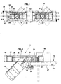
- FIG. 1
- Eine Draufsicht auf einen Eisenbahnwaggon mit lösbar aufgesetzten Dreheinheiten,
- FIG. 2
- einen Querschnitt einer aus Grundrahmen und Drehrahmen bestehenden Dreheinheit auf einem strichpunktiert dargestellten Waggon,
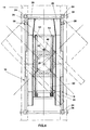
- FIG. 3
- eine Querschnittansicht eines Ausschnittes des Grundrahmens mit Veranschaulichung der Abhebesicherungseinrichtung im größeren Maßstab, und
- FIG. 4
- eine Draufsicht auf die Dreheinheit mit strichpunktierter Darstellung des Waggonrahmens
- FIG. 1
- A top view of a railroad car with detachable rotating units,
- FIG. 2nd
- 1 shows a cross section of a rotating unit consisting of a base frame and rotating frame on a carriage shown in broken lines,
- FIG. 3rd
- a cross-sectional view of a section of the base frame showing the anti-lift device on a larger scale, and
- FIG. 4th
- a plan view of the turntable with dash-dotted representation of the wagon frame
Ein Eisenbahnwaggon 10 (FIG. 1) hat einen Waggonrahmen 12 mit zwei Längsträgern
14, auf denen zwei Transportvorrichtungen 16 lösbar befestigt sind. Jede
Transportvorrichtung 16 besteht aus einem Grundrahmen 18 und einem Drehrahmen
20, der mittels eines Drehkranzes 22 am Grundrahmen 18 gelagert ist. Der
Grundrahmen 18 weist ISO-Eckbeschläge 24 auf, die an den vier ISO-Zapfen 26 jedes
Containerfeldes des Waggonrahmens 12 festgelegt sind. Der Drehrahmen 20 ist in
seiner Transportstellung (FIG. 4) mittels Verriegelungseinrichtungen 28 am rechteckigen
Grundrahmen 18 gegen Verschwenken verriegelt und weist Laufbahnen 30 für
heckseitige Bodenrollen sowie durchgehende Winkelschienen 53 zur Aufnahme und
Führung eines Abrollcontainers (nicht dargestellt) auf. Nach Lösen der Verriegelungen
28 kann der Drehrahmen 20 mittels eines nicht dargestellten manuellen, mechanischen
oder hydraulischen Antriebes beidseitig um mindestens 45° nach außen geschwenkt
werden, wie in FIG. 4 gestrichelt dargestellt ist.A railway wagon 10 (FIG. 1) has a
Um ein Kippen der aus Grundrahmen 18 und Drehrahmen 20 bestehenden
Transportvorrichtung 16 bei Belastung des ausgeschwenkten Drehrahmens 20 zu
verhindern, ist eine Abhebesicherungseinrichtung 32 am des Grundrahmens 18
vorgesehen, die zwei seitliche Greifer 34 umfaßt, welche den Grundrahmen 18 an den
oberen Flanschen 37 der Längsträger 14 des Waggonrahmens 12 festklemmen, wie für
den rechten Greifer 34 in FIG. 3 veranschaulicht ist. Jeder Greifer 34 besteht aus
einem U-förmigen Haken, der an einem Schlitten 36 schwenkbar gelagert ist, der
seinerseits in U-Führungen 38 längsverstellbar geführt ist, die am Längsschenkel 40 des
Grundrahmens 18 und einem dazu parallelen Hilfsschenkel 42 befestigt sind. Am
Greifer 34 greift die Zugstange 44 eines Federspeicherzylinders 46 an, der seinerseits
mittels eines Winkelbleches am Schlitten 36 befestigt ist. Dank der Längsverstellbarkeit
des Schlittens 36 kann der Greifer 34 an eine passende Längsposition des Längsträgers
14 des Waggonrahmens 12 verschoben und in dieser Position wahlweise festgelegt
werden, um den Tragflansch 37 des Längsträgers 14 untergreifen zu können. In FIG. 3
ist die Zugstange 44 des Federspeicherzylinders 46 so weit eingefahren, daß sich der
Greifer 34 in seiner Funktionsstellung befindet und den Grundrahmen 18 am oberen
Flansch 37 des Waggonrahmens 12 kraftschlüssig festspannt. Zur Feineinstellung der
Klemmposition des Greifers 34 dient ein Gewindebolzen 47 am Bodenschenkel des
Greifers 34.To tilt the existing of the
Zur Anpassung an verschiedene Ausführungen von Eisenbahnwaggons ist die
Schwenklagerung des Greifers 34 am Schlitten 36 einschließlich der Halterung des
Federspeicherzylinders 46 quer verschiebbar und in geeigneter Schiebestellung
feststellbar. To adapt to different versions of railway wagons is the
Pivotal mounting of the
Wie FIG. 2 veranschaulicht, sind ein linksseitiger und ein rechtsseitiger Greifer 34
vorgesehen, deren zugehörige Federspeicherzylinder 46 an ein Schnellentlüftungsventil
48 über Druckluftleitungen 50 angeschlossen sind. Ein am Drehrahmen 20 befestigter
Hebel 52 betätigt das Entlüftungsventil 48.As FIG. 2, left and
Beim Ausschwenken des Drehrahmens 20 vor der ersten Beladung mit einem
Abrollcontainer sorgt der Hebel 52 für eine selbsttätige Schnellentlüftung der beiden
Federspeicherzylinder, so daß die Greifer 34 den Grundrahmen 18 am Waggonrahmen
12 festklemmen. Zum Abheben der Transportvorrichtung 16 vom Waggonrahmen 12
werden die beiden Federspeicherzylinder mittels der Druckluftanlage des LKW unter
Druck gesetzt, sodaß die Greifer 34 in die in FIG. 3 gestrichelt dargestellte
Offenstellung geschwenkt werden.When swiveling the rotating
Im geöffneten Zustand der Abhebesicherungseinrichtung kann die Transportvorrichtung
16, bestehend aus Grundrahmen 18 und Drehrahmen 20 vom Waggonrahmen 12
mittels eines Kranes abgenommen und gelagert werden. Der Eisenbahnwaggon 10 kann
dann zum Transport anderer Güter, insbesondere von ISO-Containern, verwendet
werden.In the open state of the anti-lift device, the transport device can
16, consisting of
Anstelle der in den Zeichnungen dargestellten Abhebesicherungseinrichtung lassen sich auch hydraulische, pneumatische oder mechanische Spannvorrichtungen verwenden, z.B. Schraubzwingen, Kniehebel und Spanngurte.Instead of the anti-lift device shown in the drawings also use hydraulic, pneumatic or mechanical clamping devices, e.g. Screw clamps, toggle levers and tension belts.
Die Verriegelungseinrichtungen 28 des Abrollcontainers auf dem Drehrahmen 20 sind
bekannt und können Riegelnasenanschläge, Zapfenverschlüsse oder
Klauenverriegelungen umfassen.The
Claims (10)
Applications Claiming Priority (2)
| Application Number | Priority Date | Filing Date | Title |
|---|---|---|---|
| DE19747085 | 1997-10-24 | ||
| DE1997147085 DE19747085A1 (en) | 1997-10-24 | 1997-10-24 | Transport device for containers on railway wagons |
Publications (1)
| Publication Number | Publication Date |
|---|---|
| EP0911238A1 true EP0911238A1 (en) | 1999-04-28 |
Family
ID=7846554
Family Applications (1)
| Application Number | Title | Priority Date | Filing Date |
|---|---|---|---|
| EP98117569A Withdrawn EP0911238A1 (en) | 1997-10-24 | 1998-09-16 | Transport device for containers on railroad cars |
Country Status (2)
| Country | Link |
|---|---|
| EP (1) | EP0911238A1 (en) |
| DE (1) | DE19747085A1 (en) |
Cited By (3)
| Publication number | Priority date | Publication date | Assignee | Title |
|---|---|---|---|---|
| EP1982891A1 (en) * | 2007-04-20 | 2008-10-22 | CBW Holding B.V. | Swivel frame, and rail vehicle |
| CN104828101A (en) * | 2015-02-09 | 2015-08-12 | 郭卫康 | Motor vehicle in-situ steering device and method for train |
| CN110803087A (en) * | 2019-09-17 | 2020-02-18 | 徐州市凯诺机械有限公司 | Movable steering platform of engineering mechanical equipment |
Citations (4)
| Publication number | Priority date | Publication date | Assignee | Title |
|---|---|---|---|---|
| DE1257821B (en) * | 1963-12-03 | 1968-01-04 | Niesky Waggonbau Veb | Turntable, especially for rail transport |
| GB2108473A (en) * | 1981-11-02 | 1983-05-18 | Partek Ab | Method and equipment for transportation of containers on railway waggons |
| DE9101186U1 (en) | 1991-02-02 | 1991-04-25 | Roland - Tankbau Gmbh & Co Kg, 2080 Pinneberg, De | |
| EP0516583A1 (en) * | 1991-05-27 | 1992-12-02 | Tuchschmid Ag | Railway wagon for cargo-carriers |
Family Cites Families (5)
| Publication number | Priority date | Publication date | Assignee | Title |
|---|---|---|---|---|
| US2344650A (en) * | 1942-11-05 | 1944-03-21 | Howard M Sloat | Loading apparatus |
| NL262359A (en) * | 1960-04-11 | |||
| DE8710264U1 (en) * | 1987-07-27 | 1987-09-17 | Rocholl, Juergen, 2081 Appen, De | |
| DE9401032U1 (en) * | 1994-01-21 | 1994-03-17 | Schreiner Geb | Carrying device for loading pallets |
| DE29500941U1 (en) * | 1995-01-21 | 1995-05-04 | Westrick Ludger Dipl Ing | Support frame for a roll-off or settling container |
-
1997
- 1997-10-24 DE DE1997147085 patent/DE19747085A1/en not_active Withdrawn
-
1998
- 1998-09-16 EP EP98117569A patent/EP0911238A1/en not_active Withdrawn
Patent Citations (4)
| Publication number | Priority date | Publication date | Assignee | Title |
|---|---|---|---|---|
| DE1257821B (en) * | 1963-12-03 | 1968-01-04 | Niesky Waggonbau Veb | Turntable, especially for rail transport |
| GB2108473A (en) * | 1981-11-02 | 1983-05-18 | Partek Ab | Method and equipment for transportation of containers on railway waggons |
| DE9101186U1 (en) | 1991-02-02 | 1991-04-25 | Roland - Tankbau Gmbh & Co Kg, 2080 Pinneberg, De | |
| EP0516583A1 (en) * | 1991-05-27 | 1992-12-02 | Tuchschmid Ag | Railway wagon for cargo-carriers |
Cited By (5)
| Publication number | Priority date | Publication date | Assignee | Title |
|---|---|---|---|---|
| EP1982891A1 (en) * | 2007-04-20 | 2008-10-22 | CBW Holding B.V. | Swivel frame, and rail vehicle |
| NL2000602C2 (en) * | 2007-04-20 | 2008-10-24 | Cbw Holding B V | Turning frame, and rail vehicle. |
| EP2374682A1 (en) * | 2007-04-20 | 2011-10-12 | CBW Holding B.V. | Swivel frame, and rail vehicle |
| CN104828101A (en) * | 2015-02-09 | 2015-08-12 | 郭卫康 | Motor vehicle in-situ steering device and method for train |
| CN110803087A (en) * | 2019-09-17 | 2020-02-18 | 徐州市凯诺机械有限公司 | Movable steering platform of engineering mechanical equipment |
Also Published As
| Publication number | Publication date |
|---|---|
| DE19747085A1 (en) | 1999-04-29 |
Similar Documents
| Publication | Publication Date | Title |
|---|---|---|
| EP0298382B1 (en) | Container for storage and transportation of especially bulk material, such as rubble, garbage, industrial waste and the like | |
| DE10255843A1 (en) | Telescopic conveyor | |
| EP2185382A1 (en) | Apparatus for securing a container on a platform of a transport vehicle | |
| EP2786940A1 (en) | Loading station for transport bags for the suspended transport of goods | |
| DE60119126T2 (en) | DEVICE FOR TIGHTENING AND TRANSPORTING FLAT MATERIAL | |
| DE2038943A1 (en) | Railway wagons for automobile transport | |
| DE1029027B (en) | Collapsible support for a cargo container, especially a semi-trailer | |
| EP0911238A1 (en) | Transport device for containers on railroad cars | |
| DE3927646A1 (en) | Picking up and setting down loads - involves support frame forming tunnel for rolling frame | |
| EP0623498A1 (en) | Loading device for load-carriers | |
| DE10246157A1 (en) | Rail guided trolley system has upper and lower wheels to engage upper or lower rails with opposite gradients | |
| DE19751938C2 (en) | Device for securing loads on the loading area of vehicles | |
| DE102012108557A1 (en) | Load securing arrangement in an inloader transport vehicle and corresponding method for load securing | |
| EP3623218A1 (en) | Carriage for a transport vehicle for transporting rolling containers | |
| EP1587728B1 (en) | Stanchion with an integrated device for securing a load, in particular for tarpaulin-covered transport vehicles | |
| DE2312402B1 (en) | Device for locking a freight container on a base, in particular a chassis | |
| EP0298384A1 (en) | Securing of container during transport, especially removable container | |
| AT409116B (en) | SYSTEM FOR THE TRANSPORT OF BULK MATERIAL | |
| AT402059B (en) | Load gripping and carrying device on a crane for offloading containers, especially onto railbound or road vehicles | |
| DE4100100C2 (en) | Swap body system with hydraulically swiveling and extendable holding arms on a vehicle for holding the container on the side | |
| EP0438998A2 (en) | Transportation vehicle, in particular low floor vehicle, as well as method of loading and unloading the same | |
| DE2716338A1 (en) | Load securing clamps for lorry - using servo rams to press retaining bars against sides of load | |
| EP0795452B1 (en) | Device for longitudinal centering of a container parked on supporting legs | |
| DE1755253C3 (en) | Device for securing mobile containers on a vehicle loading area, in particular on the loading area of a railroad car | |
| DE2038472A1 (en) | Rail system with crossing rails |
Legal Events
| Date | Code | Title | Description |
|---|---|---|---|
| PUAI | Public reference made under article 153(3) epc to a published international application that has entered the european phase |
Free format text: ORIGINAL CODE: 0009012 |
|
| AK | Designated contracting states |
Kind code of ref document: A1 Designated state(s): AT BE CH DE DK ES FR IT LI NL SE |
|
| AX | Request for extension of the european patent |
Free format text: AL;LT;LV;MK;RO;SI |
|
| 17P | Request for examination filed |
Effective date: 19991006 |
|
| AKX | Designation fees paid |
Free format text: AT BE CH DE DK ES FR IT LI NL SE |
|
| 17Q | First examination report despatched |
Effective date: 20020502 |
|
| STAA | Information on the status of an ep patent application or granted ep patent |
Free format text: STATUS: THE APPLICATION IS DEEMED TO BE WITHDRAWN |
|
| 18D | Application deemed to be withdrawn |
Effective date: 20020913 |