EP0298384A1 - Securing of container during transport, especially removable container - Google Patents
Securing of container during transport, especially removable container Download PDFInfo
- Publication number
- EP0298384A1 EP0298384A1 EP88110520A EP88110520A EP0298384A1 EP 0298384 A1 EP0298384 A1 EP 0298384A1 EP 88110520 A EP88110520 A EP 88110520A EP 88110520 A EP88110520 A EP 88110520A EP 0298384 A1 EP0298384 A1 EP 0298384A1
- Authority
- EP
- European Patent Office
- Prior art keywords
- container
- lock according
- transport
- holding member
- transport lock
- Prior art date
- Legal status (The legal status is an assumption and is not a legal conclusion. Google has not performed a legal analysis and makes no representation as to the accuracy of the status listed.)
- Granted
Links
Images


Classifications
-
- B—PERFORMING OPERATIONS; TRANSPORTING
- B60—VEHICLES IN GENERAL
- B60P—VEHICLES ADAPTED FOR LOAD TRANSPORTATION OR TO TRANSPORT, TO CARRY, OR TO COMPRISE SPECIAL LOADS OR OBJECTS
- B60P7/00—Securing or covering of load on vehicles
- B60P7/06—Securing of load
- B60P7/13—Securing freight containers or forwarding containers on vehicles
Definitions
- the invention relates to a transport lock for containers, in particular swap bodies, which can be placed on the loading surface of a transport vehicle using a lifting device, for example an exchangeable device.
- the known locking devices include, for example, horizontal pins arranged on the underside of the container, which slide into eyes arranged on the vehicle as soon as the container has assumed its end position intended for transport, the transport position, on the vehicle.
- actuable locking elements which consist of hook-shaped tabs which can be pivoted about horizontal axes which are aligned in the longitudinal direction of the vehicle and which can overlap the flanges of reinforcing profiles, floor rails or similar projections located on the underside of the container and thereby prevent the container from being lifted off the loading area to back up.
- swap bodies are placed on or removed from transport vehicles not with an exchangeable device but with another lifting device, for example a conventional crane.
- a conventional crane for example railway wagons, truck trailers, water vehicles and the like, whereby so-called loading cranes can also be used in particular, with which vehicles are often equipped to load and unload e.g. to facilitate general cargo.
- the known transport locks prevent the containers from moving in a direction perpendicular to the loading surface on which the containers are to be placed or are to be placed, so that a container charged with an exchange device e.g. cannot be unloaded with another hoist, a crane.
- the invention has for its object to provide a transport lock so that it can perform its function both when handling the container with known exchange devices as well as with other hoists, such as a conventional crane.
- adjusting elements are arranged on the underside of the container in the plane of its support areas on the loading surface, that holding members are arranged on the loading surface and that an associated adjusting element is held in the transport position of the container on each holding element.
- Adjusting elements determine the position that the loading container on the back of a vehicle. Adjusting elements and holding members can therefore be designed as structurally simple stops which abut each other as soon as the container has reached its final transport position on the loading surface, it does not matter whether it reaches this transport position by the action of an exchange device or by the action of another lifting device, for example a common crane. Appropriate training of the adjusting element and the holding element ensures that each adjusting element is held on the holding element in the intended transport position of the container, thereby ensuring the desired transport security.
- the adjusting element and the holding member are designed as interlocking elements that can be brought into engagement with one another. These form-locking elements are aligned so that an adjusting element on the container can be freely moved in and out of the associated holding member on the loading surface of the vehicle from above as soon as the container is lowered onto the loading surface or lifted off it. It is again irrelevant whether the lowering or lifting takes place by means of a crane or an exchange device. Since the adjusting element and the holding member serve at the same time as stops defining the transport position of the container, a container placed on a loading surface of a vehicle is secured against braking and acceleration forces which act in the longitudinal direction of the vehicle during transport.
- each holding member has at least one undercut and in that the adjusting element has at least one projection which engages in the undercut, as a result of which the positive engagement is guaranteed as soon as the container is on the loading surface.
- the form fit can be dovetail-shaped or wedge-shaped, for example.
- Each holding member preferably consists of juxtaposed cams, each adjusting element being a projecting part which can be placed between the cams.
- the adjusting element thus engages between two cams of a holding member as soon as the container is on the loading surface, with the advantage that the container is secured against longitudinal and transverse forces during transport.
- a first cam of the holding member facing one end face of a vehicle loading surface is flatter than the one in each case cooperating adjacent second cam of the same holding member.
- Each adjustment element is preferably a tab which is laterally attached to a projecting bottom rail and is aligned parallel to the bottom of the container.
- the free end this tab can be dovetailed or wedge-shaped in order to bring about the already mentioned positive engagement with the correspondingly designed cams.
- Each cam is preferably a block attached to the bed.
- Such blocks can also be arranged directly on the tilting bridge of a changing device with which, for example, a motor vehicle is equipped.
- adjusting elements and holding members are preferably provided for each container standing on a loading surface.
- each lock can, for example, comprise a clamp jaw which can be inserted into assigned receptacles on the container, the clamp jaw being articulated about corresponding axes, and the movement being generated by hydraulics, pneumatics or mechanics.
- a truck is shown in side view, the chassis 1 is equipped with an interchangeable device, in which the tilting bridge, which can be pivoted about a rear pivot point 3 by means of a working cylinder 2, serves as loading area 4, on which an interchangeable container 5 is received .
- the changing device is a so-called hook device, which can engage with its hook 6 in a fitting 7 on the container.
- the hook 6 is movable in the direction of the arrow 8 relative to the tilting bridge of the changing device in the longitudinal direction of the vehicle chassis 1.
- the swap body 5 has reinforcing bottom rails 10 on its underside. The swap body slides with the bottom rails on the tipping bridge of the changege serving as loading area 4 advises. Adjusting elements 11 are located on the underside of the interchangeable container, preferably on its bottom rails 10.
- a lock 12 known per se is arranged on the tipping bridge serving as loading area 4, which lock e.g. can be designed as a foldable clamp that engages behind a flange of the bottom rail 10.
- the interchangeable container 5 While the interchangeable container 5 is being picked up, the interchangeable container with the hook 6 is moved to the left on the tilting bridge of the interchangeable unit serving as loading area 4 until the adjusting element 11, which is arranged on the interchangeable container, is held on the holding member 9, which is on the tilting bridge or the Bed 4 is attached, strikes.
- the swap body has then assumed its transport position. At the same time, it is secured against slipping in the direction of the double arrow 13 by mutual striking of the holding member and adjusting element. For additional security, the known lock 12 is brought into the locked position.
- the container After opening the lock, the container can be placed with the change device shown here. Nevertheless, due to the special design of the transport lock, it is also possible to lift the container shown here in its transport position with another hoist, for example a conventional crane, vertically upwards in the direction of arrow 14 or to set it down.
- another hoist for example a conventional crane
- a bottom rail 10 of an interchangeable container which is not further visible here, is partially shown in side view. 4 with a loading area is designated, which can also be formed by a profile.
- the loading area 4 forming a holding member 9 is arranged so that it protrudes against the underside of the container not visible here, the underside being indicated by the upper flange 15 of the bottom rail 10, which is drawn here as a simple line.
- the adjusting element 11 is arranged on the bottom rail 10 and protrudes from the plane of the drawing, so that when the bottom rail 10 or the entire swap body is moved in the direction of the double arrow 13, the adjusting element 11 and the holding member 9 are pushed toward one another or move away from one another.
- a lock is again indicated schematically, which is designed here as a clamp jaw 17 articulated about a folding axis 16 on the loading surface, which can grip around or release a lower flange 18 of the bottom rail 10 when pivoting in the direction of the circular arrow 19 with the aid of suitable Actuators are carried out, which are not shown here.
- Fig. 3 shows a view corresponding to Fig. 2, wherein the holding member 9 and the adjusting element 11 are displaced to the left by moving the container relative to the loading surface 4 so that there is almost a stop or the container has almost assumed its transport position.
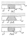
- Fig. 4 shows a second embodiment of a transport lock, in which the holding member consists of juxtaposed cams 20 and 21, between which the adjusting element 11 can be inserted in a form-fitting manner by lowering the container onto the loading surface 4 from above.
- FIG 5 shows a third embodiment, in which the holding member 9 has an undercut 22 and the adjusting element 11 inserts one into the undercut 22 fenden projection 23 has.
- Holding member and adjusting element are shown in a position in which the container has assumed the transport position. By undercut and protrusion, a positive connection between the holding member 9 and the adjusting element 11 is ensured, which can also secure a received container against tilting forces.
- FIG. 6 shows a plan view of a loading area 4 of a vehicle with a swap body attached, which is illustrated here by its bottom rails 10 and the fitting 7. With 24 in the area of the rear end face located on the container rolling elements are designated with which known swap bodies are equipped.
- a transport lock according to FIG. 4 is provided.
- Each adjustment element 11 is a projecting tab 25 attached laterally to a floor rail 10.
- FIG. 7 shows a top view of a detail of one of the transport locks corresponding to FIG. 6, the bottom rail again being designated by 10.
- the upper flange of the bottom rail 10 is visible.
- the web of the floor rail is indicated by the dash-dotted line.
- the two cams 20 and 21 of the holding member are simple blocks, it being visible how the adjusting element 11, which is designed as a tab 25, engages in a form-fitting manner between the two cams 20 and 21.
- FIG. 8 shows another embodiment in plan view corresponding to FIG. 7.
- the cams 20 'and 21' and the tab 25 ' are provided with undercuts here, so that a positive connection is possible in the transport position.
- the tab has an approximately dovetail shape.
- Fig. 9 a further embodiment of the mutual positive locking of the cams 21 ⁇ and 20 ⁇ with the tab 25 ⁇ is shown.
- a first cam 21 of each holding element 9 facing one end face of a vehicle loading surface 4 is flatter than the respectively interacting adjacent second cam 20 of the same holding element .
- An end face of a loading area is indicated by the arrow 26 in FIG. 1 and in FIG. 6.
- Fig. 4 is also shown by the dashed line 27 on the left cam 21 that the cam 21 can be approximately half-high.
- FIG. 10 shows a view corresponding to FIG. 6 in the direction of arrow 26, seen from the left.
- the same components are identified by the same reference numbers.
- Fig. 10 shows how the tab 25 is attached to the floor rails 10 and how the cams 21 and 20 are on the loading surface 4.
- the container 5 has assumed its transport position and is secured against further displacement by the tab 25 which engages between the two cams. Nevertheless, in this embodiment of the transport lock, the interchangeable container 5 can be lifted vertically upwards, for example with a lifting device, from the loading area 4.
- the container 5 can also be handled easily by means of an interchangeable device by first lifting the container 5 with the interchangeable device to such an extent that the tab 25 is lifted over the somewhat flatter cam 21, at the same time moving the interchangeable container on the loading surface 4 can be done.
Landscapes
- Engineering & Computer Science (AREA)
- Transportation (AREA)
- Mechanical Engineering (AREA)
- Handcart (AREA)
- Fittings On The Vehicle Exterior For Carrying Loads, And Devices For Holding Or Mounting Articles (AREA)
- Load-Engaging Elements For Cranes (AREA)
- Loading Or Unloading Of Vehicles (AREA)
- Financial Or Insurance-Related Operations Such As Payment And Settlement (AREA)
Abstract
Description
Die Erfindung betrifft eine Transportsicherung für Behälter, insbesondere Wechselbehälter, die mit einem Hebezeug, zum Beispiel einem Wechselgerät, auf der Ladefläche eines Transportfahrzeuges absetzbar sind.The invention relates to a transport lock for containers, in particular swap bodies, which can be placed on the loading surface of a transport vehicle using a lifting device, for example an exchangeable device.
Es ist bekannt, Wechselbehälter während ihres Transportes auf Fahrzeugen gegen Verrutschen und Kippen durch entsprechende Verriegelungseinrichtungen zu sichern. Die bekannten Verriegelungseinrichtungen umfassen zum Beispiel an der Unterseite des Behälters angeordnete waagerechte Stifte, die sich in am Fahrzeug angeordnete Augen einschieben, sobald der Behälter auf dem Fahrzeug seine für den Transport vorgesehene Endlage, die Transportlage, eingenommen hat. Bekannt sind außerdem betätigbare Verriegelungselemente, die aus um waagerechte Achsen, die in Längsrichtung des Fahrzeugs ausgerichtet sind, verschwenkbaren hakenförmigen Laschen bestehen, die an der Behälterunterseite befindliche Flansche von Verstärkungsprofilen, Bodenschienen oder dergleichen Vorsprüngen übergreifen können und dadurch den Behälter auch gegen Abheben von der Ladefläche sichern.It is known to secure swap bodies during transportation on vehicles against slipping and tipping by means of appropriate locking devices. The known locking devices include, for example, horizontal pins arranged on the underside of the container, which slide into eyes arranged on the vehicle as soon as the container has assumed its end position intended for transport, the transport position, on the vehicle. Also known are actuable locking elements which consist of hook-shaped tabs which can be pivoted about horizontal axes which are aligned in the longitudinal direction of the vehicle and which can overlap the flanges of reinforcing profiles, floor rails or similar projections located on the underside of the container and thereby prevent the container from being lifted off the loading area to back up.
Es sind auch Kombinationen der vorbeschriebenen Einrichtungen möglich, um eine Transportsicherung eines Wechselbehälters zu gewährleisten.Combinations of the devices described above are also possible in order to ensure that an interchangeable container is secured in transit.
Die bekannten Systeme zur Transportsicherung von Wechselbehältern haben den Nachteil, daß sie auf die Verwendung in Verbindung mit einem an sich bekannten Wechselgerät speziell angepaßt sind. In der Praxis kann es durchaus vorkommen, daß Wechselbehälter nicht mit einem Wechselgerät sondern mit einem anderen Hebezeug, zum Beispiel einem üblichen Kran, auf Transportfahrzeuge aufgesetzt bzw. davon abgenommen werden. Denkbar ist dies bei Eisenbahnwagen, Lastwagenanhängern, Wasserfahrzeugen und dergleichen, wobei auch insbesondere sogenannte Ladekräne zum Einsatz kommen können, mit denen Fahrzeuge häufig ausgerüstet sind, um das Auf- und Abladen z.B. von Stückgut zu erleichtern.The known systems for securing transport of swap bodies have the disadvantage that they are specially adapted for use in connection with a swap device known per se. In practice, it may well happen that swap bodies are placed on or removed from transport vehicles not with an exchangeable device but with another lifting device, for example a conventional crane. This is conceivable for railway wagons, truck trailers, water vehicles and the like, whereby so-called loading cranes can also be used in particular, with which vehicles are often equipped to load and unload e.g. to facilitate general cargo.
Die bekannten Transportsicherungen verhindern aber gerade eine Bewegung der Behälter in einer Richtung lotrecht zur Ladefläche, auf der die Behälter stehen bzw. abgesetzt werden sollen, so daß ein mit einem Wechselgerät aufgeladener Behälter z.B. nicht mit einem anderen Hebezeug, einem Kran, abgeladen werden kann.However, the known transport locks prevent the containers from moving in a direction perpendicular to the loading surface on which the containers are to be placed or are to be placed, so that a container charged with an exchange device e.g. cannot be unloaded with another hoist, a crane.
Der Erfindung liegt die Aufgabe zugrunde, eine Transportsicherung so auszubilden, daß sie ihre Funktion sowohl bei einem Umschlag der Behälter mit an sich bekannten Wechselgeräten als auch mit anderen Hebezeugen, wie zum Beispiel einem üblichen Kran, erfüllen können.The invention has for its object to provide a transport lock so that it can perform its function both when handling the container with known exchange devices as well as with other hoists, such as a conventional crane.
Diese Aufgabe ist erfindungsgemäß dadurch gelöst, daß an der Unterseite des Behälters in der Ebene seiner Auflagebereiche auf der Ladefläche Justierelemente angeordnet sind, daß an der Ladefläche Halteorgane angeordnet sind und daß an jeweils einem Halteorgan ein zugeordnetes Justierelement in der Transportlage des Behälters gehalten ist.This object is achieved in that adjusting elements are arranged on the underside of the container in the plane of its support areas on the loading surface, that holding members are arranged on the loading surface and that an associated adjusting element is held in the transport position of the container on each holding element.
Die Justierelemente legen die Position fest, die der Be hälter auf der Ladefläche eines Fahrzeuges einnehmen soll. Justierelemente und Halteorgane können deshalb als konstruktiv einfache Anschläge ausgebildet werden, die sich aneinanderlegen, sobald der Behälter seine endgültige Transportstellung auf der Ladefläche eingenommen hat, wobei es keine Rolle spielt, ob er diese Transportstellung durch Einwirkung eines Wechselgerätes erreicht oder durch Einwirkung eines anderen Hebezeugs, beispielsweise eines üblichen Krans. Durch entsprechende Ausbildung von Justierelement und Halteorgan ist gewährleistet, daß jedes Justierelement am Halteorgan in der vorgesehenen Transportlage des Behälters gehalten wird, wodurch die gewünschte Transportsicherung gewährleistet ist.The adjustment elements determine the position that the loading container on the back of a vehicle. Adjusting elements and holding members can therefore be designed as structurally simple stops which abut each other as soon as the container has reached its final transport position on the loading surface, it does not matter whether it reaches this transport position by the action of an exchange device or by the action of another lifting device, for example a common crane. Appropriate training of the adjusting element and the holding element ensures that each adjusting element is held on the holding element in the intended transport position of the container, thereby ensuring the desired transport security.
Dies kann zum Beispiel dadurch erreicht werden, daß Justierelement und Halteorgan als gegenseitig in Eingriff bringbare Formschlußelemente ausgebildet sind. Diese Formschlußelemente sind so ausgerichtet, daß ein Justierelement am Behälter in das zugeordnete Halteorgan an der Ladefläche des Fahrzeugs von oben frei beweglich eingeführt bzw. herausgeführt werden kann, sobald der Behälter auf die Ladefläche abgesenkt oder davon abgehoben wird. Dabei ist wieder unerheblich, ob das Absenken oder Anheben mittels eines Krans oder eines Wechselgeräts erfolgt. Da Justierelement und Halteorgan gleichzeitig als die Transportlage des Behälters festlegende Anschläge dienen, ist ein auf einer Ladefläche eines Fahrzeugs abgesetzter Behälter gegen Brems- und Beschleunigungskräfte gesichert, die in Längsrichtung des Fahrzeugs während des Transports wirken. Durch die Ausbildung als Formschlußelemente kann gleichzeitig auch eine Sicherung gegen quer zur Fahrzeuglängsachse bzw. Behälterlängsachse wirkende Kräfte erreicht werden. Dies ist dadurch möglich, daß jedes Halteorgan wenigstens eine Hinterschneidung aufweist und daß das Justierelement mindestens einen in die Hinterschneidung eingreifenden Vorsprung hat, wodurch der Formschluß gewährleistet ist, sobald der Behälter auf der Ladefläche steht. Dabei kann der Formschluß z.B. schwalbenschwanzförmig oder auch keilförmig sein.This can be achieved, for example, in that the adjusting element and the holding member are designed as interlocking elements that can be brought into engagement with one another. These form-locking elements are aligned so that an adjusting element on the container can be freely moved in and out of the associated holding member on the loading surface of the vehicle from above as soon as the container is lowered onto the loading surface or lifted off it. It is again irrelevant whether the lowering or lifting takes place by means of a crane or an exchange device. Since the adjusting element and the holding member serve at the same time as stops defining the transport position of the container, a container placed on a loading surface of a vehicle is secured against braking and acceleration forces which act in the longitudinal direction of the vehicle during transport. Due to the design as form-fitting elements, protection against forces acting transversely to the vehicle longitudinal axis or the container longitudinal axis can be achieved at the same time. This is possible in that each holding member has at least one undercut and in that the adjusting element has at least one projection which engages in the undercut, as a result of which the positive engagement is guaranteed as soon as the container is on the loading surface. The form fit can be dovetail-shaped or wedge-shaped, for example.
Jedes Halteorgan besteht vorzugsweise aus nebeneinander stehenden Nocken, wobei jedes Justierelement ein zwischen die Nocken setzbares vorspringendes Teil ist. Das Justierelement greift somit zwischen jeweils zwei Nocken eines Halteorgans, sobald der Behälter auf der Ladefläche steht, mit dem Vorteil, daß eine Sicherung des Behälters gegen Längs- und Querkräfte während des Transports gegeben ist.Each holding member preferably consists of juxtaposed cams, each adjusting element being a projecting part which can be placed between the cams. The adjusting element thus engages between two cams of a holding member as soon as the container is on the loading surface, with the advantage that the container is secured against longitudinal and transverse forces during transport.
Damit die für das Auf- und Absetzen mit einem Wechselgerät notwendige Verschiebebewegung des Behälters auf der Ladefläche durch die nebeneinanderstehenden Nocken des Halteorgans nicht behindert wird, ist nach einer Weiterbildung vorgesehen, daß ein jeweils einer Stirnseite einer Fahrzeugladefläche zugekehrter erster Nocken des Halteorgans flacher als der jeweils damit zusammenwirkende benachbarte zweite Nocken des gleichen Halteorgans ist. Dadurch ist es möglich, einen Behälter mit einem Wechselgerät auf der Ladefläche zu bewegen. Das Justierelement kann bei Schiebebewegungen des Behälters ohne Behinderung über den flachen ersten Nocken geschoben werden, weil das Wechselgerät den Behälter üblicherweise auch leicht angehoben verschieben kann. Sobald das Justierelement an den zweiten höheren Nocken des gleichen Halteelementes angeschlagen ist, ist die endgültige Lage des Behälters auf der Ladefläche erreicht und kann sich der Behälter absenken, so daß das Justierelement nunmehr gesichert zwischen den beiden Nocken liegt.So that the shifting movement of the container on the loading surface necessary for mounting and dismounting with an interchangeable device is not hindered by the cams of the holding member standing side by side, according to a further development it is provided that a first cam of the holding member facing one end face of a vehicle loading surface is flatter than the one in each case cooperating adjacent second cam of the same holding member. This makes it possible to move a container with a changer on the loading area. The adjusting element can be slid over the flat first cam when the container is being moved, since the changing device can usually also move the container slightly raised. As soon as the adjusting element is struck on the second higher cam of the same holding element, the final position of the container on the loading surface is reached and the container can lower, so that the adjusting element is now securely located between the two cams.
Vorzugsweise ist jedes Justierelement eine an eine vorstehende Bodenschiene seitlich angesetzte, parallel zum Boden des Behälters ausgerichtete Lasche. Das freie Ende dieser Lasche kann schwalbenschwanzförmig oder keilförmig ausgebildet sein, um den bereits erwähnten Formschluß mit den entsprechend ausgebildeten Nocken zu bewirken.Each adjustment element is preferably a tab which is laterally attached to a projecting bottom rail and is aligned parallel to the bottom of the container. The free end this tab can be dovetailed or wedge-shaped in order to bring about the already mentioned positive engagement with the correspondingly designed cams.
Jeder Nocken ist vorzugsweise ein auf der Ladefläche befestigter Klotz. Solche Klötze können auch direkt an der Kippbrücke eines Wechselgerätes angeordnet werden, mit dem zum Beispiel ein Kraftfahrzeug ausgerüstet ist.Each cam is preferably a block attached to the bed. Such blocks can also be arranged directly on the tilting bridge of a changing device with which, for example, a motor vehicle is equipped.
Vorzugsweise sind für jeden auf einer Ladefläche stehenden Behälter jeweils vier Justierelemente und Halteorgane vorgesehen.Four adjusting elements and holding members are preferably provided for each container standing on a loading surface.
Es ist jedoch auch möglich, für jeden Behälter zwei im Bereich einer seiner Stirnseiten sichernde Justierelemente und Halteorgane vorzusehen, wobei die jeweils andere Stirnseite mit einer an sich bekannten betätigbaren Verriegelung gesichert sein kann. Allerdings muß die Verriegelung gelöst werden, sobald der Behälter von der Ladefläche abgenommen oder wieder aufgesetzt werden soll. Dies kann zum Beispiel durch hydraulische, pneumatische aber auch mechanische Betätigung erfolgen. Jede Verriegelung kann zum Beispiel eine in zugeordnete Aufnahmen am Behälter einsetzbare Klammerbacke umfassen, wobei die Klammerbacke um entsprechende Achsen gelenkig bewegbar ist, und die Bewegung durch Hydraulik, Pneumatik oder Mechanik erzeugt wird.However, it is also possible to provide two adjusting elements and holding members securing each container in the area of one of its end faces, the other end face in each case being secured with a lock which is known per se and which can be actuated. However, the lock must be released as soon as the container is to be removed from the loading area or replaced. This can be done for example by hydraulic, pneumatic but also mechanical actuation. Each lock can, for example, comprise a clamp jaw which can be inserted into assigned receptacles on the container, the clamp jaw being articulated about corresponding axes, and the movement being generated by hydraulics, pneumatics or mechanics.
Ausführungsbeispiele der Erfindung, aus denen sich weitere erfinderische Merkmale ergeben, sind in der Zeichnung dargestellt. Es zeigen:
- Fig. 1 die schematische Seitenansicht eines Fahrzeuges mit aufgeladenem Wechselbehälter,
- Fig. 2 ein erstes Ausführungsbeispiel einer Transportsicherung,
- Fig. 3 einen Teil der Transportsicherung gemäß Fig. 2 in der Transportstellung,
- Fig. 4 eine zweite Ausführungsform der Transportsicherung,
- Fig. 5 eine dritte Ausführungsform,
- Fig. 6 eine schematische Draufsicht auf eine Ladefläche eines Fahrzeugs mit aufgeladenem Behälter, von dem lediglich die an der Transportsicherung beteiligten Bauteile dargestellt sind,
- Fig. 7 ein Detail einer Transportsicherung in einer Draufsicht entsprechend Fig. 6,
- Fig. 8 eine weitere Ausführungsform einer Transportsicherung in einer Ansicht entsprechend Fig. 7,
- Fig. 9 eine andere Ausführungsform einer Transportsicherung in einer Ansicht entsprechend Fig. 7 und
- Fig. 10 eine Ansicht eines Fahrzeugs mit auf der Ladefläche aufgenommenem Behälter entsprechend Fig. 6, von der linken Stirnseite des Fahrzeugs aus gesehen.
- 1 is a schematic side view of a vehicle with a charged swap body,
- 2 shows a first embodiment of a transport lock,
- 3 shows a part of the transport lock according to FIG. 2 in the transport position,
- 4 shows a second embodiment of the transport lock,
- 5 shows a third embodiment,
- 6 shows a schematic plan view of a loading area of a vehicle with a loaded container, of which only the components involved in the transportation lock are shown,
- 7 shows a detail of a transport lock in a top view corresponding to FIG. 6,
- 8 shows a further embodiment of a transport lock in a view corresponding to FIG. 7,
- Fig. 9 shows another embodiment of a transport lock in a view corresponding to Fig. 7 and
- 10 is a view of a vehicle with the container received on the loading area corresponding to FIG. 6, seen from the left end of the vehicle.
In Fig. 1 ist ein Lastkraftwagen in der Seitenansicht dargestellt, dessen Chassis 1 mit einem Wechselgerät ausgerüstet ist, bei dem die mittels eines Arbeitszylinders 2 um einen hinteren Drehpunkt 3 verschwenkbare Kippbrücke als Ladefläche 4 dient, auf der ein an sich bekannter Wechselbehälter 5 aufgenommen ist. Das Wechselgerät ist ein sogenanntes Hakengerät, das mit seinem Haken 6 in einen Beschlag 7 am Behälter eingreifen kann. Der Haken 6 ist in Richtung des Pfeiles 8 relativ zur Kippbrücke des Wechselgerätes in Längsrichtung des Fahrzeugchassis 1 beweglich. An der als Ladefläche 4 dienenden Kippbrücke des Wechselgerätes befindet sich ein Halteorgan 9. Der Wechselbehälter 5 hat an seiner Unterseite verstärkende Bodenschienen 10. Mit den Bodenschienen gleitet der Wechselbehälter auf der als Ladefläche 4 dienenden Kippbrücke des Wechselge rätes. An der Unterseite des Wechselbehälters, vorzugsweise an seinen Bodenschienen 10, befinden sich Justierelemente 11.In Fig. 1, a truck is shown in side view, the
Im hinteren Bereich ist an der als Ladefläche 4 dienenden Kippbrücke eine an sich bekannte Verriegelung 12 angeordnet, die z.B. als umlegbare Klammer ausgebildet sein kann, die hinter einen Flansch der Bodenschiene 10 greift.In the rear area, a
Während des Aufnehmens des Wechselbehälters 5 erfolgt ein Verschieben des Wechselbehälters mit dem Haken 6 auf der als Ladefläche 4 dienenden Kippbrücke des Wechselgerätes nach links, bis das Justierelement 11, welches am Wechselbehälter angeordnet ist, an das Halteorgan 9, welches an der Kippbrücke bzw. der Ladefläche 4 befestigt ist, anschlägt. Der Wechselbehälter hat dann seine Transportlage eingenommen. Gleichzeitig ist er durch gegenseitiges Anschlagen von Halteorgan und Justierelement gegen Verrutschen in Richtung des Doppelpfeils 13 gesichert. Zur zusätzlichen Sicherung wird noch die an sich bekannte Verriegelung 12 in Verrastungsstellung gebracht.While the interchangeable container 5 is being picked up, the interchangeable container with the
Der Behälter kann nach Öffnen der Verriegelung sowohl mit dem hier dargestellten Wechselgerät abgesetzt werden. Dennoch ist es aufgrund der besonderen Bauart der Transportsicherung möglich, den hier in seiner Transportlage dargestellten Behälter auch mit einem anderen Hebezeug, beispielsweise einem üblichen Kran, lotrecht nach oben in Richtung des Pfeils 14 vom Fahrzeug abzuheben oder auch abzusetzen.After opening the lock, the container can be placed with the change device shown here. Nevertheless, due to the special design of the transport lock, it is also possible to lift the container shown here in its transport position with another hoist, for example a conventional crane, vertically upwards in the direction of
In Fig. 2 ist eine Bodenschiene 10 eines hier nicht weiter sichtbaren Wechselbehälters teilweise in der Seitenansicht dargestellt. Mit 4 ist eine Ladefläche bezeichnet, die ebenfalls durch ein Profil gebildet sein kann. An die sem die Ladefläche 4 bildenden Profil ist ein Halteorgan 9 so angeordnet, daß es gegen die Unterseite des hier nicht sichtbaren Behälters vorsteht, wobei die Unterseite durch den oberen Flansch 15 der Bodenschiene 10 angegeben wird, der hier als einfacher Strich gezeichnet ist.In Fig. 2, a
Das Justierelement 11 ist an der Bodenschiene 10 angeordnet und steht aus der Zeichnungsebene heraus vor, so daß bei Verschieben der Bodenschiene 10 bzw. des ganzen Wechselbehälters in Richtung des Doppelpfeiles 13, Justierelement 11 und Halteorgan 9 gegeneinander geschoben werden oder sich voneinander entfernen.The adjusting
Mit 12 ist wieder eine Verriegelung schematisch angedeutet, die hier als um eine Klappachse 16 an der Ladefläche angelenkte Klammerbacke 17 ausgebildet ist, die einen unteren Flansch 18 der Bodenschiene 10 umgreifen bzw. freigeben kann, wenn eine Verschwenkung in Richtung des Kreisbogenpfeils 19 mit Hilfe geeigneter Betätigungselemente erfolgt, die hier nicht weiter dargestellt sind.With 12, a lock is again indicated schematically, which is designed here as a
Fig. 3 zeigt eine Ansicht entsprechend Fig. 2, wobei Halteorgan 9 und Justierelement 11 durch Verschieben des Behälters relativ zur Ladefläche 4 nach links so weit verschoben sind, daß nahezu ein Anschlag gegeben ist bzw. der Behälter seine Transportlage nahezu eingenommen hat.Fig. 3 shows a view corresponding to Fig. 2, wherein the holding
Fig. 4 zeigt eine zweite Ausführungsform einer Transportsicherung, bei der das Halteorgan aus nebeneinander stehenden Nocken 20 und 21 besteht, zwischen die das Justierelement 11 formschlüssig einsetzbar ist, indem der Behälter von oben auf die Ladefläche 4 abgesenkt wird.Fig. 4 shows a second embodiment of a transport lock, in which the holding member consists of
Fig. 5 zeigt eine dritte Ausführungsform, bei der das Halteorgan 9 eine Hinterschneidung 22 aufweist und das Justierelement 11 einen in die Hinterschneidung 22 eingrei fenden Vorsprung 23 besitzt. Halteorgan und Justierelement sind in einer Position dargestellt, bei welcher der Behälter die Transportlage eingenommen hat. Durch Hinterschneidung und Vorsprung ist eine Formschlußverbindung zwischen Halteorgan 9 und Justierelement 11 gewährleistet, die einen aufgenommenen Behälter auch gegen Kippkräfte sichern kann.5 shows a third embodiment, in which the holding
Es ist möglich, einen Behälter im vorderen Bereich unten mit einer Transportsicherung entsprechend Fig. 3 auszubilden, wobei die in Fig. 1 und Fig. 2 sichtbare Verriegelung 12 durch eine Transportsicherung entsprechend Fig. 5 ersetzt werden kann.It is possible to design a container in the front area at the bottom with a transport lock according to FIG. 3, the
Fig. 6 zeigt eine Draufsicht auf eine Ladefläche 4 eines Fahrzeugs mit aufgesetztem Wechselbehälter, der hier durch seine Bodenschienen 10 sowie den Beschlag 7 verdeutlicht ist. Mit 24 sind im Bereich der hinteren Stirnseite am Behälter befindliche Rollemente bezeichnet, mit denen an sich bekannte Wechselbehälter ausgerüstet sind.6 shows a plan view of a
Bei diesem Ausführungsbeispiel ist eine Transportsicherung entsprechend Fig. 4 vorgesehen. Auf der Ladefläche befinden sich vier Halteorgane, die aus jeweils nebeneinander stehenden Nocken 20 und 21 bestehen. Die Bodenschienen 10, die als parallel zueinander verlaufende Doppel-T-Profile ausgebildet sind, weisen vier Justierelemente 11 auf. Jedes Justierelement 11 ist eine an eine Bodenschiene 10 seitlich angesetzte vorstehende Lasche 25.In this embodiment, a transport lock according to FIG. 4 is provided. There are four holding members on the loading area, each of which consists of
Fig. 7 zeigt eine Detailansicht einer der Transportsicherungen entsprechend Fig. 6 in der Draufsicht, wobei die Bodenschiene wieder mit 10 bezeichnet ist. In Fig. 7 ist der obere Flansch der Bodenschiene 10 sichtbar. Der Steg der Bodenschiene ist durch die strichpunktierte Linie angedeutet. Die beiden Nocken 20 und 21 des Halteorgans sind einfache Klötze, wobei sichtbar ist, wie das als Lasche 25 ausgebildete Justierelement 11 zwischen die beiden Nocken 20 und 21 formschlüssig eingreift.FIG. 7 shows a top view of a detail of one of the transport locks corresponding to FIG. 6, the bottom rail again being designated by 10. In Fig. 7 the upper flange of the
Fig. 8 zeigt eine andere Ausführungsform in der Draufsicht entsprechend Fig. 7.FIG. 8 shows another embodiment in plan view corresponding to FIG. 7.
Die Nocken 20′ und 21′ sowie die Lasche 25′ sind hier mit Hinterschneidungen versehen, so daß in der Transportlage eine formschlüssige Verbindung möglich ist. Bei dieser Ausführungsform weist die Lasche etwa schwalbenschwanzförmigen Umriß auf. In Fig. 9 ist eine weitere Ausführungsform des gegenseitigen Formschlusses der Nocken 21˝ und 20˝ mit der Lasche 25˝ dargestellt.The cams 20 'and 21' and the tab 25 'are provided with undercuts here, so that a positive connection is possible in the transport position. In this embodiment, the tab has an approximately dovetail shape. In Fig. 9 a further embodiment of the mutual positive locking of the
Zwei nebeneinander befindliche Nocken, zwischen die eine Lasche eingreift, sichern den Behälter auf der Ladefläche optimal gegen Brems- und Beschleunigungskräfte sowie gegen Querkräfte bei Kurvenfahrten.Two cams next to each other, between which a tab engages, optimally secure the container on the loading surface against braking and acceleration forces as well as against lateral forces when cornering.
Bei Verschiebebewegungen des Behälters auf der Ladefläche zwecks Aufnehmens oder Absetzens mit einem Wechselgerät können die im Verschiebeweg des in seine Transportlage zu verschiebenden Behälters zunächst vorstehenden Nocken der Halteorgane hinderlich sein. Um zu vermeiden, daß bereits die der Verschiebebewegung zugekehrten Flächen der Nocken eine weitere Verschiebebewegung verhindern, ist vorgesehen, daß ein jeweils einer Stirnseite einer Fahrzeugladefläche 4 zugekehrter erster Nocken 21 jedes Halteorgans 9 flacher als der jeweils damit zusammenwirkende benachbarte zweite Nocken 20 des gleichen Halteorgans ist. In Fig. 1 und in Fig. 6 ist eine Stirnseite einer Ladefläche durch den Pfeil 26 angedeutet. In Fig. 4 ist darüberhinaus durch die gestrichelte Linie 27 am linken Nocken 21 gezeigt, daß der Nocken 21 etwa halbhoch sein kann.When the container is displaced on the loading surface for picking up or setting down with an interchangeable device, the cams of the holding members initially protruding in the displacement of the container to be moved into its transport position can be a hindrance. In order to avoid that the surfaces of the cams facing the displacement movement prevent a further displacement movement, it is provided that a
Fig. 10 zeigt eine Ansicht entsprechend Fig. 6 in Richtung des Pfeils 26, von links gesehen. Gleiche Bauteile sind mit gleichen Bezugszahlen bezeichnet. Fig. 10 läßt erkennen, wie die Lasche 25 an den Bodenschienen 10 angebracht ist und wie die Nocken 21 und 20 auf der Ladefläche 4 stehen. Der Behälter 5 hat seine Transportlage eingenommen und ist durch die Lasche 25, die zwischen die beiden Nocken greift, gegen weiteres Verschieben gesichert. Dennoch kann bei dieser Ausführungsform der Transportsicherung der Wechselbehälter 5 lotrecht nach oben, beispielsweise mit einem Hebezeug, von der Ladefläche 4 abgehoben werden. Auch der Umschlag des Behälters 5 mittels eines Wechselgerätes ist ohne weiteres möglich, indem der Behälter 5 mit dem Wechselgerät zunächst so weit angehoben wird, daß die Lasche 25 über den etwas flacheren Nocken 21 hinweggehoben wird, wobei gleichzeitig ein Verschieben des Wechselbehälters auf der Ladefläche 4 erfolgen kann.FIG. 10 shows a view corresponding to FIG. 6 in the direction of
Claims (13)
dadurch gekennzeichnet,
daß an der Unterseite des Behälters (5) in der Ebene seiner Auflagebereiche auf der Ladefläche (4) Justierelemente (11) angeordnet sind, daß an der Ladefläche (4) Halteorgane (9) angeordnet sind und daß an jeweils einem Halteorgan (9) ein zugeordnetes Justierelement (11) in der Transportlage des Behälters (5) gehalten ist.1. Transport securing device for containers, in particular swap bodies, which can be placed on the loading surface of a transport vehicle using a lifting device, for example an exchangeable device,
characterized,
that on the underside of the container (5) in the plane of its support areas on the loading surface (4) adjusting elements (11) are arranged, that on the loading surface (4) holding members (9) are arranged and that in each case a holding member (9) assigned adjustment element (11) is held in the transport position of the container (5).
Priority Applications (1)
| Application Number | Priority Date | Filing Date | Title |
|---|---|---|---|
| AT88110520T ATE71031T1 (en) | 1987-07-10 | 1988-07-01 | TRANSPORT SECURITY FOR CONTAINERS, ESPECIALLY SWAP CONTAINERS. |
Applications Claiming Priority (2)
| Application Number | Priority Date | Filing Date | Title |
|---|---|---|---|
| DE8709539U DE8709539U1 (en) | 1987-07-10 | 1987-07-10 | |
| DE8709539U | 1987-07-10 |
Publications (2)
| Publication Number | Publication Date |
|---|---|
| EP0298384A1 true EP0298384A1 (en) | 1989-01-11 |
| EP0298384B1 EP0298384B1 (en) | 1992-01-02 |
Family
ID=6809952
Family Applications (1)
| Application Number | Title | Priority Date | Filing Date |
|---|---|---|---|
| EP88110520A Expired - Lifetime EP0298384B1 (en) | 1987-07-10 | 1988-07-01 | Securing of container during transport, especially removable container |
Country Status (5)
| Country | Link |
|---|---|
| EP (1) | EP0298384B1 (en) |
| AT (1) | ATE71031T1 (en) |
| DE (2) | DE8709539U1 (en) |
| ES (1) | ES2029495T3 (en) |
| WO (1) | WO1993013960A1 (en) |
Cited By (6)
| Publication number | Priority date | Publication date | Assignee | Title |
|---|---|---|---|---|
| DE8903150U1 (en) * | 1989-03-14 | 1989-08-24 | Edelhoff Polytechnik Gmbh & Co, 5860 Iserlohn, De | |
| EP0529209A1 (en) * | 1991-08-29 | 1993-03-03 | EDELHOFF POLYTECHNIK GMBH & CO. | Securing device for transport |
| EP0560313A2 (en) * | 1992-03-13 | 1993-09-15 | ROLFO S.p.A. | A road vehicle with a removable load-carrying superstructure, particularly for transporting motor vehicles |
| EP0626298A1 (en) * | 1993-05-27 | 1994-11-30 | Linke-Hofmann-Busch GmbH | Tank-wagon logistical system |
| WO2002047940A3 (en) * | 2000-12-12 | 2002-08-15 | Hueffermann Fahrzeugtech Gmbh | Vehicle for transporting an interchangeable container |
| DE102019113055A1 (en) * | 2019-05-17 | 2020-11-19 | Deutsche Bahn Ag | Securing system for securing a load receiving unit against a rail vehicle underframe |
Citations (4)
| Publication number | Priority date | Publication date | Assignee | Title |
|---|---|---|---|---|
| US2251839A (en) * | 1940-04-29 | 1941-08-05 | Eugene J Dondlinger | Removable truck body |
| US2273854A (en) * | 1940-04-15 | 1942-02-24 | Motor Terminals Inc | Device for positioning containers on vehicles |
| US3144838A (en) * | 1961-06-07 | 1964-08-18 | Pullman Inc | Container support device for a railway car |
| DE1456673A1 (en) * | 1966-04-02 | 1969-03-06 | Maschf Augsburg Nuernberg Ag | Device for centering and lashing large-capacity containers on vehicles, in particular rail vehicles |
-
1987
- 1987-07-10 DE DE8709539U patent/DE8709539U1/de not_active Expired
-
1988
- 1988-07-01 ES ES198888110520T patent/ES2029495T3/en not_active Expired - Lifetime
- 1988-07-01 EP EP88110520A patent/EP0298384B1/en not_active Expired - Lifetime
- 1988-07-01 DE DE8888110520T patent/DE3867340D1/en not_active Expired - Fee Related
- 1988-07-01 WO PCT/DE1988/000407 patent/WO1993013960A1/en unknown
- 1988-07-01 AT AT88110520T patent/ATE71031T1/en not_active IP Right Cessation
Patent Citations (4)
| Publication number | Priority date | Publication date | Assignee | Title |
|---|---|---|---|---|
| US2273854A (en) * | 1940-04-15 | 1942-02-24 | Motor Terminals Inc | Device for positioning containers on vehicles |
| US2251839A (en) * | 1940-04-29 | 1941-08-05 | Eugene J Dondlinger | Removable truck body |
| US3144838A (en) * | 1961-06-07 | 1964-08-18 | Pullman Inc | Container support device for a railway car |
| DE1456673A1 (en) * | 1966-04-02 | 1969-03-06 | Maschf Augsburg Nuernberg Ag | Device for centering and lashing large-capacity containers on vehicles, in particular rail vehicles |
Cited By (8)
| Publication number | Priority date | Publication date | Assignee | Title |
|---|---|---|---|---|
| DE8903150U1 (en) * | 1989-03-14 | 1989-08-24 | Edelhoff Polytechnik Gmbh & Co, 5860 Iserlohn, De | |
| EP0529209A1 (en) * | 1991-08-29 | 1993-03-03 | EDELHOFF POLYTECHNIK GMBH & CO. | Securing device for transport |
| EP0560313A2 (en) * | 1992-03-13 | 1993-09-15 | ROLFO S.p.A. | A road vehicle with a removable load-carrying superstructure, particularly for transporting motor vehicles |
| EP0560313A3 (en) * | 1992-03-13 | 1994-04-20 | Rolfo Spa | |
| EP0626298A1 (en) * | 1993-05-27 | 1994-11-30 | Linke-Hofmann-Busch GmbH | Tank-wagon logistical system |
| WO2002047940A3 (en) * | 2000-12-12 | 2002-08-15 | Hueffermann Fahrzeugtech Gmbh | Vehicle for transporting an interchangeable container |
| DE102019113055A1 (en) * | 2019-05-17 | 2020-11-19 | Deutsche Bahn Ag | Securing system for securing a load receiving unit against a rail vehicle underframe |
| DE102019113055B4 (en) * | 2019-05-17 | 2021-03-11 | Deutsche Bahn Ag | Securing system for securing a load receiving unit against a rail vehicle underframe |
Also Published As
| Publication number | Publication date |
|---|---|
| DE8709539U1 (en) | 1987-10-29 |
| ES2029495T3 (en) | 1992-08-16 |
| WO1993013960A1 (en) | 1993-07-22 |
| EP0298384B1 (en) | 1992-01-02 |
| ATE71031T1 (en) | 1992-01-15 |
| DE3867340D1 (en) | 1992-02-13 |
Similar Documents
| Publication | Publication Date | Title |
|---|---|---|
| EP2185382B1 (en) | Apparatus for securing a container on a platform of a transport vehicle | |
| EP1661755B1 (en) | Load carrying vehicle, in particular skip transport vehicle | |
| DE2254886A1 (en) | LIFT TRUCK WITH DETACHABLE FORK | |
| EP0298382A1 (en) | Container for storage and transportation of especially bulk material, such as rubble, garbage, industrial waste and the like | |
| EP0298384B1 (en) | Securing of container during transport, especially removable container | |
| DE102015216998A1 (en) | Locking device for securing and locking a container and load transport vehicle | |
| DE2755223A1 (en) | EQUIPMENT FOR TRANSPORTING GOODS | |
| DE8528821U1 (en) | Single axle trailer | |
| EP0636080A1 (en) | Lifting frame | |
| EP0438998B1 (en) | Transportation vehicle, in particular low floor vehicle, as well as method of loading and unloading the same | |
| EP2574180B1 (en) | Transport means with a lifting platform and pushing element | |
| EP0298381B1 (en) | Box-shaped open top transport container | |
| DE2716338A1 (en) | Load securing clamps for lorry - using servo rams to press retaining bars against sides of load | |
| EP0639527A1 (en) | Loading frame with movable coupling-elements, particularly twist-locks | |
| EP1688300B1 (en) | Device for loading and unloading a platform | |
| DE3514525A1 (en) | METHOD AND ACCESSORIES FOR UNLOADING FREIGHT FROM A CONTAINER | |
| WO1998038115A1 (en) | Supporting device for containers or the like | |
| DE4336314C1 (en) | Carrying device | |
| DE202021004133U1 (en) | Floor conveyor for transporting containers on a supporting frame | |
| AT402059B (en) | Load gripping and carrying device on a crane for offloading containers, especially onto railbound or road vehicles | |
| EP1413477B1 (en) | Method and device for changing skips | |
| WO2001079081A1 (en) | Locking mechanism for containers, especially transport boxes | |
| EP0921970A1 (en) | Device for securing an object on a vehicle | |
| DE19526026C1 (en) | Device for fixing load container, esp. logistic box, on vehicle under-frame | |
| DE102017009175A1 (en) | Locking device for securing and locking a container |
Legal Events
| Date | Code | Title | Description |
|---|---|---|---|
| PUAI | Public reference made under article 153(3) epc to a published international application that has entered the european phase |
Free format text: ORIGINAL CODE: 0009012 |
|
| AK | Designated contracting states |
Kind code of ref document: A1 Designated state(s): AT BE CH DE ES FR GB IT LI LU NL SE |
|
| 17P | Request for examination filed |
Effective date: 19890526 |
|
| RAP1 | Party data changed (applicant data changed or rights of an application transferred) |
Owner name: EDELHOFF M.S.T.S. GMBH |
|
| 17Q | First examination report despatched |
Effective date: 19900904 |
|
| GRAA | (expected) grant |
Free format text: ORIGINAL CODE: 0009210 |
|
| AK | Designated contracting states |
Kind code of ref document: B1 Designated state(s): AT BE CH DE ES FR GB IT LI LU NL SE |
|
| REF | Corresponds to: |
Ref document number: 71031 Country of ref document: AT Date of ref document: 19920115 Kind code of ref document: T |
|
| REF | Corresponds to: |
Ref document number: 3867340 Country of ref document: DE Date of ref document: 19920213 |
|
| ITF | It: translation for a ep patent filed |
Owner name: INTERPATENT ST.TECN. BREV. |
|
| ET | Fr: translation filed | ||
| GBT | Gb: translation of ep patent filed (gb section 77(6)(a)/1977) | ||
| REG | Reference to a national code |
Ref country code: ES Ref legal event code: FG2A Ref document number: 2029495 Country of ref document: ES Kind code of ref document: T3 |
|
| PLBE | No opposition filed within time limit |
Free format text: ORIGINAL CODE: 0009261 |
|
| STAA | Information on the status of an ep patent application or granted ep patent |
Free format text: STATUS: NO OPPOSITION FILED WITHIN TIME LIMIT |
|
| 26N | No opposition filed | ||
| PGFP | Annual fee paid to national office [announced via postgrant information from national office to epo] |
Ref country code: CH Payment date: 19940726 Year of fee payment: 7 |
|
| PGFP | Annual fee paid to national office [announced via postgrant information from national office to epo] |
Ref country code: SE Payment date: 19940731 Year of fee payment: 7 Ref country code: LU Payment date: 19940731 Year of fee payment: 7 |
|
| EPTA | Lu: last paid annual fee | ||
| EAL | Se: european patent in force in sweden |
Ref document number: 88110520.9 |
|
| PG25 | Lapsed in a contracting state [announced via postgrant information from national office to epo] |
Ref country code: LU Free format text: LAPSE BECAUSE OF NON-PAYMENT OF DUE FEES Effective date: 19950701 |
|
| PG25 | Lapsed in a contracting state [announced via postgrant information from national office to epo] |
Ref country code: SE Effective date: 19950702 |
|
| PG25 | Lapsed in a contracting state [announced via postgrant information from national office to epo] |
Ref country code: LI Effective date: 19950731 Ref country code: CH Effective date: 19950731 |
|
| REG | Reference to a national code |
Ref country code: CH Ref legal event code: PL |
|
| EUG | Se: european patent has lapsed |
Ref document number: 88110520.9 |
|
| REG | Reference to a national code |
Ref country code: GB Ref legal event code: IF02 |
|
| PGFP | Annual fee paid to national office [announced via postgrant information from national office to epo] |
Ref country code: AT Payment date: 20020722 Year of fee payment: 15 |
|
| PG25 | Lapsed in a contracting state [announced via postgrant information from national office to epo] |
Ref country code: AT Free format text: LAPSE BECAUSE OF NON-PAYMENT OF DUE FEES Effective date: 20030701 |
|
| PGFP | Annual fee paid to national office [announced via postgrant information from national office to epo] |
Ref country code: GB Payment date: 20040621 Year of fee payment: 17 |
|
| PGFP | Annual fee paid to national office [announced via postgrant information from national office to epo] |
Ref country code: FR Payment date: 20040720 Year of fee payment: 17 |
|
| PGFP | Annual fee paid to national office [announced via postgrant information from national office to epo] |
Ref country code: NL Payment date: 20040722 Year of fee payment: 17 |
|
| PGFP | Annual fee paid to national office [announced via postgrant information from national office to epo] |
Ref country code: BE Payment date: 20040723 Year of fee payment: 17 |
|
| PGFP | Annual fee paid to national office [announced via postgrant information from national office to epo] |
Ref country code: ES Payment date: 20040726 Year of fee payment: 17 |
|
| PG25 | Lapsed in a contracting state [announced via postgrant information from national office to epo] |
Ref country code: IT Free format text: LAPSE BECAUSE OF NON-PAYMENT OF DUE FEES;WARNING: LAPSES OF ITALIAN PATENTS WITH EFFECTIVE DATE BEFORE 2007 MAY HAVE OCCURRED AT ANY TIME BEFORE 2007. THE CORRECT EFFECTIVE DATE MAY BE DIFFERENT FROM THE ONE RECORDED. Effective date: 20050701 Ref country code: GB Free format text: LAPSE BECAUSE OF NON-PAYMENT OF DUE FEES Effective date: 20050701 |
|
| PGFP | Annual fee paid to national office [announced via postgrant information from national office to epo] |
Ref country code: DE Payment date: 20050701 Year of fee payment: 18 |
|
| PG25 | Lapsed in a contracting state [announced via postgrant information from national office to epo] |
Ref country code: ES Free format text: LAPSE BECAUSE OF NON-PAYMENT OF DUE FEES Effective date: 20050702 |
|
| PG25 | Lapsed in a contracting state [announced via postgrant information from national office to epo] |
Ref country code: BE Free format text: LAPSE BECAUSE OF NON-PAYMENT OF DUE FEES Effective date: 20050731 |
|
| PG25 | Lapsed in a contracting state [announced via postgrant information from national office to epo] |
Ref country code: NL Free format text: LAPSE BECAUSE OF NON-PAYMENT OF DUE FEES Effective date: 20060201 |
|
| GBPC | Gb: european patent ceased through non-payment of renewal fee |
Effective date: 20050701 |
|
| PG25 | Lapsed in a contracting state [announced via postgrant information from national office to epo] |
Ref country code: FR Free format text: LAPSE BECAUSE OF NON-PAYMENT OF DUE FEES Effective date: 20060331 |
|
| NLV4 | Nl: lapsed or anulled due to non-payment of the annual fee |
Effective date: 20060201 |
|
| REG | Reference to a national code |
Ref country code: FR Ref legal event code: ST Effective date: 20060331 |
|
| REG | Reference to a national code |
Ref country code: ES Ref legal event code: FD2A Effective date: 20050702 |
|
| PG25 | Lapsed in a contracting state [announced via postgrant information from national office to epo] |
Ref country code: DE Free format text: LAPSE BECAUSE OF NON-PAYMENT OF DUE FEES Effective date: 20070201 |
|
| BERE | Be: lapsed |
Owner name: EDELHOFF *MSTS G.M.B.H. Effective date: 20050731 |