EP0910279B1 - Appareil et procede permettant de recuperer le sang a partir d'un cordon ombilical - Google Patents
Appareil et procede permettant de recuperer le sang a partir d'un cordon ombilical Download PDFInfo
- Publication number
- EP0910279B1 EP0910279B1 EP97927641A EP97927641A EP0910279B1 EP 0910279 B1 EP0910279 B1 EP 0910279B1 EP 97927641 A EP97927641 A EP 97927641A EP 97927641 A EP97927641 A EP 97927641A EP 0910279 B1 EP0910279 B1 EP 0910279B1
- Authority
- EP
- European Patent Office
- Prior art keywords
- housing
- umbilical cord
- blood
- region
- blood collection
- Prior art date
- Legal status (The legal status is an assumption and is not a legal conclusion. Google has not performed a legal analysis and makes no representation as to the accuracy of the status listed.)
- Expired - Lifetime
Links
Images


Classifications
-
- A—HUMAN NECESSITIES
- A61—MEDICAL OR VETERINARY SCIENCE; HYGIENE
- A61M—DEVICES FOR INTRODUCING MEDIA INTO, OR ONTO, THE BODY; DEVICES FOR TRANSDUCING BODY MEDIA OR FOR TAKING MEDIA FROM THE BODY; DEVICES FOR PRODUCING OR ENDING SLEEP OR STUPOR
- A61M1/00—Suction or pumping devices for medical purposes; Devices for carrying-off, for treatment of, or for carrying-over, body-liquids; Drainage systems
- A61M1/02—Blood transfusion apparatus
-
- A—HUMAN NECESSITIES
- A61—MEDICAL OR VETERINARY SCIENCE; HYGIENE
- A61B—DIAGNOSIS; SURGERY; IDENTIFICATION
- A61B5/00—Measuring for diagnostic purposes; Identification of persons
- A61B5/15—Devices for taking samples of blood
- A61B5/150007—Details
- A61B5/150015—Source of blood
- A61B5/150038—Source of blood for blood from umbilical cord
-
- A—HUMAN NECESSITIES
- A61—MEDICAL OR VETERINARY SCIENCE; HYGIENE
- A61B—DIAGNOSIS; SURGERY; IDENTIFICATION
- A61B5/00—Measuring for diagnostic purposes; Identification of persons
- A61B5/15—Devices for taking samples of blood
- A61B5/150007—Details
- A61B5/150015—Source of blood
- A61B5/150045—Source of blood for blood from vagina, placenta, colon or mouth
-
- A—HUMAN NECESSITIES
- A61—MEDICAL OR VETERINARY SCIENCE; HYGIENE
- A61B—DIAGNOSIS; SURGERY; IDENTIFICATION
- A61B5/00—Measuring for diagnostic purposes; Identification of persons
- A61B5/15—Devices for taking samples of blood
- A61B5/150007—Details
- A61B5/150053—Details for enhanced collection of blood or interstitial fluid at the sample site, e.g. by applying compression, heat, vibration, ultrasound, suction or vacuum to tissue; for reduction of pain or discomfort; Skin piercing elements, e.g. blades, needles, lancets or canulas, with adjustable piercing speed
- A61B5/150061—Means for enhancing collection
- A61B5/150068—Means for enhancing collection by tissue compression, e.g. with specially designed surface of device contacting the skin area to be pierced
-
- A—HUMAN NECESSITIES
- A61—MEDICAL OR VETERINARY SCIENCE; HYGIENE
- A61B—DIAGNOSIS; SURGERY; IDENTIFICATION
- A61B5/00—Measuring for diagnostic purposes; Identification of persons
- A61B5/15—Devices for taking samples of blood
- A61B5/150007—Details
- A61B5/150206—Construction or design features not otherwise provided for; manufacturing or production; packages; sterilisation of piercing element, piercing device or sampling device
- A61B5/150213—Venting means
-
- A—HUMAN NECESSITIES
- A61—MEDICAL OR VETERINARY SCIENCE; HYGIENE
- A61B—DIAGNOSIS; SURGERY; IDENTIFICATION
- A61B5/00—Measuring for diagnostic purposes; Identification of persons
- A61B5/15—Devices for taking samples of blood
- A61B5/150007—Details
- A61B5/150206—Construction or design features not otherwise provided for; manufacturing or production; packages; sterilisation of piercing element, piercing device or sampling device
- A61B5/150221—Valves
-
- A—HUMAN NECESSITIES
- A61—MEDICAL OR VETERINARY SCIENCE; HYGIENE
- A61B—DIAGNOSIS; SURGERY; IDENTIFICATION
- A61B5/00—Measuring for diagnostic purposes; Identification of persons
- A61B5/15—Devices for taking samples of blood
- A61B5/150007—Details
- A61B5/150366—Blood collection bags, e.g. connected to the patient by a catheter comprising means for removing a small sample of collected blood from the bag
-
- A—HUMAN NECESSITIES
- A61—MEDICAL OR VETERINARY SCIENCE; HYGIENE
- A61B—DIAGNOSIS; SURGERY; IDENTIFICATION
- A61B5/00—Measuring for diagnostic purposes; Identification of persons
- A61B5/15—Devices for taking samples of blood
- A61B5/150007—Details
- A61B5/150755—Blood sample preparation for further analysis, e.g. by separating blood components or by mixing
-
- A—HUMAN NECESSITIES
- A61—MEDICAL OR VETERINARY SCIENCE; HYGIENE
- A61M—DEVICES FOR INTRODUCING MEDIA INTO, OR ONTO, THE BODY; DEVICES FOR TRANSDUCING BODY MEDIA OR FOR TAKING MEDIA FROM THE BODY; DEVICES FOR PRODUCING OR ENDING SLEEP OR STUPOR
- A61M2202/00—Special media to be introduced, removed or treated
- A61M2202/04—Liquids
- A61M2202/0413—Blood
- A61M2202/0462—Placental blood, umbilical cord blood
Definitions
- This invention is directed to an apparatus and method for collecting blood from an umbilical cord after delivery of a baby.
- Fetal blood is a source of numerous blood factors that have important commercial and therapeutic uses in a number of different fields, such as tissue culture, bone marrow transplantation, stem cell collection, pharmacology, and biologic research. While this need for fetal blood factors can be met for some purposes with non-human fetal blood (e.g ., fetal calf serum is a common component of growth media used for mammalian cell cultures), some applications require the use of human fetal blood, principally due to biocompatability with the human immune system.
- non-human fetal blood e.g fetal calf serum is a common component of growth media used for mammalian cell cultures
- human fetal blood principally due to biocompatability with the human immune system.
- stem cells For example, although aggressive anti-cancer treatments systematically kill tumor cells, they also destroy blood-forming cells, namely, stem cells. Cancer patients undergoing aggressive therapy therefore require an infusion of stem cells to reconstitute their blood and immune system. Traditionally, bone marrow was thought to be the best source of stem cells, and gave rise to bone marrow transplantation. More recently, blood extracted from umbilical cords immediately following a child's birth has been identified as a rich and readily accessible source of stem cells.
- cord blood blood obtained from the placenta and umbilical cord of newborns after delivery. This blood is often referred to as "cord blood,” as it is typically obtained by draining the placenta and umbilical cord through the severed umbilical cord after delivery.
- cord blood is typically collected by draining blood from a placenta into an open container by "milking" the umbilical cord.
- This rather crude procedure has several disadvantages in that it is awkward to perform and it is difficult to control the sterility of the collected cord blood.
- blood is collected from the umbilical cord vein via a conventional large-gauge needle and syringe, although this procedure is also awkward to perform and exposes the medical personnel to potential needle sticks.
- WO-A-92/16150 discloses a device and a method for clamping and cutting an umbilical cord so as to enable blood samples to be collected.
- WO-A-96/36281 which is prior art under Article 54 (3) EPC in respect of states DE, FR, GB and NL, discloses an apparatus for clamping, cutting, collecting a blood sample from an umbilical cord.
- the present invention provides an improved method and apparatus for collecting a large volume of blood from an umbilical cord, in an aseptic environment.
- a housing is provided, having a channel extending longitudinally through an upper, internal region of the housing, and an opening in communication with the channel and a region external to the housing.
- the clamped, severed umbilical cord is placed in the housing such that it passes through the channel and extends through the opening.
- a blade is movably coupled to the housing, the blade moving from a first position, across the opening to a second position, thereby cutting the umbilical cord which extends through the opening.
- the inner region of the housing engages only a portion of the umbilical cord in the housing, such that the newly cut end of the umbilical cord falls and hangs freely in the inner region, blood flowing from the umbilical cord via gravity into a blood collection region of the housing.
- the housing is substantially closed to the external environment, and the blood is therefore collected in a substantially aseptic environment.
- the housing is comprised of a first portion coupled to a second portion which slideably move from a first extended position to a second collapsed position.
- a blade is provided on one portion of the housing, such that as the two portions are moved to the second collapsed position, the blade cuts an umbilical cord held by the housing. The newly cut end of the umbilical cord falls freely into an inner region of the housing, and blood flows from the cord via gravity into a blood collection region.
- a container is provided to receive the placenta, the container having an opening in a bottom surface to allow the umbilical cord to pass through the bottom surface of the container.
- an inflatable bladder or other means for compressing the placenta is provided, thereby forcing blood to flow from the placenta into the umbilical cord, and in turn into the blood collection region.
- a conventional blood collection bag is coupled to the housing, in fluid communication with the blood collection region, such that the blood is collected in a container in which the blood may be stored or transferred for further processing.
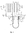
- Figure 1 is a cross-sectional front-elevational view of a cord blood collection apparatus provided in accordance with a first embodiment of the present invention prior illustrated prior to cutting of the umbilical cord.
- Figure 2 is a cross-sectional front-elevational view of the apparatus of Figure 1 illustrated after the umbilical cord is cut.
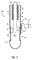
- Figure 3 is a cross-sectional front-elevational view of the cord blood collection apparatus provided in accordance with an embodiment of the present invention, incorporating the apparatus illustrated in Figure 2.
- Figure 4 is a top plan view of an element of the cord blood collection apparatus illustrated in Figure 3.
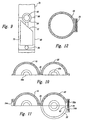
- Figure 5A is a cross-sectional plan view of the apparatus of Figure 1.
- Figure 5B is an enlarged view of a portion of the apparatus illustrated in Figure 5A.
- Figure 6 is a cross-sectional plan view showing an element of the apparatus illustrated in Figure 5A in an alternative position.
- Figure 7 is a cross-sectional front-elevational view of a portion of the apparatus illustrated in Figure 1.
- Figure 8A is a cross-sectional plan view of the apparatus illustrated in Figure 7, without the cord present.
- Figure 8B is a cross-sectional plan view taken along the line 8-8 of Figure 7.
- Figure 9 is a schematic illustration of a cutting blade of the apparatus of Figure 1 shown in a first position.
- Figure 10 is a cross-sectional plan view taken along line 10-10 of Figure 1.
- Figure 11 is a cross-sectional elevational view taken along line 11-11 of Figure 1.
- Figure 12 is a cross-sectional plan view taken along line 12-12 of Figure 1.
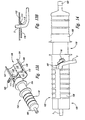
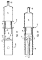
- Figure 13A is a front isometric view of a cord blood collection apparatus provided in accordance with a preferred embodiment of the present invention illustrated in a first, open position.
- Figure 13B is an enlarged, side cross-sectional elevational view of a portion of the apparatus of Figure 13A.
- Figure 14 is a top plan view of the apparatus of Figure 13 illustrated in a closed position.
- Figure 15 is a cross-sectional plan view of the apparatus of Figure 14.
- Figure 16 is a cross-sectional plan view of the apparatus of Figure 15 shown in a second position.
- Figure 17 is a schematic illustration of a preferred embodiment of the present invention.
- the apparatus 100 includes a housing that can be attached to the end of an umbilical cord after the cord has been surgically detached from a baby after delivery.
- the umbilical cord is clamped and the baby is usually placed on the mother's abdomen.
- the cord is clamped with two Kelly clamps or a plastic umbilical cord clamp, and the cord is severed between the two clamps.
- the housing contains a cutting blade that cuts the end of the umbilical cord on the placental side of the clamped cord. The cut, free end of the cord falls into a desired position in the housing, such that blood in the umbilical cord flows via gravity into a blood collection region in an aseptic environment.
- the apparatus of the present invention provides a barrier to prevent the movement of maternal blood, urine, and other contaminating fluids from moving along the outside of the umbilical cord into the collection region.
- the apparatus also shields against splashed and airborne contaminants. It is then possible for the obstetrician, once the housing has been put in place, to massage the uterine fundus prior to the time of disengagement of the placenta from the implantation site, to create a maximum pressure head over the placenta to allow for maximum volume of blood to move into the blood collection region. By massaging the uterus, the placenta is squeezed, thereby increasing the flow of blood out of the umbilical cord and into the blood collection region.
- the apparatus further comprises a placenta bowl that holds the placenta for easy collection of cord blood and which further includes means for compressing the placenta in order to maximize the expulsion of blood through the umbilical cord.
- a placenta bowl that holds the placenta for easy collection of cord blood and which further includes means for compressing the placenta in order to maximize the expulsion of blood through the umbilical cord.
- the placenta bowl and the housing form a system that allows umbilical cord blood to be collected in an aseptic environment in a manner that is more simple and efficient than prior techniques.
- This system can readily be provided in the form of an aseptic kit by providing pre-sterilized individual components in aseptic enclosures, boxed for convenient storage.
- Such a kit would also include a cleaning composition for use in cleaning the umbilical cord in the region where it is placed into the housing of the invention; such cleaning compositions are common in the medical arts.
- FIG. 1 is a cross-sectional front-elevational view of a blood collection apparatus provided in accordance with a first embodiment of the present invention.
- the apparatus includes a housing 100 formed from three parts, which can be separate from each other or flexibly attached to each other, or can themselves be formed from smaller separate parts.
- the three parts include two retaining portions and a sleeve used to collect blood.
- a first retaining portion 10 and a second retaining portion 20 engage each other and together form a unified retainer 30 that engages umbilical cord 5.
- Unified retainer 30 has an external surface 32 and an interior channel 40 having two openings 42 and 44 to an external environment surrounding the unified retainer.
- the channel 40 is adapted to firmly contact an umbilical cord 5 without occluding the flow of blood through the umbilical cord.
- the length of the retaining portions and thus of channel 40 are selected so that the umbilical cord extends through and beyond both ends of channel 40.
- channel 40 is pre-formed, in part, in one of the retaining portions, so that the umbilical cord 5 is pushed through the pre-formed part of the channel 40 prior to being subject to the retaining action of the two retaining portions 10 and 20.
- a regular cord clamp 8 is placed on the umbilical cord 5 prior to cutting the cord at the time of delivery.
- the regular cord clamp is not part of the invention and can be any type of clamp sufficient to stop umbilical cord blood flow and that will allow placement of the cord into the device.
- the end of umbilical cord 5 that is clamped by clamp 8 is placed between the two retaining portions 10 and 20, and the two portions are engaged so that the umbilical cord 5 is held inside channel 40.
- the two openings 42 and 44 of channel 40 are respectively designated the proximal opening 42 and the distal opening 44 to show their orientation relative to the placenta coupled to the cord.
- a sufficient length of cord 5 extends from distal opening 44 so that the remaining operations described below can be carried out.
- the third portion of the housing 100 namely, blood collection sleeve 50, engages with a lower region 34 of unified retainer 30 that surrounds distal opening 44 of channel 40.
- the adjacent surfaces form a junction 60 between sleeve 50 and unified retainer 30.
- a window 62 is present in the junction, the window being formed from a slot or slots present in either or both of the unified retainer 30 and sleeve 50.
- Window 62 is sized to permit passage of umbilical cord 5 through the window, as shown in Figure 1.
- blood collection sleeve 50 comprises upper portion 52, which engages lower portion 34 of the unified retainer 30, and lower portion 51.
- the upper portion 52 contains the blade assembly, and the lower portion 51 serves to collect (or funnel, if attached to an external bag) the cord blood.
- Sleeve upper portion 52 and sleeve lower portion 51 may be different regions of a single integral blood collection sleeve 50 or may be two separate parts which are joined together to form collection sleeve 50. By having the sleeve formed in two parts, visibility and ease of assembly of the sleeve to the unified retainer are improved.
- a blade is located in one of the parts used to form housing 100.
- blade 70 having cutting edge 72, is located in sleeve 50 adjacent to window 62.
- Blade 70 is moveable and cuts umbilical cord 5 when moved in an upward direction as shown in Figure 1. When the blade is in an upward position, blade 70 is positioned across window 62, thus isolating the interior of sleeve 50 from the external environment.
- movement of the blade cuts the umbilical cord for a second time, the first time being during delivery when the umbilical cord is severed to separate the placenta from the newborn so that original clamp 8 and a stump portion 5' of the terminal region of umbilical cord 5 are removed from the end of the umbilical cord.
- the end of the umbilical cord then falls freely and hangs in an interior region 55 of sleeve 50, such that blood flows into and collects in sleeve 50.
- the housing 100 is similar to the housing shown in Figure 2, but the sleeve 50 is adapted so that blood is collected in an external blood collection bag 80 attached to the sleeve via tubing 82, rather than being retained in the sleeve itself.
- Collection bag 80 is a conventional blood-collection bag, such as those distributed by Baxter, Fenwal Division, and is both flexible and aseptic . Flexibility of the terminal collection point of the blood collecting system is desired to prevent build up of internal back pressure when blood flows into the system. Therefore, if a large quantity of blood is collected solely in sleeve 50, sleeve 50 is desirably resilient and expandable. If sleeve 50 is formed from two separate parts, sleeve upper portion 52 and sleeve lower portion 51, then at least sleeve lower portion 51 is resilient and expandable. In a preferred embodiment, the sleeve lower portion 51 is constructed of bloodbag material coated with anticoagulant. If an expandable blood collection bag 80 is attached to the end of sleeve 50, as shown in Figure 3, then sleeve 50 can be either resilient or rigid.
- the housing 100 is attached to a proximal end of umbilical cord 5 and is suspended by the umbilical cord from placenta 2.
- the placenta is placed in a placenta bowl 90 that has a slot 92 which allows the umbilical cord 5 to pass through but which is sufficiently small to retain placenta 2.
- the slot extends from an edge of the container 90 to a gravitational low point of the container when the container is in its normal operating position. This allows blood in the placenta to flow under the influence of gravity into the umbilical cord which extends through slot 92 on the bottom of bowl 90.
- the slot 92 can be closed using slot closure arm 98 as shown in Figure 4, while still allowing the cord to extend through the center of the container.
- the system of the invention provides easy collection of placental blood under aseptic conditions, and it is possible to collect blood from the placenta and umbilical cord directly into a conventional blood-collection bag, which can then be sealed in the normal fashion at the point of entry of blood into the bag. The remaining portions of the system can then be discarded, thereby reducing the chance of biological contamination.
- placenta bowl 90 has a cover 94 and contains an inflatable bladder 96. Inflation of bladder 96 places pressure on the placenta to both increase the rate of blood flow and to insure that the placenta drains substantially completely. It will be understood by one of ordinary skill in the art that other mechanical means for placing external pressure on the placenta, including, but not limited to, hydraulic systems, manually operated systems such as levers and screws, weights, and the like, can be used in place of the inflatable bladder 96.
- the inflatable bladder is used in a preferred embodiment, however, because it is relatively inexpensive and easy to manufacture.
- FIGS 5A and 5B show one embodiment of the two retaining portions 10 and 20 and one manner in which they can be joined together.
- a latch 14 is present on portion 10 with a corresponding catch 24 present on portion 20.
- Latch 14 and catch 24 engage each other when the first and second retaining portions 10 and 20 are placed together to form unified retainer 30.
- the latches are irreversible under normal operating conditions. This can be accomplished by having the latching operation occur in an interior space so that the latch is not accessible after closure for disengagement.
- FIGs 5A and 6 together show how a single apparatus can accommodate umbilical cords of different sizes.
- a semi-circular bushing 61 of resilient material, for example rubber, is present in each of the two retaining portions 10 and 20 so that when the retaining portions are brought together, the bushings form a ring-like structure 63 with an opening 65 in its center which defines channel 40 through which the umbilical cord extends.
- the resiliency of the bushing material is selected so that the bushing will not unduly compress the umbilical cord but will itself be compressed by the umbilical cord.
- the channel 40 expands as shown in Figure 6 when an umbilical cord is placed in the channel.
- the resiliency is sufficient, however, so that close contact is maintained between the resilient material and the exterior surface of the umbilical cord, thus helping to prevent contaminants from passing down the exterior surface of the cord into the collected blood.
- Figures 7 and 8 illustrate an alternative embodiment of the invention in which the two retaining portions 10 and 20 are formed from three materials, namely, a rigid external shell 16, a resilient channel wall 18, and an absorbent fill material 17 positioned between the shell 16 and the channel wall 18.
- both the resilient fill material 17 and the resilient channel wall 18 are pressed outward by the cord in order to accommodate the cord without interrupting blood flow through the cord.
- by-pass channels 15 open in resilient wall 18, thereby allowing excess blood on the exterior of cord 5 to drain through channels 15 and be absorbed by resilient fill material 17.
- the resilient channel wall 18 has projections 19 that mechanically engage umbilical cord 5 and prevent it from being accidentally withdrawn from the housing 100.
- retention of the cord is further achieved by two short small-gauge needles in the housing that puncture the cord upon closure of the assembly.
- Figures 9 and 11 show details of a blade assembly used to cut off the distal end of cord 5.
- a window is formed at junction 60 between unified retainer 30 and sleeve 50.
- one-half of the window 62 is formed in the retainer 30 and the other half of the window is formed in sleeve 50.
- the window 62 can have a resilient seal 64 lining its interior surface, of the same type shown in Figures 5A and 6.
- Blade 70 has a cutting edge 72 and is located in opposed grooves 54 and 55 formed in the walls of both sleeve 50 and unified retainer 30. The lower portion of grooves 54 and 55 in sleeve 50 as aligned with corresponding grooves in the unified retainer.
- Sliding the blade in an upward direction causes cutting edge 72 to pass across window 62, thereby cutting the umbilical cord extending through the window.
- the blade can be moved by a handle 76 attached to blade 70 than extends beyond the grooves 54 and 55.
- a latching mechanism for the handle 76 is provided in an interior region of the blade housing such that once the blade 70 is moved upward, it cannot be moved back to its original position.
- the cutting edge can be recessed in a wall, for example, of the sleeve, and not moved out of its recess until the umbilical cord is in position to be cut.
- a number of alternative embodiments can be used to cut the umbilical cord.
- Figures 10-12 show three cross-sectional plan views taken along lines 10-10, 11-11, and 12-12, respectively, of Figure 1.
- the two retaining portions 10 and 20 of unified retainer 30 are held together by hinge 36 which acts to register the location of the two parts to allow the two parts to be easily assembled.
- hinge 36 acts to register the location of the two parts to allow the two parts to be easily assembled.
- other forms of registration for example, corresponding pins and holes, can be provided in the two parts of the retainer.
- the channel 40 will be formed from the two semi-circular grooves 40a and 40b present in the retaining portions 10 and 20, respectively.
- Figure 12 is a cross-sectional view taken at a lower position on sleeve 50, showing blade 70 in its normal resting position in the wall of sleeve 50.
- the blood collecting apparatus 102 is comprised of a housing 104 having a first portion 106 and a second portion 108 that are slideably movable from a first extended position 110, as illustrated in Figures 14 and 15, to a second collapsed position 112, as illustrated in Figure 16.
- an upper region 120 of the housing 104 is comprised of a first piece 122 and a second piece 124 that engage each other to surround an umbilical cord 5 placed in the housing.
- the first and second pieces 122 and 124 are coupled via a continuous hinge comprised of a pliable, thin section of material extending longitudinally along the intersection between the two pieces. There is therefore no seam or gap to seal, thereby contributing to the aseptic characteristics of the device.
- an inflatable bladder 128 is provided in the upper region of the housing, the bladder being inflatable by the introduction of a volume of gas into the bladder.
- This may be achieved in a variety of ways, for example, by incorporating a pump into the side of the housing, or using a manual squeeze bulb attached to a stem 105 which is in fluid communication with the bladder.
- an umbilical cord 5 is positioned along the length of the upper region of the housing between the first and second pieces 122 and 124, the end of the cord extending through opening 107 to a region external to the housing, as illustrated in Figure 14.
- the first and second pieces 122 and 124 are closed around the cord, engaging each other to form an integral housing, as illustrated in Figure 14.
- the bladder 128 is inflated to a selected pressure and then allowed to deflate to the extent that an inner surface 130 of the bladder is in contact with an outer surface of the umbilical cord, but the pressure from the bladder does not occlude the flow of blood through the cord. Because the bladder is flexible, it conforms to the diameter and irregular surface of the cord, creating a biological barrier to prevent maternal blood and other contaminants from flowing down the length of the cord into the collected blood. To further enhance the biological barrier and ensure that the bladder stays in contact with the cord as the pressure in the cord reduces, an adhesive is provided on the inner surface 130 of the bladder. In a preferred embodiment, a water-based adhesive is used.
- the section of cord enclosed by the bladder in the upper region of the housing is first wiped with alcohol and then dried, prior to being inserted into the housing.
- the apparatus 102 is further provided with a plurality of projections 132 provided in an inner region 114 of the housing adjacent the bladder, the projections 132 grasping the cord and holding it in a desired location.
- the projections 132 are flexible enough to conform to the outer diameter of the cord without constricting the flow of blood through the cord. However, the projections 132 are also sufficiently rigid to keep the cord from sliding.
- the projections 132 are further configured to accommodate and grasp cords of various diameters, without constricting the flow of blood. As illustrated in Figures 15 and 16, each of the projections 132 has a slightly tapered thickness.
- Support 113 is made of an elastomeric material, such as C-Flex (Trademark), Kraton (Trademark), or other synthetic rubber. As illustrated in Figure 13A, the blade 116 cuts through the cord 5, and through a bottom section of the support 113. In this manner, the blade cuts cleanly and completely through the cord.
- a locking mechanism 126 and corresponding locking holes 127 are provided in a side region of the housing, such that when the first and second portions of the housing are moved to the second collapsed position 112, the locking mechanism 126 engages holes 127, thereby preventing the device from being inadvertently opened.
- the tabs 111 Prior to being attached to a cord, the tabs 111 are positioned in aperture 113. When the first and second pieces 122 and 124 are closed, the tabs 111 are depressed, thereby allowing the second portion 108 of the housing to slide towards the first portion 106. The first and second portions 106 and 108 cannot be slid together, which would expose the blade, until the first and second pieces 122 and 124 are engaged.
- the blood collection region 118 of the housing's first portion 106 has a proximal end portion 142, and micro-porous air vents 140 are provided in the proximal end portion.
- the air vents 140 communicate with the blood collection region's interior area to allow air to flow into or out of the interior area during use of the blood collecting apparatus 102. This air flow facilitates the blood flow into and out of the blood collection apparatus during a collection and draining process.
- the blood flow from the umbilical cord filling the blood collection region 118 is greater than the ability of the blood collecting apparatus 102 to drain into, as an example, a blood collection bag, an increased pressure can occur within the blood collection region that may reduce the blood flow rate into the blood collection region, thereby slowing the blood collection process. If the increased pressure in the blood collection region 118 is too high relative to the cord blood pressure, the blood flow from the umbilical cord will be slowed. Accordingly, the air vents 140 minimize the pressure differential within the blood collection region 118 by allowing air to exit the blood collection region as the blood is collected in the blood collection region.
- the air vents 140 also minimize negative pressures in the blood collecting region 118 that may occur as the blood flows out of the blood collecting region and into a blood bag or other secondary blood collection container. Accordingly, the air vents 140 allow the blood to be quickly drained into the blood collection bag to minimize the overall time required to collect and process the umbilical cord and placenta blood.
- the micro-porous air vents 140 of the illustrated alternate embodiment are made from a porous plastic material that allows air to flow out of and into the blood collection region 118 as needed as blood enters and exists the blood collection region, respectively.
- the preferred porous plastic is also hydrophobic so as to repel liquids, and particularly blood, while allowing air and other gases to pass therethrough.
- the porous plastic is leak proof to prevent loss of any blood through the air vents 140.
- the pore size within the porous plastic is sufficiently large to allow a free flow of air through the air vents 140 while being small enough to substantially prevent airborne organisms from passing through the air vent which could contaminate the collected blood.
- the blood collecting apparatus's housing 104 has generally triangularly-shaped flanges 144 attached to the first and second portions 106 and 108.
- the flanges 144 are spaced apart from each other, and when the first and second portions are slid together in the collapsed position, the flange portions are adjacent to each other.
- the flanges 144 are shaped such that when the blood collection apparatus 102 is set on a table or other support surface, the apparatus will be positioned in one of three orientations as defined by the triangular-shaped flanges.
- the flanges 144 each have three lobe portions 146 projecting away from the respective first or second portion, 106 or 108
- the air vents 140 on the blood collecting region's proximal portion are each positioned generally adjacent to a respective lobe portion 146.
- At least one air vent 140 is always positioned so it faces upwardly when the blood collection apparatus is set on a generally horizontal support surface. Accordingly, at least one of the air vents 140 is kept clear and not coated by the blood in the blood collection region 118, thereby ensuring proper air flow through the air vent to minimize any pressure differentials within the blood collection region.
- the exterior surface of the housing is ribbed, allowing the user to grasp it firmly.
- the opening 107 is closed, thereby maintaining the aseptic condition, and allowing the volume of blood to be collected in an aseptic environment.
- a large quantity of blood may therefore be collected from an umbilical cord in an aseptic manner using an apparatus provided in accordance with a preferred embodiment of the present invention, by placing an umbilical cord 5 into a housing having an inner region adapted to receive the cord, step 135.
- the inner region of the housing is isolated from the external environment, step 136, thereby allowing the collection to proceed in an aseptic environment.
Landscapes
- Health & Medical Sciences (AREA)
- Life Sciences & Earth Sciences (AREA)
- Engineering & Computer Science (AREA)
- Heart & Thoracic Surgery (AREA)
- Public Health (AREA)
- Veterinary Medicine (AREA)
- Biomedical Technology (AREA)
- Hematology (AREA)
- Animal Behavior & Ethology (AREA)
- General Health & Medical Sciences (AREA)
- Molecular Biology (AREA)
- Surgery (AREA)
- Medical Informatics (AREA)
- Pathology (AREA)
- Physics & Mathematics (AREA)
- Biophysics (AREA)
- Dermatology (AREA)
- Manufacturing & Machinery (AREA)
- Pain & Pain Management (AREA)
- Vascular Medicine (AREA)
- Anesthesiology (AREA)
- Gynecology & Obstetrics (AREA)
- Pregnancy & Childbirth (AREA)
- Reproductive Health (AREA)
- External Artificial Organs (AREA)
- Medicines Containing Material From Animals Or Micro-Organisms (AREA)
- Measurement Of The Respiration, Hearing Ability, Form, And Blood Characteristics Of Living Organisms (AREA)
Claims (44)
- Appareil pour collecter du sang à partir d'un cordon ombilical (5), comportant :caractérisé en ce que la région intérieure du boítier (100) n'engage qu'une partie d'un cordon ombilical (5) afin qu'une extrémité d'un cordon ombilical coupé (5) pende librement dans la région intérieure et que du sang s'écoule par gravité du cordon ombilical (5) dans la région (50) de collecte du sang.un boítier (100) ayant un canal (40) dans une région intérieure, le boítier ayant une ouverture (62) en communication avec le canal (40) et en communication avec une région extérieure au boítier, un cordon ombilical (5) pouvant être passé dans le canal (40) et s'étendant à travers l'ouverture (62) ;une lame (70) reliée de façon mobile au boítier (100), la lame (70) étant positionnée de façon à se déplacer d'une première position, à travers l'ouverture (62), jusqu'à une seconde position, coupant ainsi un cordon ombilical (5) s'étendant à travers l'ouverture ; etune région (50) de collecte de sang en communication de fluide avec la région intérieure du boítier, le boítier (100) étant sensiblement fermé à l'environnement extérieur de façon que le sang provenant d'un cordon ombilical (5) soit collecté dans un environnement sensiblement aseptique ;
- Appareil selon la revendication 1, dans lequel le boítier (100) comporte en outre une première pièce (10) et une seconde pièce (20), les première et seconde pièces (10, 20) réalisant un engagement entre elles après qu'un cordon ombilical (5) a été placé entre les première et seconde pièces (10, 20), entourant ainsi le cordon ombilical (5).
- Appareil selon la revendication 2, dans lequel les première et seconde pièces (10, 20) sont formées chacune d'une coque extérieure rigide (16), d'une paroi élastique (18) de canal, et d'une matière élastique et poreuse (17) de remplissage située entre la coque (16) et la paroi (18) du canal.
- Appareil selon l'une quelconque des revendications précédentes, comportant en outre des gorges opposées (54, 55) prévues dans une surface extérieure du boítier (100) à proximité immédiate de l'ouverture, la lame (70) se déplaçant de la première position à la seconde position en coulissant dans les gorges (54, 55).
- Appareil selon l'une quelconque des revendications précédentes, comportant en outre une vessie gonflable (96) positionnée dans la région intérieure du boítier (100) concentriquement avec le canal (40), un volume de gaz étant prévu pour gonfler la vessie (96) afin qu'une surface intérieure de la vessie (96) soit adjacente à une surface extérieure d'un cordon ombilical (5).
- Appareil selon l'une quelconque des revendications précédentes, comportant en outre plusieurs saillies élastiques (19) situées sur une paroi intérieure du canal (40), les saillies élastiques (19) saisissant et maintenant un cordon ombilical (5) dans un emplacement souhaité.
- Appareil selon l'une quelconque des revendications précédentes, dans lequel la région (50) de collecte de sang est flexible.
- Appareil selon l'une quelconque des revendications précédentes, comportant en outre un récipient (90) relié au boítier (100), le récipient (90) recevant un placenta (2) et ayant une ouverture (92) à travers laquelle un cordon ombilical (5) peut passer.
- Appareil selon la revendication 8, dans lequel le récipient (90) comporte un couvercle (94) qui isole une région intérieure du récipient (90) de l'environnement extérieur au récipient (90).
- Appareil pour la collecte de sang à partir d'un cordon ombilical, comportant :caractérisé en ce que les première et seconde parties (106, 108) sont mobiles de façon coulissante d'une première position déployée à une seconde position refermée ; la lame (116) coupant un cordon ombilical (5) maintenu par le boítier (104) lorsque les première et seconde parties (106, 108) sont déplacées en coulissant vers la seconde position refermée, l'extrémité coupée du cordon ombilical (5) tombant librement dans la région intérieure (114) du boítier (104) afin que du sang s'écoule par gravité du cordon ombilical (5) dans la région (118) de collecte de sang.un boítier (104) ayant une première partie (106) et une seconde partie (108) ;une lame (116) reliée à la première partie (106) du boítier (104) ; etune région (118) de collecte de sang en communication de fluide avec la région (114) intérieure du boítier (104) ;
- Appareil selon la revendication 10, dans lequel une région supérieure (120) du boítier comporte en outre une première pièce (122) et une seconde pièce (124), les première et seconde pièces (122, 124) réalisant un engagement l'une avec l'autre après qu'un cordon ombilical (5) a été placé entre les première et seconde pièces (122, 124), entourant ainsi le cordon ombilical (5).
- Appareil selon la revendication 2 ou 11, dans lequel les première et seconde pièces (122, 124) sont reliées par une charnière.
- Appareil selon la revendication 2, 11 ou 12, dans lequel un mécanisme de verrouillage est prévu sur le boítier afin que les première et seconde pièces (122, 124) soient engagées de façon verrouillée.
- Appareil selon la revendication 2, 11 ou 12, dans lequel les première et seconde pièces (122, 124) sont engagées en accouplement.
- Appareil selon la revendication 10 ou l'une quelconque des revendications qui en dépendent, comportant en outre une vessie gonflable (128) positionnée dans la région intérieure (114) du boítier (104) concentriquement à un canal s'étendant longitudinalement à travers une région supérieure (120) du boítier (104), un volume de gaz étant prévu pour gonfler la vessie (128) afin qu'une surface intérieure (130) de la vessie (128) soit adjacente à une surface extérieure d'un cordon ombilical (5) s'étendant dans le canal.
- Appareil selon la revendication 15, comportant en outre plusieurs saillies élastiques (132) situées sur une paroi intérieure du canal à proximité immédiate de la vessie gonflable (128), les saillies élastiques (132) saisissant et maintenant un cordon ombilical (5) dans un emplacement souhaité.
- Appareil selon la revendication 10, comportant en outre plusieurs saillies élastiques (132) situées sur une paroi intérieure d'un canal s'étendant à travers une région supérieure (120) du boítier (104), les saillies élastiques (132) saisissant et maintenant un cordon ombilical (5) dans une position souhaitée.
- Appareil selon l'une quelconque des revendications 10 à 17, comportant en outre un revêtement anti-coagulant situé sur une surface intérieure de la région (118) de collecte du sang.
- Appareil selon l'une quelconque des revendications 10 à 18, comportant en outre un support (113) relié au boítier (104) afin que, lorsque le cordon ombilical (5) est maintenu par le boítier (104), le cordon (5) soit positionné entre la lame (116) et le support (113).
- Appareil selon l'une quelconque des revendications 10 à 19, comportant en outre un évent (140) de mise à l'air en communication avec la région intérieure (114) et la région (118) de collecte du sang pour ventiler la région (118) de collecte du sang et minimiser des différences de pression à l'intérieur de la région (118) de collecte du sang pendant que du sang afflue dans la région (118) de collecte du sang.
- Appareil selon l'une quelconque des revendications précédentes, comportant en outre un clapet de retenue (134) positionné dans le boítier (104) en communication de fluide avac la région intérieure (114) et la région (118) de collecte du sang.
- Appareil selon la revendication 5 ou 15, dans lequel un adhésif est prévu sur la surface intérieure de la vessie.
- Appareil selon l'une quelconque des revendications précédentes, comportant en outre une poche élastique (80) reliée à la région (50, 118) de collecte du sang.
- Appareil selon la revendication 23, comportant en outre un revêtement anti-coagulant prévu sur une surface intérieure de la poche (80) et de la région (50, 118) de collecte du sang.
- Appareil selon l'une quelconque des revendications 10 à 24, comportant en outre un récipient (90), le récipient (90) recevant un placenta (2) et ayant une ouverture (92) à travers laquelle un cordon ombilical (5) peut passer.
- Appareil selon la revendication 8 ou 25, comportant en outre des moyens (96) destinés à comprimer un placenta dans le récipient (90).
- Appareil selon la revendication 11, comportant en outre un mécanisme de verrouillage (126) qui empêche les première et seconde parties (106, 108) de se déplacer vers la seconde position repliée jusqu'à ce que les première et seconde pièces (122, 124) soient engagées, empêchant ainsi l'utilisateur d'être exposé à la lame (116).
- Appareil selon la revendication 1 ou 10, comportant en outre un évent (10) de mise à l'air dans la région (50, 118) de collecte du sang, l'évent (140) étant dimensionné pour permettre à de l'air de s'écouler en entrée et en sortie de la région (50, 118) de collecte du sang pendant que du sang afflue dans la région (50, 118) de collecte du sang.
- Appareil selon la revendication 28, dans lequel l'évent (140) de mise à l'air comprend une matière choisie ayant des pores dimensionnés pour permettre à de l'air de s'écouler à travers elle tout en empêchant de sang de passer à travers elle.
- Appareil selon la revendication 29, dans lequel la matière choisie est hydrophobe afin de repousser un fluide tout en permettant à de l'air de s'écouler à travers elle.
- Appareil selon la revendication 28, comportant en outre un élément (144) de positionnement relié à l'un du boítier (100, 104) et de la région (50, 118) de collecte du sang, l'élément de positionnement (144) étant configuré de façon à supporter le boítier (110, 104) et la région (50, 118) de collecte du sang dans l'une de plusieurs positions choisies avec l'évent (140) de mise à l'air non obturé par du sang se trouvant dans la région (50, 118) de collecte du sang.
- Appareil selon la revendication 31, dans lequel l'élément de positionnement (144) comporte une collerette ayant une forme globalement triangulaire.
- Appareil selon la revendication 31, dans lequel l'élément de positionnement (144) comporte plusieurs parties à lobes (146) faisant saillie à l'écart de l'un du boítier (100, 104) et de la région (50, 118) de collecte du sang et l'évent (140) de mise à l'air est sensiblement adjacent à l'une des parties à lobes (146).
- Appareil selon la revendication 28, comportant en outre une collerette (144) de positionnement reliée à l'un du boítier (110, 104) et de la région (50, 118) de collecte du sang, la collerette (144) de positionnement étant configurée de façon à supporter le boítier (100, 104) et la région (50, 118) de collecte du sang dans l'une de plusieurs positions choisies, avec l'évent (140) de mise à l'air non obturé par du sang se trouvant dans la région (50, 118) de collecte.
- Appareil selon la revendication 34, dans lequel la collerette (144) de positionnement a une forme globalement triangulaire avec trois parties à lobes (146), et l'évent (140) de mise à l'air est sensiblement adjacent à l'une des parties à lobes (146).
- Appareil selon la revendication 34, dans lequel la collerette (144) de positionnement comporte plusieurs parties à lobes (146) faisant saillie à l'écart de la région (50, 118) de collecte du sang, et l'évent (140) de mise à l'air est sensiblement adjacent à l'une des parties à lobes (146).
- Appareil selon la revendication 34, dans lequel l'évent (140) de mise à l'air est un premier évent (140) de mise à l'air et comporte en outre des deuxième et troisième évents (140) de mise à l'air dans la région (50, 118) de collecte du sang, et la collerette (144) de positionnement présente une forme globalement trilobulaire avec trois parties à lobes (146) espacées autour de la région (50, 118) de collecte du sang, chacun des premier, deuxième et troisième évents (140) de mise à l'air est sensiblement adjacent à l'une, respective, des trois parties à lobes (146).
- Appareil selon la revendication 28 ou l'une quelconque des revendications 34 à 39, dans lequel la région (50, 118) de collecte du sang contient une sortie positionnée pour permettre à du sang se trouvant dans la région (50, 118) de collecte du sang de s'écouler à l'extérieur de la région (50, 118) de collecte du sang, et l'évent (140) de mise à l'air est configuré et dimensionné pour permettre à de l'air de s'écouler à travers lui jusque dans la région (50, 118) de collecte du sang en même temps que du sang s'écoule en sortie de la région (50, 118) de collecte du sang.
- Procédé pour collecter un volume de sang à partir d'un cordon ombilical (5) dans un environnement aseptique, comprenant :la mise en place d'un cordon ombilical (5) dans un boítier ayant une région intérieure conçue pour recevoir le cordon ;l'isolation de la région intérieure du boítier (100, 104) de l'environnement extérieur ;la coupe du cordon ombilical (5) afin que l'extrémité coupée du cordon soit positionnée dans la région intérieure (114) du boítier (110, 104) et que du sang s'écoule par gravité du cordon dans la région intérieure (114).
- Procédé selon la revendication 40, comprenant en outre :la mise en place d'un placenta (2) relié au cordon ombilical (5) dans un récipient (90) ayant une ouverture (92) à travers laquelle le cordon ombilical (5) s'étend ; et la compression du placenta (2).
- Procédé selon la revendication 39 ou 40, comprenant en outre :le passage de l'air à travers un évent (140) de mise à l'air qui communique avec la région intérieure (114) pour minimiser une différence de pression entre la région intérieure (114) et l'environnement extérieur.
- Procédé selon la revendication 41, comprenant en outre l'étape de positionnement du boítier (100, 104) sur une structure de support choisie (144) de façon que l'évent (140) de mise à l'air ne soit pas obturé par le sang.
- Procédé selon l'une quelconque des revendications 39 à 42, dans lequel le boítier (104) comporte une première partie (106) et une seconde partie (108), les première et seconde parties (106, 108) pouvant être déplacées de façon coulissante d'une première position déployée à une seconde position repliée, la première partie (106) comportant en outre une première pièce (122) et une seconde pièce (124) qui s'engagent l'une avec l'autre pour entourer le cordon ombilical (5), le procédé comprenant en outre :la fermeture des première et seconde pièces (122, 124) du boítier (104) pour entourer le cordon ombilical (5) ;le gonflage d'une vessie (122) positionnée dans la région intérieure (144) du boítier (104) concentriquement à un canal s'étendant longitudinalement à travers une région supérieure (120) du boítier (104), de façon que la vessie (128) vienne en contact avec une surface extérieure du cordon ombilical (5) et en épouse la forme ; et dans lequel l'étape de coupe du cordon ombilical comprend :le coulissement des première et seconde parties (106, 108) du boítier (104) de la première position déployée à la seconde position repliée, coupant ainsi le cordon ombilical (5) au moyen d'une lame (116) reliée au boítier (104), l'extrémité coupée du cordon ombilical (5) tombant librement dans la région intérieure (114) du boítier (104), du sang s'écoulant par gravité du cordon ombilical (5) dans une région (118) de collecte du sang.
- Procédé selon l'une quelconque des revendications 39 à 42, dans lequel l'étape de mise en place d'un cordon ombilical (5) dans un boítier comprend :dans lequel l'étape de coupe du cordon ombilical (5) comprend :la mise en place du cordon ombilical (5) dans un canal (40) prévu dans la région intérieure du boítier (100), et le passage d'une extrémité du cordon ombilical (5) à travers une ouverture (62) qui est en communication avec le canal (40) et qui est en communication avec une région extérieure au boítier, afin que le cordon ombilical (5) passe dans le canal (40) et s'étende à travers l'ouverture (62) ; et dans lequel l'étape d'isolation de la région intérieure comprend :la fermeture de première et seconde parties (10, 20) du boítier (100) afin d'entourer le cordon ombilical (5) ; etle coulissement d'une lame (70) reliée de façon mobile au boítier (100) d'une première position, à travers l'ouverture (62), jusqu'à une seconde position, coupant ainsi le cordon ombilical (5), l'extrémité coupée du cordon ombilical (5) tombant librement dans la région intérieure du boítier (100) et du sang s'écoulant par gravité du cordon ombilical (5) dans la région (50) de collecte du sang.
Applications Claiming Priority (5)
| Application Number | Priority Date | Filing Date | Title |
|---|---|---|---|
| US742438 | 1991-08-08 | ||
| US1740296P | 1996-05-14 | 1996-05-14 | |
| US17402P | 1996-05-14 | ||
| US08/742,438 US5919176A (en) | 1996-05-14 | 1996-10-30 | Apparatus and method for collecting blood from an umbilical cord |
| PCT/US1997/008226 WO1997042872A1 (fr) | 1996-05-14 | 1997-05-14 | Appareil et procede permettant de recuperer le sang a partir d'un cordon ombilical |
Publications (2)
| Publication Number | Publication Date |
|---|---|
| EP0910279A1 EP0910279A1 (fr) | 1999-04-28 |
| EP0910279B1 true EP0910279B1 (fr) | 2003-04-16 |
Family
ID=26689825
Family Applications (1)
| Application Number | Title | Priority Date | Filing Date |
|---|---|---|---|
| EP97927641A Expired - Lifetime EP0910279B1 (fr) | 1996-05-14 | 1997-05-14 | Appareil et procede permettant de recuperer le sang a partir d'un cordon ombilical |
Country Status (12)
| Country | Link |
|---|---|
| US (4) | US5919176A (fr) |
| EP (1) | EP0910279B1 (fr) |
| JP (1) | JP3759171B2 (fr) |
| AT (1) | ATE237280T1 (fr) |
| CA (1) | CA2254071C (fr) |
| DE (1) | DE69720994T2 (fr) |
| DK (1) | DK0910279T3 (fr) |
| ES (1) | ES2198575T3 (fr) |
| HK (1) | HK1019700A1 (fr) |
| IL (1) | IL127041A (fr) |
| PT (1) | PT910279E (fr) |
| WO (1) | WO1997042872A1 (fr) |
Families Citing this family (57)
| Publication number | Priority date | Publication date | Assignee | Title |
|---|---|---|---|---|
| US5919176A (en) | 1996-05-14 | 1999-07-06 | Children's Hospital Medical Center Of Northern California | Apparatus and method for collecting blood from an umbilical cord |
| WO2001076660A2 (fr) * | 2000-04-10 | 2001-10-18 | Johns Hopkins University | Methodes de collecte du sang du cordon ombilical et dispositifs associes |
| US7311905B2 (en) | 2002-02-13 | 2007-12-25 | Anthrogenesis Corporation | Embryonic-like stem cells derived from post-partum mammalian placenta, and uses and methods of treatment using said cells |
| US20080152629A1 (en) * | 2000-12-06 | 2008-06-26 | James Edinger | Placental stem cell populations |
| EP2322601A1 (fr) | 2000-12-06 | 2011-05-18 | Anthrogenesis Corporation | Procédé de collecte de cellules souche placentaires |
| WO2002064036A1 (fr) * | 2001-02-13 | 2002-08-22 | Dao-Pei Lu | Appareil et procede pour recueillir le sang residuel a partir du placenta |
| IL157350A0 (en) * | 2001-02-14 | 2004-02-19 | Anthrogenesis Corp | Post-partum mammalian placenta, its use and placental stem cells therefrom |
| US7118559B2 (en) * | 2002-05-24 | 2006-10-10 | Tyco Healthcare Group Lp | Body fluid collection apparatus |
| US7588562B2 (en) * | 2002-05-24 | 2009-09-15 | Tyco Healthcare Group Lp | Body fluid collection apparatus |
| AU2003298775B2 (en) * | 2002-11-26 | 2008-07-17 | Anthrogenesis Corporation | Cytotherapeutics, cytotherapeutic units and methods for treatments using them |
| EP1601248A4 (fr) * | 2003-02-13 | 2010-01-27 | Anthrogenesis Corp | Utilisation de sang de cordon ombilical pour traiter des individus presentant une maladie, un trouble ou une pathologie |
| DE10310533B4 (de) * | 2003-03-11 | 2005-08-11 | Fraunhofer-Gesellschaft zur Förderung der angewandten Forschung e.V. | Verfahren und Vorrichtung zur Gewinnung von Nabelschnurblut |
| US7332334B2 (en) * | 2003-04-18 | 2008-02-19 | Oklahoma Medical Research Foundation | Hematopoietic stem cells treated by in vitro fucosylation and methods of use |
| GB0321337D0 (en) * | 2003-09-11 | 2003-10-15 | Massone Mobile Advertising Sys | Method and system for distributing advertisements |
| EP1694328A4 (fr) * | 2003-12-02 | 2010-02-17 | Celgene Corp | Procedes et compositions de traitement et de gestion de l'hemoglobinopathie et de l'anemie |
| US7097554B2 (en) * | 2003-12-12 | 2006-08-29 | Hyclone Laboratories, Inc. | Animal fetus blood procurement tables and methods |
| US20060020227A1 (en) * | 2004-07-20 | 2006-01-26 | Moore Thomas E | Collection means and a method for collecting cord blood |
| US7909806B2 (en) * | 2004-09-23 | 2011-03-22 | Anthrogenesis Corporation | Cord blood and placenta collection kit |
| US7147626B2 (en) * | 2004-09-23 | 2006-12-12 | Celgene Corporation | Cord blood and placenta collection kit |
| SG122835A1 (en) * | 2004-12-01 | 2006-06-29 | Univ Singapore | Umbilical cord blood collection apparatus |
| AU2006290286A1 (en) * | 2005-09-15 | 2007-03-22 | Situgen Ltd. | Apparatus and method for collecting cord blood |
| NZ612132A (en) | 2005-10-13 | 2015-01-30 | Anthrogenesis Corp | Immunomodulation using placental stem cells |
| ES2549111T3 (es) | 2005-12-29 | 2015-10-23 | Anthrogenesis Corporation | Poblaciones de células madre placentarias |
| WO2007079184A2 (fr) | 2005-12-29 | 2007-07-12 | Anthrogenesis Corporation | Co-culture de cellules souches placentaires et cellules souches provenant d'une seconde source |
| US8157774B1 (en) * | 2006-03-16 | 2012-04-17 | Deka Products Limited Partnership | Apparatus for stem cell collection and methods thereof |
| US7654968B1 (en) * | 2006-07-28 | 2010-02-02 | Horvat Branimir L | Placental blood extractor |
| JP2010518812A (ja) | 2007-02-12 | 2010-06-03 | アンスロジェネシス コーポレーション | 接着性胎盤幹細胞由来の肝細胞および軟骨細胞、ならびにcd34+、cd45−胎盤幹細胞の濃縮細胞集団 |
| NZ597779A (en) | 2007-02-12 | 2013-07-26 | Anthrogenesis Corp | Treatment of inflammatory diseases using placental stem cells |
| US20100172830A1 (en) * | 2007-03-29 | 2010-07-08 | Cellx Inc. | Extraembryonic Tissue cells and method of use thereof |
| TWM322542U (en) * | 2007-05-23 | 2007-11-21 | Universal Scient Ind Co Ltd | Testing machine |
| US9200253B1 (en) | 2007-08-06 | 2015-12-01 | Anthrogenesis Corporation | Method of producing erythrocytes |
| KR20220122774A (ko) * | 2007-09-26 | 2022-09-02 | 셀룰래리티 인코포레이티드 | 인간 태반 관류액으로부터의 혈관형성 세포 |
| DK2203176T3 (en) | 2007-09-28 | 2015-02-09 | Anthrogenesis Corp | Tumor suppression with human placental perfusate and human natural killer cells of an intermediate product from placenta |
| CN101909694A (zh) * | 2007-11-07 | 2010-12-08 | 人类起源公司 | 脐带血在治疗早产并发症中的用途 |
| CA2719825C (fr) * | 2008-03-27 | 2018-11-06 | Biolife Solutions, Inc. | Materiaux et procedes pour le prelevement hypothermique de sang total |
| EP3172963B1 (fr) | 2008-08-20 | 2019-02-06 | Celularity, Inc. | Composition améliorée de cellules et son procédé de fabrication |
| CN105796602A (zh) | 2008-08-20 | 2016-07-27 | 人类起源公司 | 利用分离的胎盘细胞治疗中风 |
| MX339068B (es) | 2008-08-22 | 2016-05-10 | Anthrogenesis Corp | Metodos y composiciones para el tratamiento de defectos oseos con poblaciones de celulas placentarias. |
| WO2010052706A1 (fr) * | 2008-11-04 | 2010-05-14 | Situ Gen Ltd. | Procédé et moyen de collecte de sang ombilical |
| MX2011005229A (es) | 2008-11-19 | 2011-06-16 | Anthrogenesis Corp | Celulas adherentes derivadas del amnios. |
| AU2009316376B2 (en) * | 2008-11-21 | 2015-08-20 | Celularity Inc. | Treatment of diseases, disorders or conditions of the lung using placental cells |
| MX2012000110A (es) | 2009-07-02 | 2012-04-02 | Anthrogenesis Corp | Metodo para producir eritrocitos sin celulas alimetadoras. |
| US9121007B2 (en) | 2010-01-26 | 2015-09-01 | Anthrogenesis Corporatin | Treatment of bone-related cancers using placental stem cells |
| TW201902496A (zh) | 2010-04-07 | 2019-01-16 | 美商安瑟吉納西斯公司 | 利用胎盤幹細胞之血管新生 |
| JP2013523823A (ja) | 2010-04-08 | 2013-06-17 | アントフロゲネシス コーポレーション | 胎盤幹細胞を用いるサルコイドーシスの治療 |
| CN107760648A (zh) | 2010-07-13 | 2018-03-06 | 人类起源公司 | 产生自然杀伤细胞的方法、由此获得的细胞群体及其用途 |
| EP2658557A1 (fr) | 2010-12-31 | 2013-11-06 | Anthrogenesis Corporation | Amélioration de l'efficacité de cellules souches placentaires sous l'effet de molécules d'arn modulateur |
| EP2714059B1 (fr) | 2011-06-01 | 2018-10-03 | Celularity, Inc. | Traitement de la douleur à l'aide de cellules souches placentaires |
| US9168030B2 (en) | 2011-08-11 | 2015-10-27 | Robert A. Dracker | Envelope and procurement stand for placental transport and stem cell collection |
| US9925221B2 (en) | 2011-09-09 | 2018-03-27 | Celularity, Inc. | Treatment of amyotrophic lateral sclerosis using placental stem cells |
| US9526478B2 (en) * | 2011-12-22 | 2016-12-27 | The Johns Hopkins University | Cord blood perfusion and collection system |
| SG192306A1 (en) * | 2012-01-27 | 2013-08-30 | Sg Meditech Pte Ltd | Placental blood extraction device |
| GB2506889A (en) * | 2012-10-10 | 2014-04-16 | Virgin Health Bank Qstp Llc | Collecting placenta and umbilical cord blood |
| EP3622960A1 (fr) | 2013-02-05 | 2020-03-18 | Celularity, Inc. | Cellules tueuses naturelles placentaires |
| US10028749B2 (en) * | 2015-11-16 | 2018-07-24 | Children's Hospital & Research Center At Oakland | Cord collection clamp |
| DE102017109723A1 (de) * | 2017-05-05 | 2018-11-08 | Eberhard Karls Universität Tübingen Medizinische Fakultät | Medizinische Vorrichtung zur Legung eines Katheters |
| IT202200002873A1 (it) * | 2022-02-16 | 2023-08-16 | Pfm Medical Ag | Dispositivo per assistere nel posizionamento di un catetere ombelicale in neonati prematuri e neonati |
Family Cites Families (18)
| Publication number | Priority date | Publication date | Assignee | Title |
|---|---|---|---|---|
| US4781188A (en) * | 1986-09-22 | 1988-11-01 | Collins Jason H | Umbilical cord clamp apparatus |
| US4856517A (en) * | 1986-09-22 | 1989-08-15 | Collins Jason H | Umbilical cord clamp apparatus |
| US5192553A (en) * | 1987-11-12 | 1993-03-09 | Biocyte Corporation | Isolation and preservation of fetal and neonatal hematopoietic stem and progenitor cells of the blood and methods of therapeutic use |
| US5004681B1 (en) * | 1987-11-12 | 2000-04-11 | Biocyte Corp | Preservation of fetal and neonatal hematopoietic stem and progenitor cells of the blood |
| US5059186A (en) | 1988-03-07 | 1991-10-22 | Vitaphore Corporation | Percutaneous access device |
| IE902301A1 (en) * | 1989-12-22 | 1991-07-03 | Cryo Cell Internat | Identification Process And Related Method For Use In¹Preparing A Biological Sample |
| EP0438626A3 (en) * | 1990-01-26 | 1992-03-11 | Cryo-Cell International Inc. | Apparatus for preparing an elongate fluid-containing member and related apparatus for removing fluid from such member |
| US5114672A (en) * | 1990-08-27 | 1992-05-19 | Cryo-Cell International, Inc. | Method for preserving blood fluid |
| US5053025A (en) * | 1990-09-04 | 1991-10-01 | Cryo-Cell International, Inc. | Method and apparatus for extracting fluid |
| US5059168A (en) * | 1990-10-02 | 1991-10-22 | Stone Joseph J | Neonatal autotransfusion apparatus and method |
| US5190556A (en) * | 1991-03-19 | 1993-03-02 | O.B. Tech, Inc. | Cord cutter sampler |
| US5356373A (en) * | 1991-11-15 | 1994-10-18 | Miles Inc. | Method and apparatus for autologous transfusions in premature infants |
| US5342328A (en) * | 1993-03-22 | 1994-08-30 | Grossman Michael D | Medical body fluid sampler device and method |
| US5372581A (en) * | 1993-07-21 | 1994-12-13 | Minneapolis Children's Services Corporation | Method and apparatus for placental blood collection |
| US5372481A (en) * | 1993-11-29 | 1994-12-13 | Solar Turbine Incorporated | Ceramic blade attachment system |
| US5575796A (en) * | 1995-05-17 | 1996-11-19 | Utah Medical Products, Inc. | Umbilical cord cutter and sampler |
| US5676672A (en) * | 1995-11-08 | 1997-10-14 | Watson; Thomas J. | Umbilical cord clamps with shielded cutter |
| US5919176A (en) | 1996-05-14 | 1999-07-06 | Children's Hospital Medical Center Of Northern California | Apparatus and method for collecting blood from an umbilical cord |
-
1996
- 1996-10-30 US US08/742,438 patent/US5919176A/en not_active Expired - Lifetime
-
1997
- 1997-05-14 AT AT97927641T patent/ATE237280T1/de active
- 1997-05-14 PT PT97927641T patent/PT910279E/pt unknown
- 1997-05-14 US US08/856,252 patent/US5993429A/en not_active Expired - Lifetime
- 1997-05-14 ES ES97927641T patent/ES2198575T3/es not_active Expired - Lifetime
- 1997-05-14 WO PCT/US1997/008226 patent/WO1997042872A1/fr active IP Right Grant
- 1997-05-14 DK DK97927641T patent/DK0910279T3/da active
- 1997-05-14 IL IL12704197A patent/IL127041A/xx not_active IP Right Cessation
- 1997-05-14 EP EP97927641A patent/EP0910279B1/fr not_active Expired - Lifetime
- 1997-05-14 DE DE69720994T patent/DE69720994T2/de not_active Expired - Lifetime
- 1997-05-14 CA CA002254071A patent/CA2254071C/fr not_active Expired - Lifetime
- 1997-05-14 JP JP54111797A patent/JP3759171B2/ja not_active Expired - Fee Related
-
1999
- 1999-05-12 US US09/310,895 patent/US6190368B1/en not_active Expired - Lifetime
- 1999-10-28 HK HK99104863A patent/HK1019700A1/xx not_active IP Right Cessation
-
2000
- 2000-12-18 US US09/740,616 patent/US6440110B2/en not_active Expired - Lifetime
Also Published As
| Publication number | Publication date |
|---|---|
| HK1019700A1 (en) | 2000-02-25 |
| CA2254071A1 (fr) | 1997-11-20 |
| EP0910279A1 (fr) | 1999-04-28 |
| US20020002355A1 (en) | 2002-01-03 |
| DE69720994D1 (de) | 2003-05-22 |
| US6190368B1 (en) | 2001-02-20 |
| IL127041A (en) | 2003-12-10 |
| JP3759171B2 (ja) | 2006-03-22 |
| US6440110B2 (en) | 2002-08-27 |
| JP2000510734A (ja) | 2000-08-22 |
| CA2254071C (fr) | 2007-07-24 |
| WO1997042872A1 (fr) | 1997-11-20 |
| IL127041A0 (en) | 1999-09-22 |
| DE69720994T2 (de) | 2004-02-05 |
| ATE237280T1 (de) | 2003-05-15 |
| AU736781B2 (en) | 2001-08-02 |
| US5919176A (en) | 1999-07-06 |
| PT910279E (pt) | 2003-09-30 |
| US5993429A (en) | 1999-11-30 |
| AU3206197A (en) | 1997-12-05 |
| ES2198575T3 (es) | 2004-02-01 |
| DK0910279T3 (da) | 2003-08-11 |
Similar Documents
| Publication | Publication Date | Title |
|---|---|---|
| EP0910279B1 (fr) | Appareil et procede permettant de recuperer le sang a partir d'un cordon ombilical | |
| US9375168B2 (en) | Apparatus and method for collecting cord blood | |
| AU780718B2 (en) | Blood processing set including an integrated blood sampling system | |
| US8079997B2 (en) | Apparatus for collecting blood samples | |
| EP0935475B1 (fr) | Appareil d'extraction de fluides | |
| JP2002534203A (ja) | 液体試料を得るための装置 | |
| US6302854B1 (en) | Method for collecting fluids | |
| EP0935481A1 (fr) | Ensemble de connecteur pour collecter des fluides | |
| Tan et al. | Devices for umbilical cord blood collection | |
| AU2005202959B2 (en) | Blood processing set including an integrated blood sampling system | |
| WO1998032475A1 (fr) | Appareil pour collecter des fluides |
Legal Events
| Date | Code | Title | Description |
|---|---|---|---|
| PUAI | Public reference made under article 153(3) epc to a published international application that has entered the european phase |
Free format text: ORIGINAL CODE: 0009012 |
|
| 17P | Request for examination filed |
Effective date: 19981214 |
|
| AK | Designated contracting states |
Kind code of ref document: A1 Designated state(s): AT BE CH DE DK ES FI FR GB GR IE IT LI LU MC NL PT SE |
|
| RIN1 | Information on inventor provided before grant (corrected) |
Inventor name: WRIGHT, JAMES, I. Inventor name: GORTON, LANNY, A. Inventor name: MEYST, RICHARD, P. Inventor name: COLE, ROBERT, B. Inventor name: KUYPERS, FRANCISCUS, A. |
|
| 17Q | First examination report despatched |
Effective date: 20000825 |
|
| GRAH | Despatch of communication of intention to grant a patent |
Free format text: ORIGINAL CODE: EPIDOS IGRA |
|
| RIC1 | Information provided on ipc code assigned before grant |
Free format text: 7A 61B 5/145 A, 7A 61B 5/15 B |
|
| GRAH | Despatch of communication of intention to grant a patent |
Free format text: ORIGINAL CODE: EPIDOS IGRA |
|
| GRAA | (expected) grant |
Free format text: ORIGINAL CODE: 0009210 |
|
| AK | Designated contracting states |
Designated state(s): AT BE CH DE DK ES FI FR GB GR IE IT LI LU MC NL PT SE |
|
| REG | Reference to a national code |
Ref country code: GB Ref legal event code: FG4D |
|
| REG | Reference to a national code |
Ref country code: CH Ref legal event code: EP |
|
| REF | Corresponds to: |
Ref document number: 69720994 Country of ref document: DE Date of ref document: 20030522 Kind code of ref document: P |
|
| REG | Reference to a national code |
Ref country code: IE Ref legal event code: FG4D |
|
| REG | Reference to a national code |
Ref country code: SE Ref legal event code: TRGR |
|
| REG | Reference to a national code |
Ref country code: DK Ref legal event code: T3 |
|
| REG | Reference to a national code |
Ref country code: CH Ref legal event code: NV Representative=s name: ARNOLD & SIEDSMA AG |
|
| REG | Reference to a national code |
Ref country code: GR Ref legal event code: EP Ref document number: 20030402659 Country of ref document: GR |
|
| REG | Reference to a national code |
Ref country code: PT Ref legal event code: SC4A Free format text: AVAILABILITY OF NATIONAL TRANSLATION Effective date: 20030715 |
|
| REG | Reference to a national code |
Ref country code: ES Ref legal event code: FG2A Ref document number: 2198575 Country of ref document: ES Kind code of ref document: T3 |
|
| ET | Fr: translation filed | ||
| PLBE | No opposition filed within time limit |
Free format text: ORIGINAL CODE: 0009261 |
|
| STAA | Information on the status of an ep patent application or granted ep patent |
Free format text: STATUS: NO OPPOSITION FILED WITHIN TIME LIMIT |
|
| 26N | No opposition filed |
Effective date: 20040119 |
|
| REG | Reference to a national code |
Ref country code: CH Ref legal event code: PFA Owner name: CHILDREN'S HOSPITAL MEDICAL CENTER OF NORTHERN CA Free format text: CHILDREN'S HOSPITAL MEDICAL CENTER OF NORTHERN CALIFORNIA#747 FIFTY SECOND STREET#OAKLAND, CA 94609-1809 (US) -TRANSFER TO- CHILDREN'S HOSPITAL MEDICAL CENTER OF NORTHERN CALIFORNIA#747 FIFTY SECOND STREET#OAKLAND, CA 94609-1809 (US) |
|
| PGFP | Annual fee paid to national office [announced via postgrant information from national office to epo] |
Ref country code: LU Payment date: 20110607 Year of fee payment: 15 |
|
| PGFP | Annual fee paid to national office [announced via postgrant information from national office to epo] |
Ref country code: NL Payment date: 20120530 Year of fee payment: 16 Ref country code: CH Payment date: 20120525 Year of fee payment: 16 Ref country code: IE Payment date: 20120525 Year of fee payment: 16 Ref country code: DE Payment date: 20120529 Year of fee payment: 16 Ref country code: DK Payment date: 20120525 Year of fee payment: 16 Ref country code: MC Payment date: 20120418 Year of fee payment: 16 |
|
| PGFP | Annual fee paid to national office [announced via postgrant information from national office to epo] |
Ref country code: GR Payment date: 20120530 Year of fee payment: 16 Ref country code: GB Payment date: 20120525 Year of fee payment: 16 Ref country code: FI Payment date: 20120529 Year of fee payment: 16 Ref country code: FR Payment date: 20120607 Year of fee payment: 16 Ref country code: SE Payment date: 20120529 Year of fee payment: 16 Ref country code: BE Payment date: 20120529 Year of fee payment: 16 |
|
| PGFP | Annual fee paid to national office [announced via postgrant information from national office to epo] |
Ref country code: IT Payment date: 20120524 Year of fee payment: 16 |
|
| PGFP | Annual fee paid to national office [announced via postgrant information from national office to epo] |
Ref country code: ES Payment date: 20120528 Year of fee payment: 16 |
|
| PGFP | Annual fee paid to national office [announced via postgrant information from national office to epo] |
Ref country code: PT Payment date: 20120424 Year of fee payment: 16 |
|
| PGFP | Annual fee paid to national office [announced via postgrant information from national office to epo] |
Ref country code: AT Payment date: 20120419 Year of fee payment: 16 |
|
| REG | Reference to a national code |
Ref country code: PT Ref legal event code: MM4A Free format text: LAPSE DUE TO NON-PAYMENT OF FEES Effective date: 20131114 |
|
| BERE | Be: lapsed |
Owner name: *CHILDREN'S HOSPITAL MEDICAL CENTER OF NORTHERN CA Effective date: 20130531 |
|
| REG | Reference to a national code |
Ref country code: NL Ref legal event code: V1 Effective date: 20131201 |
|
| PG25 | Lapsed in a contracting state [announced via postgrant information from national office to epo] |
Ref country code: MC Free format text: LAPSE BECAUSE OF NON-PAYMENT OF DUE FEES Effective date: 20130531 |
|
| REG | Reference to a national code |
Ref country code: CH Ref legal event code: PL |
|
| REG | Reference to a national code |
Ref country code: SE Ref legal event code: EUG |
|
| REG | Reference to a national code |
Ref country code: AT Ref legal event code: MM01 Ref document number: 237280 Country of ref document: AT Kind code of ref document: T Effective date: 20130531 |
|
| GBPC | Gb: european patent ceased through non-payment of renewal fee |
Effective date: 20130514 |
|
| PG25 | Lapsed in a contracting state [announced via postgrant information from national office to epo] |
Ref country code: AT Free format text: LAPSE BECAUSE OF NON-PAYMENT OF DUE FEES Effective date: 20130531 Ref country code: SE Free format text: LAPSE BECAUSE OF NON-PAYMENT OF DUE FEES Effective date: 20130515 Ref country code: PT Free format text: LAPSE BECAUSE OF NON-PAYMENT OF DUE FEES Effective date: 20131114 Ref country code: LI Free format text: LAPSE BECAUSE OF NON-PAYMENT OF DUE FEES Effective date: 20130531 Ref country code: DE Free format text: LAPSE BECAUSE OF NON-PAYMENT OF DUE FEES Effective date: 20131203 Ref country code: CH Free format text: LAPSE BECAUSE OF NON-PAYMENT OF DUE FEES Effective date: 20130531 |
|
| REG | Reference to a national code |
Ref country code: GR Ref legal event code: ML Ref document number: 20030402659 Country of ref document: GR Effective date: 20131204 |
|
| REG | Reference to a national code |
Ref country code: DK Ref legal event code: EBP Effective date: 20130531 |
|
| REG | Reference to a national code |
Ref country code: IE Ref legal event code: MM4A |
|
| REG | Reference to a national code |
Ref country code: DE Ref legal event code: R119 Ref document number: 69720994 Country of ref document: DE Effective date: 20131203 |
|
| PG25 | Lapsed in a contracting state [announced via postgrant information from national office to epo] |
Ref country code: BE Free format text: LAPSE BECAUSE OF NON-PAYMENT OF DUE FEES Effective date: 20130531 Ref country code: FI Free format text: LAPSE BECAUSE OF NON-PAYMENT OF DUE FEES Effective date: 20130514 Ref country code: IT Free format text: LAPSE BECAUSE OF NON-PAYMENT OF DUE FEES Effective date: 20130514 Ref country code: GR Free format text: LAPSE BECAUSE OF NON-PAYMENT OF DUE FEES Effective date: 20131204 Ref country code: NL Free format text: LAPSE BECAUSE OF NON-PAYMENT OF DUE FEES Effective date: 20131201 |
|
| REG | Reference to a national code |
Ref country code: FR Ref legal event code: ST Effective date: 20140131 |
|
| PG25 | Lapsed in a contracting state [announced via postgrant information from national office to epo] |
Ref country code: DK Free format text: LAPSE BECAUSE OF NON-PAYMENT OF DUE FEES Effective date: 20130531 Ref country code: IE Free format text: LAPSE BECAUSE OF NON-PAYMENT OF DUE FEES Effective date: 20130514 Ref country code: GB Free format text: LAPSE BECAUSE OF NON-PAYMENT OF DUE FEES Effective date: 20130514 |
|
| PG25 | Lapsed in a contracting state [announced via postgrant information from national office to epo] |
Ref country code: FR Free format text: LAPSE BECAUSE OF NON-PAYMENT OF DUE FEES Effective date: 20130531 |
|
| REG | Reference to a national code |
Ref country code: ES Ref legal event code: FD2A Effective date: 20140611 |
|
| PG25 | Lapsed in a contracting state [announced via postgrant information from national office to epo] |
Ref country code: ES Free format text: LAPSE BECAUSE OF NON-PAYMENT OF DUE FEES Effective date: 20130515 |
|
| PG25 | Lapsed in a contracting state [announced via postgrant information from national office to epo] |
Ref country code: LU Free format text: LAPSE BECAUSE OF NON-PAYMENT OF DUE FEES Effective date: 20130514 |