EP0910261B1 - Stuhlreihe mit kabel- oder kanalführungen - Google Patents
Stuhlreihe mit kabel- oder kanalführungen Download PDFInfo
- Publication number
- EP0910261B1 EP0910261B1 EP97924071A EP97924071A EP0910261B1 EP 0910261 B1 EP0910261 B1 EP 0910261B1 EP 97924071 A EP97924071 A EP 97924071A EP 97924071 A EP97924071 A EP 97924071A EP 0910261 B1 EP0910261 B1 EP 0910261B1
- Authority
- EP
- European Patent Office
- Prior art keywords
- seat
- row
- seats
- seats according
- case
- Prior art date
- Legal status (The legal status is an assumption and is not a legal conclusion. Google has not performed a legal analysis and makes no representation as to the accuracy of the status listed.)
- Expired - Lifetime
Links
- 238000013519 translation Methods 0.000 claims description 7
- 238000009792 diffusion process Methods 0.000 description 8
- 238000009434 installation Methods 0.000 description 8
- 238000012544 monitoring process Methods 0.000 description 7
- 239000000543 intermediate Substances 0.000 description 6
- 239000002184 metal Substances 0.000 description 6
- 229910052751 metal Inorganic materials 0.000 description 6
- 238000001514 detection method Methods 0.000 description 5
- 238000000034 method Methods 0.000 description 3
- 230000000630 rising effect Effects 0.000 description 3
- 230000011664 signaling Effects 0.000 description 3
- XLYOFNOQVPJJNP-UHFFFAOYSA-N water Substances O XLYOFNOQVPJJNP-UHFFFAOYSA-N 0.000 description 3
- 230000006866 deterioration Effects 0.000 description 2
- 239000012530 fluid Substances 0.000 description 2
- 230000002452 interceptive effect Effects 0.000 description 2
- 239000000463 material Substances 0.000 description 2
- 238000005192 partition Methods 0.000 description 2
- 239000000779 smoke Substances 0.000 description 2
- 230000014616 translation Effects 0.000 description 2
- YMHOBZXQZVXHBM-UHFFFAOYSA-N 2,5-dimethoxy-4-bromophenethylamine Chemical compound COC1=CC(CCN)=C(OC)C=C1Br YMHOBZXQZVXHBM-UHFFFAOYSA-N 0.000 description 1
- 241000545067 Venus Species 0.000 description 1
- 230000002159 abnormal effect Effects 0.000 description 1
- 244000245420 ail Species 0.000 description 1
- 238000004873 anchoring Methods 0.000 description 1
- 230000000903 blocking effect Effects 0.000 description 1
- 239000004568 cement Substances 0.000 description 1
- 230000000295 complement effect Effects 0.000 description 1
- 230000000694 effects Effects 0.000 description 1
- 229940082150 encore Drugs 0.000 description 1
- 239000002360 explosive Substances 0.000 description 1
- 238000007373 indentation Methods 0.000 description 1
- 150000002739 metals Chemical class 0.000 description 1
- 238000000465 moulding Methods 0.000 description 1
- 230000001681 protective effect Effects 0.000 description 1
- 230000000717 retained effect Effects 0.000 description 1
- 238000007789 sealing Methods 0.000 description 1
- 238000000926 separation method Methods 0.000 description 1
- 239000002341 toxic gas Substances 0.000 description 1
- 230000000007 visual effect Effects 0.000 description 1
Images








Classifications
-
- A—HUMAN NECESSITIES
- A47—FURNITURE; DOMESTIC ARTICLES OR APPLIANCES; COFFEE MILLS; SPICE MILLS; SUCTION CLEANERS IN GENERAL
- A47C—CHAIRS; SOFAS; BEDS
- A47C1/00—Chairs adapted for special purposes
- A47C1/12—Theatre, auditorium or similar chairs
Definitions
- the present invention relates generally to seats especially for public installations.
- documents FR-A-2 376 641 and FR-A-3 357 211 describe rows of seats therefor at least one passage for cables or the like, allowing to fulfill some of the functions mentioned above.
- the present invention aims to propose a row of seats in which these disadvantages are overcome.
- the present invention provides a row of at least at least two seats, of the type comprising a structure of support, elements forming seats mounted on the structure of support, as well as a passage of cables or conduits associated with the support, characterized in that said passage of cables or conduits is defined by a chute extending the along a plurality of seats and adapted to be opened for be accessible over its entire extent for installation and removal of said cables or conduits.
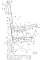
- a frame 30 On a base 10, for example a stadium stadium in cement, is fixed a frame 30, preferably a tubular metal structure.
- Two vertical side plates 35 reinforce the assembly being welded to the sockets 33, the beams 34 and the amounts 31.
- the seat itself On the slides 36 is mounted the seat itself, generally designated by the reference 20 and comprising a seat part 21 and a backrest 22.
- This seat 20 is advantageously constituted by a plastic shell molded.
- An intermediate frame 60 is provided on the one hand to give the seat good support for the weight of the person who occupies it, and on the other hand to support equipment as will be described later.
- This frame intermediate includes two elements 60 in general form of U comprising a lower branch 61 whose end rear is able to fit into a socket corresponding 33 of structure 30, and a branch upper 63 intended to engage over a length substantial in the associated hollow beam 34.
- a part of reference of the forces 62 connects the branches 61 and 62. It may for example be curved or straight and oblique.
- the seat 21 of the seat 20 has, as shown in Figure 7) two side edges descendants 21a inside which protrude profiled parts 21b intended to cooperate by complementary shapes with the slides 36 of the supporting structure 30.
- the seat 20 After installation of the seat by translation from from the front and engagement of the profiled parts 21b in the slides, the seat 20 is immobilized in place for example by screws or other tamper-evident pins which have illustrated axes A in Figure 5.
- the heads of these screws are provided with indentations for non-standard screwing.
- the undersides of the branches 61 of the frameworks intermediates 60 are also intended for fixing an element, generally designated by the reference 40 (see Figure 1) and defining a cable duct or ducts.
- This element 40 comprises an upper plate 45, for example of plastic or metal, extending from preferably continuously below a plurality of adjacent seats.
- This plate 45 is fixed under said branches 61 and retains an articulated receiving chute of cables or conduits which will be described later.
- This plate also delimits with the seat part 21 seats a space intended, as we will see more away, to house different kinds of equipment in a standard technical box.
- a profiled housing defined by two descending ribs spaced 45a, 45b (see Figure 5) and intended for attachment swivel of the chute. This forms a cover lower defining elongated compartments forming continuous paths for cables or conduits.
- This chute preferably made of material injected plastic common to a plurality of seats adjacent, includes a bottom 41, a rising front wall 43, a rising rear wall 44 and two members rising intermediates 42 extending from this bottom.
- three cable trays or conduits 46 can for example be assigned to electrical cables for strong currents, to electric cables for currents weak (audio, video, signaling, etc.) and to fluid conduits (hot air, cold air, hot water, water cold, ).
- the rear wall 44 of the chute has a sinuous part 44a intended to cooperate with the housing defined between the ribs 45a, 45b to produce the removable attachment and the pivoting of the chute, the rib 45a defining an end of travel stop during pivoting of the chute down.
- the articulated part of the chute is shown in dashed lines in the open position in Figure 5.
- this is preferably provided with either openings or parts thinned (sails) that can be easily pierced using of a tool.
- locking means in the closed position, not shown, for example of the snap type.
- a box shown in detail in Figures 1, 5, 6 and 10, which defines a space for example fitted out to receive technical equipment of standardized dimensions, for example to the 19 inch standard.
- Such a box in this case includes a part bottom provided with a bottom wall 51, walls lateral and a rear wall 53, a plate of upper closure 55 and a removable front cover 52 allowing the installation of equipment in the box.
- Such equipment is for example transducers sound such as an HP speaker with a T horn and directed towards the rear, the rear wall 53 being in this openwork case comprising fins 54 for diffusion sound.
- boxes 50 equipping the various seats are preferably mounted therein by making them just slide out like drawers from the front, the guidance being provided by the plates 35 and by secondary slides 37 (see FIG. 6) formed at the opposite of the slides 36 for the seat 20.
- the seat can be equipped with different tear-off detection devices or attempt to tear off. It can for example be strain gauges or microswitches, connected to a monitoring installation by cables running in one of the paths 46 of the chute 40.
- strain gauges or microswitches connected to a monitoring installation by cables running in one of the paths 46 of the chute 40.
- sensors 80, 81, 83 at level of assembly between backrest 22 and a backrest as will be described later, or again sensor 82 of the forced opening of the front cover 52 of the box 50.
- the seat can also have different locations of sensors such as microphones or detectors provided for security purposes, in particular metal detectors, volumetric packet detectors, etc.
- this equipment is connected to a central installation by cables laid in paths 46.
- the seat can be optionally fitted, at the top of its backrest 22 and on the rear side, a console 90 for the use of the occupant seated in the row immediately back.
- This console 90 can house different equipment, in particular a flat display screen 91, control or signaling keys, a microphone, a magnetic or microprocessor badge reader, a headphone socket, and more generally any connection appropriate, depending on the desired services.
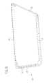
- this panel 23 is mounted in a recess of dimensions formed on the back of the backrest 22.
- a backrest 24 provided with an opening 25 of dimensions is attached and fixed, for example using security screws with non-standard fingerprints, the back of the backrest 22 so as to trap the panel 23 in an inviolable manner.
- Backrest 22 and backrest 24 are in this case suitable for defining protected cable passages or conduits, which can enter it for example via one or several openings 26 formed at the base of the counterplate 24. It is of course also possible to provide cable or conduit passages under the seat.
- the assembly can be engaged in a defined space of appropriately inside the folder via an opening upper, according to arrow F.
- the frame 124 is guided there by two lateral slides 127.
- the advertising panel 23 is front / back, and the front and back walls of the backrest 22 both have dimensioned openings corresponding.
- a locking device 126 with key or analogous, of the panel 23 in its housing.
- an advertising panel can be provided at console 90.
- Arrangement of the backrest to receive a panel advertising can be planned completely independently of device for passing cables or conduits in accordance with present invention.
- mounting the seat by slides on a support structure can also be provided totally regardless of the cable routing device or conduits according to the present invention.
- a seat of a row of seats according to the invention is equipped with two sound diffusers.
- a first diffuser 100 provided with a bent roof 101 is housed in the seat shell, the lower half-shell 29 being appropriately shaped.
- Pavilion 101 opens onto a perforated wall constituting the wall rear of seat back 22.
- the second diffuser 110 is provided in a box 120 provided below the seat and defining a compartment 121.
- This diffuser comprises a pavilion 111 curved towards the front so as to diffuse the sound through the wall perforated front of the box.
- the cables are in this case housed in 400 tubes extending along the seats.
- the chute 40 for cables or conduits is incorporated into the seat 21 of the seat. More specifically, the chute 40 is fixedly mounted on a support which can be any, being part of a lower half-shell of the seat. Access to the chute can be achieved either by opening it downwards by pivoting, as described above, in the case where the support structure allows, either by removing or tilting the upper half-shell of the seat.
- the passage for cables or conduits is defined by a frame element 141 U-shaped, able to open backwards by removing a closing hatch 143.
- each component of a seat according to the invention can be carried out in step from the seat, and the elements involved in making the cable tray or closed conduits can be joined to each other when the seats are mounted side by side to others, so as to form continuous pieces or substantially continuous when assembling the seats adjacent.
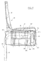
- Figures 17 to 19 thus illustrate a seat mounted on a frame 30 and comprising a seat element 20 with a seat 21 and a backrest 22.
- the trunking element consists of a part a substantially parallelepipedic box 240 produced in two superimposed halves 241 and 242.
- the element forming seat has on each side at the base of its falling edge 21a, one wing 21b projecting horizontally outwards.
- the box 240 comprises on each side a wing projecting horizontally towards the exterior and constituted by two superimposed members 241a, 242a of the two parts of the cabinet.
- the framework 30 comprises, at the level of a hollow beam square cantilever 34, an insert 37, produced in folded and welded sheet metal on the outer flank of the tube 34, this part defining the slide 36 for the seat 20 between a flange 39 and the upper face of the beam 34, and defining another slide for the box 240 at another re-entrant edge 38 located below beam 34.
- each half box has a hollow lateral appendage 244, of section transverse in general shape of "U", the appendages of two adjacent cabinets being sized to meet as shown in figure 20.
- the rear part of the 240 box can be used to house all types of equipment, in the same way as the box 50 described above, and in particular equipment of sound diffusion.
- This device illustrated in detail in FIGS. 22 to 27 and generally designated by the reference 150 includes a frame member 152 of shaped cross section general of "U" returned, whose outer section is slightly smaller than the inner section of the tube square 34 of the seat mounting frame.
- This item 152 is integral with a vertical plate 151 dimensioned, in particularly vertically, so that the device 150 being in position, it covers and seals slides 36 and 38, after the box 240 and the seat element 20 have been put in place.
- a cam 153 Between the two lateral branches of the element frame 152 is pivotally mounted around a transverse horizontal axis, a cam 153.
- This cam has a through bore 155 defined by a portion forming bearing 156, a part with toothed eccentric face 154, and a straight face 157.
- the plate 151 and a face front of the frame member 152 are crossed by a threaded bore into which can be engaged horizontally and axially a locking screw 158 capable of come to rest against the right face 157
- the device 150 is locked in engaging the frame part 152 in the opening end of the tube 34, until the plate 151 comes in abutment against this end.
- the screw 158 is then screwed, which has the effect of press cam 153 clockwise shows that figure 22, and to anchor the teeth of the face eccentric 154 in the bottom wall of the tube 34.
- Figures 24 and 25 show a tool for allow the device 150 to be unlocked.
- This tool generally indicated in 160, includes a handle 161, a rod 162 ending in a hinge 163 on which is mounted a rod 164 ending at its free end by a roller 165.
- Unlocking is carried out by engaging the tool 160 in the space between cam 153 and the wall upper part of frame 152. Rod 164 and its roller 165 are then guided downwards by the tongue 159 and, relying on the latter, will be able to request the cam 153 counterclockwise watch for unlocking.
- Screw 158 must of course be partially unscrewed or removed.
Landscapes
- Health & Medical Sciences (AREA)
- Dentistry (AREA)
- General Health & Medical Sciences (AREA)
- Installation Of Indoor Wiring (AREA)
- Seats For Vehicles (AREA)
- Multi-Conductor Connections (AREA)
- Insulated Conductors (AREA)
- Details Of Indoor Wiring (AREA)
- Chair Legs, Seat Parts, And Backrests (AREA)
- Chairs For Special Purposes, Such As Reclining Chairs (AREA)
- Passenger Equipment (AREA)
Claims (14)
- Reihe aus mindestens zwei Sitzen, von dem Typ, der folgendes umfaßt: eine Abstützungsstruktur (30), Elemente, die Sitze (20) bilden, die auf der Abstützungsstruktur angebracht sind, sowie einen Durchlaß für Kabel oder Leitungen (46), der der Abstützung zugeordnet ist, dadurch gekennzeichnet, daß der genannte Durchlaß für Kabel oder Leitungen durch eine Rinne (40; 140) definiert ist, die sich längs einer Vielzahl von Sitzen erstreckt und dazu eingerichtet ist, im wesentlichen auf der ganzen Länge ihrer Erstreckung für den Zugang zum Einlegen und Entnehmen von Kabeln oder Leitungen geöffnet zu werden.
- Sitzreihe nach Anspruch 1, dadurch gekennzeichnet, daß der genannte Durchlaß (46) gemeinsam durch ein oberes, festes Element (45; 21) und durch ein angesetztes Element (40) definiert ist, das die genannte Rinne bildet und dazu eingerichtet ist, zu seinem Öffnen nach unten sowie zu seinem Schließen gegen das feste Element nach oben zurückgeschlagen zu werden.
- Sitzreihe nach Anspruch 2, dadurch gekennzeichnet, daß die genannte Rinne eine Vielzahl von Unterteilungen (46) aufweist, die nach oben offen sind und dazu eingerichtet sind, Leitungen oder Kabel unterschiedlicher Natur aufzunehmen.
- Sitzreihe nach einem der Ansprüche 2 und 3, dadurch gekennzeichnet, daß die genannte Rinne (40) gelenkig angebracht ist.
- Sitzreihe nach einem der Ansprüche 1 bis 4, dadurch gekennzeichnet, daß mindestens einer der Sitze einen Kasten (50, 240) aufweist, der ein technisches Fach bildet, das durch Einschieben zwischen der Sitzfläche (21) des Sitzes und der genannten Rinne (40) angebracht ist.
- Sitzreihe nach Anspruch 5, dadurch gekennzeichnet, daß jeder Sitz einen Kasten (240) aufweist, und daß die Rinne durch einen Bereich eines jeden Kastens definiert ist.
- Sitzreihe nach Anspruch 6, dadurch gekennzeichnet, daß jeder Kasten einen seitlichen, hohlen Anhang (244) aufweist, und daß zwei benachbarte Anhänge zwischen zwei Kästen eine kontinuierliche Fortsetzung der Rinne sicherstellen.
- Sitzreihe nach einem der Ansprüche 6 und 7, dadurch gekennzeichnet, daß jeder Kasten mit zwei übereinanderliegenden Teilen (241, 242) ausgebildet ist und durch Einschieben in Gleitführungen (38) unter der Sitzfläche (21) des Elements angebracht ist, das den zugeordneten Sitz bildet.
- Sitzreihe nach Anspruch 8, dadurch gekennzeichnet, daß jedes Element, das einen Sitz (20) bildet, einen vorderen, abfallenden Rand (21c) besitzt, der den zugeordneten Kasten (240) in seiner Lage verriegelt.
- Sitzreihe nach einem der Ansprüche 8 und 9, dadurch gekennzeichnet, daß jedes, einen Sitz (20) bildende Element auf der genannten Abstützungsstruktur (30) durch Einschieben in Gleitführungen (36) im wesentlichen parallel zur Einschieberichtung des Kastens (240) angebracht ist, und daß mindestens eine Verriegelungsvorrichtung (150) vorgesehen ist, um jedes einen Sitz bildende Element nach der Anbringung gegenüber dem Verschieben festzulegen.
- Sitzreihe nach Anspruch 10, dadurch gekennzeichnet, daß die Verriegelungsvorrichtung ein Verriegelungselement (151, 152) mit drehbarem Nocken (153) aufweist, der in Eingriff in ein freies Ende eines hohlen Rohrelements (34) der Abstützungsstruktur steht, und daß das Verriegelungselement die Enden der Gleitführungen abdeckt, wobei eine Zugwirkung am genannten Verriegelungselement ein Hervortreten des Nockens (153) in Querrichtung zum Rohrelement hervorruft.
- Sitzreihe nach einem der Ansprüche 1 bis 11, dadurch gekennzeichnet, daß sie Einrichtungen aufweist, die in der Gruppe ausgewählt sind, die Sicherheitsfühler (80-83) und Mittel zur Schallausbreitung (HP, T) aufweisen.
- Sitzreihe nach einem der Ansprüche 1 bis 12, dadurch gekennzeichnet, daß in der Rückenlehne (22) mindestens eines Sitzes mindestens eine Aufnahme für einen Bildträger (23) vorgesehen ist.
- Sitzreihe nach Anspruch 13, dadurch gekennzeichnet, daß der oder die Bildträger (22) vorne und hinten betrachtbar ist bzw. sind, und daß die Rückenlehne eine vordere und eine hintere Öffnung zum Betrachten des Trägers aufweist.
Applications Claiming Priority (3)
| Application Number | Priority Date | Filing Date | Title |
|---|---|---|---|
| FR9605792A FR2748376B1 (fr) | 1996-05-09 | 1996-05-09 | Rangee de sieges equipes de moyens de passage de cables ou conduits |
| FR9605792 | 1996-05-09 | ||
| PCT/FR1997/000832 WO1997042858A1 (fr) | 1996-05-09 | 1997-05-09 | Rangee de sieges equipes de moyens de passage de cables ou conduits |
Publications (2)
| Publication Number | Publication Date |
|---|---|
| EP0910261A1 EP0910261A1 (de) | 1999-04-28 |
| EP0910261B1 true EP0910261B1 (de) | 2001-03-21 |
Family
ID=9491979
Family Applications (1)
| Application Number | Title | Priority Date | Filing Date |
|---|---|---|---|
| EP97924071A Expired - Lifetime EP0910261B1 (de) | 1996-05-09 | 1997-05-09 | Stuhlreihe mit kabel- oder kanalführungen |
Country Status (10)
| Country | Link |
|---|---|
| EP (1) | EP0910261B1 (de) |
| AT (1) | ATE199818T1 (de) |
| AU (1) | AU2966197A (de) |
| CA (1) | CA2289581C (de) |
| DE (1) | DE69704354T2 (de) |
| ES (1) | ES2157577T3 (de) |
| FR (1) | FR2748376B1 (de) |
| GR (1) | GR3036087T3 (de) |
| PT (1) | PT910261E (de) |
| WO (1) | WO1997042858A1 (de) |
Families Citing this family (3)
| Publication number | Priority date | Publication date | Assignee | Title |
|---|---|---|---|---|
| WO2002032268A1 (en) * | 2000-10-20 | 2002-04-25 | William Ashley Donlan | Seat signage and associated sales systems |
| ES2186582B1 (es) * | 2001-10-19 | 2004-08-16 | Francisco Prieto Molina | Banco para asiento con sistemas de distribucion electricos o electronicos. |
| US10801216B1 (en) * | 2019-05-20 | 2020-10-13 | MSG Sports and Entertainment, LLC | System for distributing wireless networking components in a venue |
Family Cites Families (3)
| Publication number | Priority date | Publication date | Assignee | Title |
|---|---|---|---|---|
| AU2640277A (en) * | 1976-07-05 | 1979-01-04 | Castelli Sas Anonima | Auditorium chairs |
| US4255610A (en) * | 1978-05-03 | 1981-03-10 | Gf Business Equipment, Inc. | Partition wiring system |
| IT1202482B (it) * | 1987-02-06 | 1989-02-09 | Canalplast Srl | Sistema di elementi modulari,per la realizzazione di canalizzazioni per cavi elettrici e simili |
-
1996
- 1996-05-09 FR FR9605792A patent/FR2748376B1/fr not_active Expired - Fee Related
-
1997
- 1997-05-09 PT PT97924071T patent/PT910261E/pt unknown
- 1997-05-09 WO PCT/FR1997/000832 patent/WO1997042858A1/fr not_active Ceased
- 1997-05-09 EP EP97924071A patent/EP0910261B1/de not_active Expired - Lifetime
- 1997-05-09 ES ES97924071T patent/ES2157577T3/es not_active Expired - Lifetime
- 1997-05-09 DE DE69704354T patent/DE69704354T2/de not_active Expired - Fee Related
- 1997-05-09 AU AU29661/97A patent/AU2966197A/en not_active Abandoned
- 1997-05-09 CA CA002289581A patent/CA2289581C/fr not_active Expired - Lifetime
- 1997-05-09 AT AT97924071T patent/ATE199818T1/de not_active IP Right Cessation
-
2001
- 2001-06-19 GR GR20010400932T patent/GR3036087T3/el not_active IP Right Cessation
Also Published As
| Publication number | Publication date |
|---|---|
| PT910261E (pt) | 2001-09-28 |
| ATE199818T1 (de) | 2001-04-15 |
| FR2748376B1 (fr) | 1998-07-31 |
| ES2157577T3 (es) | 2001-08-16 |
| DE69704354T2 (de) | 2001-10-31 |
| FR2748376A1 (fr) | 1997-11-14 |
| GR3036087T3 (en) | 2001-09-28 |
| WO1997042858A1 (fr) | 1997-11-20 |
| DE69704354D1 (de) | 2001-04-26 |
| AU2966197A (en) | 1997-12-05 |
| CA2289581C (fr) | 2005-03-22 |
| CA2289581A1 (fr) | 1997-11-20 |
| EP0910261A1 (de) | 1999-04-28 |
Similar Documents
| Publication | Publication Date | Title |
|---|---|---|
| BE1010215A4 (fr) | Dispositif pour la presentation de documents. | |
| EP0910261B1 (de) | Stuhlreihe mit kabel- oder kanalführungen | |
| EP0651482B1 (de) | Trägervorrichtung für elektrische Geräte | |
| CA2089447C (fr) | Volet sous porte-bagages pour salle voyageurs d'un vehicule ferroviaire | |
| FR2677066A1 (fr) | Salle de representation itinerante. | |
| EP2157360A1 (de) | Staubdichter Reliefkasten | |
| EP1558825B1 (de) | Komposit-unterdecke mit aufgespannter leinwand | |
| FR2499016A1 (fr) | Installation de rangement d'ustensiles | |
| FR3062865A1 (fr) | Procede de montage d'un revetement souple tendu sur un cadre de fixation et cadre de fixation pour la mise en oeuvre dudit procede | |
| FR2733531A1 (fr) | Salle de representation et/ou de projection itinerante | |
| FR2461801A1 (fr) | Porte sectionnelle isolante | |
| FR3033743A1 (fr) | Vehicule comportant un volume de chargement accessible par des portes battantes laterale et transversale et un toit pivotant | |
| FR2967184A1 (fr) | Kit d'habillage pour un systeme d'enroulement d'une couverture de piscine | |
| FR2733805A1 (fr) | Panneau d'affichage constitue d'une toile tendue sur un cadre | |
| EP2662510A2 (de) | Provisorischer Laden oder Kommunikationsstand und/oder zum Verkauf | |
| EP0057798B1 (de) | Bauteil oder Wand für die Ausstattung eines öffentlichen Lokals | |
| FR3161917A1 (fr) | Système de sécurisation amovible en kit d’une baie d’un mur | |
| FR2715685A1 (fr) | Abri amovible pour la couverture de surfaces à protéger. | |
| FR2644965A3 (fr) | Boite modulaire pour elements electriques | |
| FR2497452A1 (fr) | Batterie de boites aux lettres, a ouverture totale | |
| FR2700933A1 (fr) | Casier de rangement et modules de casiers de rangement formant vestiaire par exemple. | |
| BE1017034A6 (fr) | Systeme de superstructure fixee en applique murale, pour montage, en circonstances particulieres, de portes metalliques. | |
| FR2622365A1 (fr) | Boitier pour l'equipement d'une armoire de distribution d'energie electrique | |
| FR2779470A1 (fr) | Dispositif de protection de la fixation d'un tableau ou similaire sur un mur | |
| WO1998000310A1 (fr) | Salle de representation et/ou de projection itinerante |
Legal Events
| Date | Code | Title | Description |
|---|---|---|---|
| PUAI | Public reference made under article 153(3) epc to a published international application that has entered the european phase |
Free format text: ORIGINAL CODE: 0009012 |
|
| 17P | Request for examination filed |
Effective date: 19981207 |
|
| AK | Designated contracting states |
Kind code of ref document: A1 Designated state(s): AT BE CH DE DK ES FI FR GB GR IE IT LI LU MC NL PT SE |
|
| AX | Request for extension of the european patent |
Free format text: RO PAYMENT 19981209 |
|
| GRAG | Despatch of communication of intention to grant |
Free format text: ORIGINAL CODE: EPIDOS AGRA |
|
| 17Q | First examination report despatched |
Effective date: 20000523 |
|
| GRAG | Despatch of communication of intention to grant |
Free format text: ORIGINAL CODE: EPIDOS AGRA |
|
| GRAH | Despatch of communication of intention to grant a patent |
Free format text: ORIGINAL CODE: EPIDOS IGRA |
|
| GRAH | Despatch of communication of intention to grant a patent |
Free format text: ORIGINAL CODE: EPIDOS IGRA |
|
| GRAA | (expected) grant |
Free format text: ORIGINAL CODE: 0009210 |
|
| AK | Designated contracting states |
Kind code of ref document: B1 Designated state(s): AT BE CH DE DK ES FI FR GB GR IE IT LI LU MC NL PT SE |
|
| AX | Request for extension of the european patent |
Free format text: RO PAYMENT 19981209 |
|
| PG25 | Lapsed in a contracting state [announced via postgrant information from national office to epo] |
Ref country code: FI Free format text: LAPSE BECAUSE OF FAILURE TO SUBMIT A TRANSLATION OF THE DESCRIPTION OR TO PAY THE FEE WITHIN THE PRESCRIBED TIME-LIMIT Effective date: 20010321 |
|
| REF | Corresponds to: |
Ref document number: 199818 Country of ref document: AT Date of ref document: 20010415 Kind code of ref document: T |
|
| REG | Reference to a national code |
Ref country code: CH Ref legal event code: EP |
|
| REG | Reference to a national code |
Ref country code: IE Ref legal event code: FG4D Free format text: FRENCH |
|
| REF | Corresponds to: |
Ref document number: 69704354 Country of ref document: DE Date of ref document: 20010426 |
|
| PG25 | Lapsed in a contracting state [announced via postgrant information from national office to epo] |
Ref country code: LU Free format text: LAPSE BECAUSE OF NON-PAYMENT OF DUE FEES Effective date: 20010509 |
|
| ITF | It: translation for a ep patent filed | ||
| PG25 | Lapsed in a contracting state [announced via postgrant information from national office to epo] |
Ref country code: SE Free format text: LAPSE BECAUSE OF FAILURE TO SUBMIT A TRANSLATION OF THE DESCRIPTION OR TO PAY THE FEE WITHIN THE PRESCRIBED TIME-LIMIT Effective date: 20010621 Ref country code: DK Free format text: LAPSE BECAUSE OF FAILURE TO SUBMIT A TRANSLATION OF THE DESCRIPTION OR TO PAY THE FEE WITHIN THE PRESCRIBED TIME-LIMIT Effective date: 20010621 |
|
| REG | Reference to a national code |
Ref country code: CH Ref legal event code: NV Representative=s name: MICHELI & CIE INGENIEURS-CONSEILS |
|
| GBT | Gb: translation of ep patent filed (gb section 77(6)(a)/1977) |
Effective date: 20010614 |
|
| REG | Reference to a national code |
Ref country code: ES Ref legal event code: FG2A Ref document number: 2157577 Country of ref document: ES Kind code of ref document: T3 |
|
| REG | Reference to a national code |
Ref country code: PT Ref legal event code: SC4A Free format text: AVAILABILITY OF NATIONAL TRANSLATION Effective date: 20010620 |
|
| REG | Reference to a national code |
Ref country code: GB Ref legal event code: IF02 |
|
| PLBE | No opposition filed within time limit |
Free format text: ORIGINAL CODE: 0009261 |
|
| STAA | Information on the status of an ep patent application or granted ep patent |
Free format text: STATUS: NO OPPOSITION FILED WITHIN TIME LIMIT |
|
| 26N | No opposition filed | ||
| PGFP | Annual fee paid to national office [announced via postgrant information from national office to epo] |
Ref country code: PT Payment date: 20030513 Year of fee payment: 7 |
|
| PGFP | Annual fee paid to national office [announced via postgrant information from national office to epo] |
Ref country code: GR Payment date: 20030530 Year of fee payment: 7 Ref country code: NL Payment date: 20030530 Year of fee payment: 7 Ref country code: DE Payment date: 20030530 Year of fee payment: 7 Ref country code: AT Payment date: 20030530 Year of fee payment: 7 |
|
| PGFP | Annual fee paid to national office [announced via postgrant information from national office to epo] |
Ref country code: IE Payment date: 20030603 Year of fee payment: 7 |
|
| PGFP | Annual fee paid to national office [announced via postgrant information from national office to epo] |
Ref country code: MC Payment date: 20030605 Year of fee payment: 7 Ref country code: CH Payment date: 20030605 Year of fee payment: 7 |
|
| PGFP | Annual fee paid to national office [announced via postgrant information from national office to epo] |
Ref country code: BE Payment date: 20030715 Year of fee payment: 7 |
|
| PG25 | Lapsed in a contracting state [announced via postgrant information from national office to epo] |
Ref country code: AT Free format text: LAPSE BECAUSE OF NON-PAYMENT OF DUE FEES Effective date: 20040509 |
|
| PG25 | Lapsed in a contracting state [announced via postgrant information from national office to epo] |
Ref country code: IE Free format text: LAPSE BECAUSE OF NON-PAYMENT OF DUE FEES Effective date: 20040510 |
|
| PG25 | Lapsed in a contracting state [announced via postgrant information from national office to epo] |
Ref country code: MC Free format text: LAPSE BECAUSE OF NON-PAYMENT OF DUE FEES Effective date: 20040531 Ref country code: LI Free format text: LAPSE BECAUSE OF NON-PAYMENT OF DUE FEES Effective date: 20040531 Ref country code: CH Free format text: LAPSE BECAUSE OF NON-PAYMENT OF DUE FEES Effective date: 20040531 Ref country code: BE Free format text: LAPSE BECAUSE OF NON-PAYMENT OF DUE FEES Effective date: 20040531 |
|
| PG25 | Lapsed in a contracting state [announced via postgrant information from national office to epo] |
Ref country code: PT Free format text: LAPSE BECAUSE OF NON-PAYMENT OF DUE FEES Effective date: 20041109 |
|
| BERE | Be: lapsed |
Owner name: *BUJON DANIEL Effective date: 20040531 Owner name: *CHATAIGNIER BERNARD Effective date: 20040531 |
|
| PG25 | Lapsed in a contracting state [announced via postgrant information from national office to epo] |
Ref country code: NL Free format text: LAPSE BECAUSE OF NON-PAYMENT OF DUE FEES Effective date: 20041201 Ref country code: DE Free format text: LAPSE BECAUSE OF NON-PAYMENT OF DUE FEES Effective date: 20041201 |
|
| PG25 | Lapsed in a contracting state [announced via postgrant information from national office to epo] |
Ref country code: GR Free format text: LAPSE BECAUSE OF NON-PAYMENT OF DUE FEES Effective date: 20041203 |
|
| REG | Reference to a national code |
Ref country code: CH Ref legal event code: PL |
|
| REG | Reference to a national code |
Ref country code: PT Ref legal event code: MM4A Effective date: 20041109 |
|
| NLV4 | Nl: lapsed or anulled due to non-payment of the annual fee |
Effective date: 20041201 |
|
| REG | Reference to a national code |
Ref country code: IE Ref legal event code: MM4A |
|
| PGFP | Annual fee paid to national office [announced via postgrant information from national office to epo] |
Ref country code: ES Payment date: 20080625 Year of fee payment: 12 |
|
| PGFP | Annual fee paid to national office [announced via postgrant information from national office to epo] |
Ref country code: IT Payment date: 20080530 Year of fee payment: 12 |
|
| PGFP | Annual fee paid to national office [announced via postgrant information from national office to epo] |
Ref country code: GB Payment date: 20080620 Year of fee payment: 12 |
|
| GBPC | Gb: european patent ceased through non-payment of renewal fee |
Effective date: 20090509 |
|
| PG25 | Lapsed in a contracting state [announced via postgrant information from national office to epo] |
Ref country code: GB Free format text: LAPSE BECAUSE OF NON-PAYMENT OF DUE FEES Effective date: 20090509 |
|
| REG | Reference to a national code |
Ref country code: ES Ref legal event code: FD2A Effective date: 20090511 |
|
| PG25 | Lapsed in a contracting state [announced via postgrant information from national office to epo] |
Ref country code: ES Free format text: LAPSE BECAUSE OF NON-PAYMENT OF DUE FEES Effective date: 20090511 |
|
| PG25 | Lapsed in a contracting state [announced via postgrant information from national office to epo] |
Ref country code: IT Free format text: LAPSE BECAUSE OF NON-PAYMENT OF DUE FEES Effective date: 20090509 |
|
| REG | Reference to a national code |
Ref country code: FR Ref legal event code: PLFP Year of fee payment: 20 |
|
| PGFP | Annual fee paid to national office [announced via postgrant information from national office to epo] |
Ref country code: FR Payment date: 20160513 Year of fee payment: 20 |