EP0909949A2 - Capteur pour mesurer la conductibilité électrique d'un milieu liquide - Google Patents
Capteur pour mesurer la conductibilité électrique d'un milieu liquide Download PDFInfo
- Publication number
- EP0909949A2 EP0909949A2 EP98119644A EP98119644A EP0909949A2 EP 0909949 A2 EP0909949 A2 EP 0909949A2 EP 98119644 A EP98119644 A EP 98119644A EP 98119644 A EP98119644 A EP 98119644A EP 0909949 A2 EP0909949 A2 EP 0909949A2
- Authority
- EP
- European Patent Office
- Prior art keywords
- electrodes
- circuit board
- sensor according
- probe body
- recess
- Prior art date
- Legal status (The legal status is an assumption and is not a legal conclusion. Google has not performed a legal analysis and makes no representation as to the accuracy of the status listed.)
- Granted
Links
Images
Classifications
-
- G—PHYSICS
- G01—MEASURING; TESTING
- G01N—INVESTIGATING OR ANALYSING MATERIALS BY DETERMINING THEIR CHEMICAL OR PHYSICAL PROPERTIES
- G01N27/00—Investigating or analysing materials by the use of electric, electrochemical, or magnetic means
- G01N27/02—Investigating or analysing materials by the use of electric, electrochemical, or magnetic means by investigating impedance
- G01N27/04—Investigating or analysing materials by the use of electric, electrochemical, or magnetic means by investigating impedance by investigating resistance
- G01N27/06—Investigating or analysing materials by the use of electric, electrochemical, or magnetic means by investigating impedance by investigating resistance of a liquid
- G01N27/08—Investigating or analysing materials by the use of electric, electrochemical, or magnetic means by investigating impedance by investigating resistance of a liquid which is flowing continuously
-
- G—PHYSICS
- G01—MEASURING; TESTING
- G01N—INVESTIGATING OR ANALYSING MATERIALS BY DETERMINING THEIR CHEMICAL OR PHYSICAL PROPERTIES
- G01N27/00—Investigating or analysing materials by the use of electric, electrochemical, or magnetic means
- G01N27/02—Investigating or analysing materials by the use of electric, electrochemical, or magnetic means by investigating impedance
- G01N27/04—Investigating or analysing materials by the use of electric, electrochemical, or magnetic means by investigating impedance by investigating resistance
- G01N27/06—Investigating or analysing materials by the use of electric, electrochemical, or magnetic means by investigating impedance by investigating resistance of a liquid
- G01N27/07—Construction of measuring vessels; Electrodes therefor
Definitions
- the invention relates to a transducer for detection the electrical conductivity of a liquid medium.
- Such sensors are in many Executions known. So is from EP-A-0 386 660 Sensor for measuring the conductivity of a fluid known in which several electrodes in the form of Metal rings on an end face of a cylindrical Probe body are arranged.
- DE-A-2802 182 describes a measuring device for measuring the electrical resistance of a liquid with several plate-shaped electrodes in a common Envelope cylinders are arranged. From EP-A-0 193 015 it is known, with a sensor for measuring the electrical Conductivity for monitoring combustion processes at least two electrodes with leads in the form of Conductor tracks on an insulating, heat and arrange corrosion-resistant substrate and the Supply lines with the exception of the contact points with a heat and / or corrosion resistant dielectric to cover.
- EP-B-0 113 427 describes an electrical measuring probe for Detect the electrical conductivity of a liquid Measured material, electrodes for forming an in Probe longitudinal direction provided by the measured material is flowed through, together with shielded from the measured material electrical leads a mechanically stabilizing and electroconductive lead frame one the shape of the Form the probe-defining envelope, which consists of thermoplastic injection molding is made.
- a similar probe is also in DE 30 06 877 described.
- the invention has for its object a Transducer for recording the electrical To create conductivity of a liquid medium in which with a comparatively simple, but nevertheless stable Structure of the device through the stray field of the measuring section external influences as well as the type of installation and the Position in a container holding the medium or in the Flow of the medium is influenced as little as possible without that additional shielding must be provided.
- the transducer according to the invention enables a high largely independent of external influences Accuracy in measuring the conductivity of a liquid medium. It is inexpensive to manufacture and also keeps a relatively mild treatment in the Operation stopped permanently.
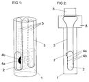
- the embodiment shown in Figs. 1 and 2 transducer according to the invention consists of a Probe body 1 made by a block of electrical insulating plastic is formed and a cylindrical or rod-shaped elongated shape with circular or has an oval cross-section.
- a Probe body 1 made by a block of electrical insulating plastic is formed and a cylindrical or rod-shaped elongated shape with circular or has an oval cross-section.
- he has one in a lower area Longitudinal axis of the probe body 1 radially extending Recess 2, the one open at both ends, through the Forms probe body 1 extending channel.
- a radially projecting end piece 8 formed, which is only shown in Fig. 2 and to can serve the transducer in a possibly provided larger measuring device or in a Storage or attach storage device.
- radially protruding End piece can also be disregarded if necessary.
- the radially projecting end piece 8 in to provide a handle, not shown in the drawings, with which the transducer is placed into liquid medium by hand used and held therein for the duration of the measurement can be.
- each has a pair of electrodes 4a, 4b in mutual distance parallel to each other so that the electrodes 4a and 4b of the two Pairs of electrodes in the recess 2 each face each other.
- Each of the two pairs of electrodes 4a, 4b consists of a ring-shaped outer electrode 4a and a disc-shaped inner electrode 4b which is formed by the annular outer electrode 4a while maintaining a intermediate distance is surrounded.
- the two lateral surfaces are preferably the Recess that face each other at a distance, at least in the direction of the central longitudinal axis of the Recess so large that they protrude beyond the area, the electrodes 4a, 4b of the two pairs of electrodes occupy these lateral surfaces of the recess 2. This ensures that the outer ring electrodes 4a of the two pairs of electrodes at their edges certain minimum distance to an inner wall surface of a the liquid medium receiving container or Guide channel or another inner surface in this Maintain container or guide channel, even if the Sensor is inserted into the medium in such a way that the special body 1 this inner wall surface or other Touches the inner surface of the container or guide channel.
- each pair of electrodes 4a, 4b are each connected to conductor tracks 5, which on surfaces of Circuit board 3 arranged and in the circuit board are embedded so that they are from the printed circuit board 3 are encased on all sides.
- the contact tracks 5 lead in the 1 and 2 upwards and are there a connector 6 connected to the top of the probe body 1 and shown only in Fig. 2 is.
- the conductor tracks 5 are on the one hand to the respective Electrodes 4a and 4b and on the other hand to the Connector 6 connected such that when connected an external voltage source, not shown, and an external electrical, also not shown Measuring device to the connector 6, the annular outer Electrodes 4a of the two pairs of electrodes with the aforementioned voltage source are connected while the disc-shaped inner electrodes 4b of the two Electrode pairs are on the aforementioned measuring device. Consequently are the annular outer electrodes 4a than that Electrodes with the larger cross section than current electrodes switched while the disc-shaped inner electrodes than the electrodes with the smaller cross section than Voltage electrodes are used with which the voltage drop practical in the medium acting as a resistance measured without power and thus the conductivity of the Medium is determined.
- gold-coated electrodes 4a, 4b when the flexible printed circuit board 3 is subjected to bending stress can avoid the circuit board in the area of the electrodes on the back covered with rigid plates, which have approximately the size of the respective pair of electrodes.
- a conductometer is preferably used as the measuring device.
- the electrodes 4a, 4b of the two pairs of electrodes are each provided with an electrically conductive coating, which has a higher electrical normal potential, d. H. is more noble than the conductor material of the conductor tracks 5.
- An insulation coating applied to the printed circuit board 3 covers the conductor tracks 5 with the exception of those in the area of Connector 6 trained contact points and leaves the electrodes 4a, 4b of the electrode pairs are also free.
- circuit board 3 is also in the Area of the recess 2 as a resistance thermometer or temperature sensor acting temperature-dependent Resistor 7, which is only shown in Fig. 2 and over not separately shown, arranged on the printed circuit board 3 Conductor tracks also at connector 6 connected.
- the circuit board 3 and the electrical arranged thereon Components are made of the plastic material of the probe body 1 envelops, but the area of the electrodes 4a, 4b two pairs of electrodes and the area of the temperature-dependent resistor 7 with the inside of the Recess 2 exposed surfaces exposed.
- the probe body 1 is molded in the injection molding process, the circuit board 3 with those arranged on it electrical components as well as the connector 6 are injected into the probe body 1. This eliminates the need a separate assembly and mechanical connection of the Printed circuit board 3 and the connector 6 with the Probe body 1.
- the stray field between the two pairs of electrodes lying measuring section lies within the sensor, so that an adverse influence of external disturbances on the Field is low. Additional shielding devices are therefore unnecessary.
- a possible dependence of the measurement result on the Temperature of the respective medium at the Conductivity is determined by the temperature-dependent Resistor 7 compensated.
- the free end parts of the U-shaped circuit board can be superimposed parallel to each other, such as this is shown in Fig. 2, or from the top protruding surface of the probe body 1 (not shown) in order to make contact with the connector 6 to be connected.
- U-shaped circuit board 13 can in not shown in detail, also two separate, PCBs arranged parallel to one another are provided that are arranged similarly to the two Leg of the U-shaped shown in Figs. 1 and 2 PCB 3.
- Such an arrangement also enables a division of the probe body 1 into two symmetrical sub-bodies that with axially parallel surfaces along an axially parallel one Level, preferably the level of symmetry, can be put together are (not shown in the drawings).
- Level preferably the level of symmetry
- Such a construction enables a particularly simple one Maintenance of the electrodes by temporarily loosening the two sub-bodies of the probe body 1 from each other, whereby unhindered access to the electrodes for Cleaning purposes etc. is possible.
- circuit board 3 On the circuit board 3 or on several circuit boards of the Transducer can also have additional active or passive circuit elements are arranged, e.g. B. Preamplifier and / or circuit elements for the Signal separation or other signal processing (in the Drawings not shown).
- additional active or passive circuit elements e.g. B. Preamplifier and / or circuit elements for the Signal separation or other signal processing (in the Drawings not shown).
Landscapes
- Chemical & Material Sciences (AREA)
- Chemical Kinetics & Catalysis (AREA)
- Electrochemistry (AREA)
- Physics & Mathematics (AREA)
- Health & Medical Sciences (AREA)
- Life Sciences & Earth Sciences (AREA)
- Analytical Chemistry (AREA)
- Biochemistry (AREA)
- General Health & Medical Sciences (AREA)
- General Physics & Mathematics (AREA)
- Immunology (AREA)
- Pathology (AREA)
- Investigating Or Analyzing Materials By The Use Of Electric Means (AREA)
- Measurement Of Resistance Or Impedance (AREA)
Applications Claiming Priority (2)
| Application Number | Priority Date | Filing Date | Title |
|---|---|---|---|
| DE19746075A DE19746075C2 (de) | 1997-10-17 | 1997-10-17 | Meßwertaufnehmer zur Erfassung der elektrischen Leitfähigkeit eines flüssigen Mediums |
| DE19746075 | 1997-10-17 |
Publications (3)
| Publication Number | Publication Date |
|---|---|
| EP0909949A2 true EP0909949A2 (fr) | 1999-04-21 |
| EP0909949A3 EP0909949A3 (fr) | 1999-06-23 |
| EP0909949B1 EP0909949B1 (fr) | 2003-02-12 |
Family
ID=7845933
Family Applications (1)
| Application Number | Title | Priority Date | Filing Date |
|---|---|---|---|
| EP98119644A Expired - Lifetime EP0909949B1 (fr) | 1997-10-17 | 1998-10-16 | Capteur pour mesurer la conductibilité électrique d'un milieu liquide |
Country Status (3)
| Country | Link |
|---|---|
| EP (1) | EP0909949B1 (fr) |
| AT (1) | ATE232603T1 (fr) |
| DE (2) | DE19746075C2 (fr) |
Cited By (4)
| Publication number | Priority date | Publication date | Assignee | Title |
|---|---|---|---|---|
| EP1424577A3 (fr) * | 2002-11-29 | 2004-07-07 | Nitto Denko Corporation | Procédé de fabrication de guides d'onde optiques à base de polyimides. |
| EP1702207B1 (fr) * | 2003-12-16 | 2010-02-17 | Dynabyte Informationssysteme GmbH | Dispositif de cartouche pour analyse de sang |
| CN102890103A (zh) * | 2011-07-18 | 2013-01-23 | 恩德莱斯和豪瑟尔测量及调节技术分析仪表两合公司 | 导电电导率传感器 |
| CN114460153A (zh) * | 2022-01-27 | 2022-05-10 | 安邦(厦门)生物科技有限公司 | 一种用于检测全血血小板聚集功能的装置和方法 |
Families Citing this family (4)
| Publication number | Priority date | Publication date | Assignee | Title |
|---|---|---|---|---|
| DE102008054659A1 (de) * | 2008-12-15 | 2010-06-17 | Endress + Hauser Conducta Gesellschaft für Mess- und Regeltechnik mbH + Co. KG | Konduktiver Leitfähigkeitssensor |
| DE102011057092A1 (de) | 2011-12-28 | 2013-07-04 | OCé PRINTING SYSTEMS GMBH | Vorrichtung zur Bestimmung der Leitfähigkeit eines Flüssigentwicklers |
| DE102012103691A1 (de) * | 2012-04-26 | 2013-10-31 | Endress + Hauser Conducta Gesellschaft für Mess- und Regeltechnik mbH + Co. KG | Sensor zur Messung der Leitfähigkeit |
| RU2708682C1 (ru) * | 2019-03-11 | 2019-12-11 | Общество с ограниченной ответственностью "Спецлак" (ООО "Спецлак") | Контактный датчик удельной электрической проводимости жидкости |
Family Cites Families (9)
| Publication number | Priority date | Publication date | Assignee | Title |
|---|---|---|---|---|
| US3710237A (en) * | 1970-09-08 | 1973-01-09 | Nalco Chemical Co | Probe for a conductivity testing device |
| DE2802182A1 (de) * | 1978-01-19 | 1979-07-26 | Esb Voehringer | Messgeraet |
| US4383221A (en) * | 1980-10-21 | 1983-05-10 | Millipore Corporation | Water resistivity sensor |
| US4496906A (en) * | 1981-10-28 | 1985-01-29 | Clack Corporation | Liquid conductivity monitor |
| DE3245426A1 (de) * | 1982-12-08 | 1984-06-14 | Henkel KGaA, 4000 Düsseldorf | Elektrische messsonde und verfahren zum herstellen der sonde |
| EP0193015A3 (fr) * | 1985-02-26 | 1990-05-09 | Novasina AG | Capteur pour la mesure de la conductivité électrique |
| US4808931A (en) * | 1987-04-13 | 1989-02-28 | General Technology, Inc. | Conductivity probe |
| DE8902974U1 (de) * | 1989-03-10 | 1990-04-12 | Siemens AG, 1000 Berlin und 8000 München | Leitfähigkeits-Meßwertaufnehmer |
| DE4040333A1 (de) * | 1990-03-07 | 1991-09-12 | Hl Planartechnik Gmbh | Sensor zur messung der elektrolytischen leitfaehigkeit |
-
1997
- 1997-10-17 DE DE19746075A patent/DE19746075C2/de not_active Expired - Fee Related
-
1998
- 1998-10-16 DE DE59807172T patent/DE59807172D1/de not_active Expired - Lifetime
- 1998-10-16 AT AT98119644T patent/ATE232603T1/de not_active IP Right Cessation
- 1998-10-16 EP EP98119644A patent/EP0909949B1/fr not_active Expired - Lifetime
Cited By (11)
| Publication number | Priority date | Publication date | Assignee | Title |
|---|---|---|---|---|
| EP1424577A3 (fr) * | 2002-11-29 | 2004-07-07 | Nitto Denko Corporation | Procédé de fabrication de guides d'onde optiques à base de polyimides. |
| US7035516B2 (en) | 2002-11-29 | 2006-04-25 | Nitto Denko Corporation | Process for producing polyimide optical waveguide |
| CN1300612C (zh) * | 2002-11-29 | 2007-02-14 | 日东电工株式会社 | 聚酰亚胺光学波导管的制造方法 |
| EP1702207B1 (fr) * | 2003-12-16 | 2010-02-17 | Dynabyte Informationssysteme GmbH | Dispositif de cartouche pour analyse de sang |
| AU2003294867B2 (en) * | 2003-12-16 | 2010-03-11 | F. Hoffmann-La Roche Ag | Cartridge device for blood analysis |
| US8465978B2 (en) | 2003-12-16 | 2013-06-18 | F. Hoffmann-La Roche Ag | Method for conducting platelete aggregation analysis by a cartridge device |
| US8591816B2 (en) | 2003-12-16 | 2013-11-26 | F. Hoffmann-La Roche Ag | Cartridge device for blood analysis |
| US8877510B2 (en) | 2003-12-16 | 2014-11-04 | F. Hoffmann-La Roche Ag | Method for conducting platelet aggregation analysis |
| CN102890103A (zh) * | 2011-07-18 | 2013-01-23 | 恩德莱斯和豪瑟尔测量及调节技术分析仪表两合公司 | 导电电导率传感器 |
| CN102890103B (zh) * | 2011-07-18 | 2015-09-23 | 恩德莱斯和豪瑟尔测量及调节技术分析仪表两合公司 | 导电电导率传感器 |
| CN114460153A (zh) * | 2022-01-27 | 2022-05-10 | 安邦(厦门)生物科技有限公司 | 一种用于检测全血血小板聚集功能的装置和方法 |
Also Published As
| Publication number | Publication date |
|---|---|
| DE59807172D1 (de) | 2003-03-20 |
| DE19746075C2 (de) | 1999-12-23 |
| DE19746075A1 (de) | 1999-05-06 |
| EP0909949B1 (fr) | 2003-02-12 |
| EP0909949A3 (fr) | 1999-06-23 |
| ATE232603T1 (de) | 2003-02-15 |
Similar Documents
| Publication | Publication Date | Title |
|---|---|---|
| EP0824671B1 (fr) | Detecteur capacitif de niveau | |
| DE3331305C2 (fr) | ||
| DE102006030857B4 (de) | Flüssigkeitszustandserfassungsvorrichtung | |
| EP0288806B1 (fr) | Appareil de mesure de transfert de chaleur, en particulier de surveillance d'écoulement | |
| EP0350638A2 (fr) | Capteur tactile | |
| EP0909949B1 (fr) | Capteur pour mesurer la conductibilité électrique d'un milieu liquide | |
| DE102020212404B4 (de) | Feldsondenkombination zur Verwendung bei Mittel- und Hochspannungen | |
| DE102018111216B3 (de) | Schaltungsanordnung zur Strommessung in einer Leistungshalbleitergruppe und Leistungshalbleiterbaugruppe hiermit | |
| EP1217338B1 (fr) | Procédé d'assemblage d'un arrangement d'électrodes pour débitmètres magnéto-inductifs | |
| DE3927752A1 (de) | Displaykontaktierung mit einer leiterplatte | |
| DE19858828A1 (de) | Kapazitiver Sensor | |
| DE69606451T2 (de) | Verbessertes biegsames Bandkabel | |
| DE102005019739B3 (de) | Gittersensor | |
| DE2634702C3 (de) | Elektrodenanordnung für einen elektromagnetischen Durchflußmesser | |
| EP0078481A1 (fr) | Dispositif de contact avec un élément de serrage pour mettre en contact des emplacements de contact sur des cartes à circuit | |
| DE3903094C2 (fr) | ||
| EP4211434B1 (fr) | Support de circuit tridimensionnel, arrangement comprenant un tel support circuit et un manchon métallique, instrument de mesure pour une technologie de mesure de processus ayant un tel arrangement, et utilisation d'un tel arrangement | |
| DE2433208C3 (de) | Verbesserung einer piezoelektrischen Taste | |
| DE202008009317U1 (de) | Dichtungsanordnung für eine Flanschverbindung | |
| CH655023A5 (de) | Ultraschallwandler. | |
| DE2951849A1 (de) | Anordnung zur kapazitiven fuellstandsmessung in einem behaelter | |
| EP3734298B1 (fr) | Dispositif de mesure permettant de détecter un courant électrique | |
| DE102018217557A1 (de) | Batteriesensor | |
| DE29780368U1 (de) | Probenehmer für Flüssigkeiten | |
| DE2717420A1 (de) | Kontaktstift |
Legal Events
| Date | Code | Title | Description |
|---|---|---|---|
| PUAI | Public reference made under article 153(3) epc to a published international application that has entered the european phase |
Free format text: ORIGINAL CODE: 0009012 |
|
| AK | Designated contracting states |
Kind code of ref document: A2 Designated state(s): AT CH DE FR GB IT LI NL |
|
| AX | Request for extension of the european patent |
Free format text: AL;LT;LV;MK;RO;SI |
|
| PUAL | Search report despatched |
Free format text: ORIGINAL CODE: 0009013 |
|
| AK | Designated contracting states |
Kind code of ref document: A3 Designated state(s): AT BE CH CY DE DK ES FI FR GB GR IE IT LI LU MC NL PT SE |
|
| AX | Request for extension of the european patent |
Free format text: AL;LT;LV;MK;RO;SI |
|
| 17P | Request for examination filed |
Effective date: 19991213 |
|
| AKX | Designation fees paid |
Free format text: AT CH DE FR GB IT LI NL |
|
| 17Q | First examination report despatched |
Effective date: 20000607 |
|
| GRAG | Despatch of communication of intention to grant |
Free format text: ORIGINAL CODE: EPIDOS AGRA |
|
| GRAG | Despatch of communication of intention to grant |
Free format text: ORIGINAL CODE: EPIDOS AGRA |
|
| GRAG | Despatch of communication of intention to grant |
Free format text: ORIGINAL CODE: EPIDOS AGRA |
|
| GRAH | Despatch of communication of intention to grant a patent |
Free format text: ORIGINAL CODE: EPIDOS IGRA |
|
| GRAH | Despatch of communication of intention to grant a patent |
Free format text: ORIGINAL CODE: EPIDOS IGRA |
|
| GRAA | (expected) grant |
Free format text: ORIGINAL CODE: 0009210 |
|
| AK | Designated contracting states |
Designated state(s): AT CH DE FR GB IT LI NL |
|
| REG | Reference to a national code |
Ref country code: GB Ref legal event code: FG4D Free format text: NOT ENGLISH |
|
| REG | Reference to a national code |
Ref country code: CH Ref legal event code: EP |
|
| REG | Reference to a national code |
Ref country code: CH Ref legal event code: NV Representative=s name: E. BLUM & CO. PATENTANWAELTE |
|
| GBT | Gb: translation of ep patent filed (gb section 77(6)(a)/1977) |
Effective date: 20030212 |
|
| REF | Corresponds to: |
Ref document number: 59807172 Country of ref document: DE Date of ref document: 20030320 Kind code of ref document: P |
|
| ET | Fr: translation filed | ||
| PLBE | No opposition filed within time limit |
Free format text: ORIGINAL CODE: 0009261 |
|
| STAA | Information on the status of an ep patent application or granted ep patent |
Free format text: STATUS: NO OPPOSITION FILED WITHIN TIME LIMIT |
|
| 26N | No opposition filed |
Effective date: 20031113 |
|
| REG | Reference to a national code |
Ref country code: CH Ref legal event code: PFA Owner name: GEBRUEDER HEYL ANALYSENTECHNIK GMBH & CO. KG Free format text: GEBRUEDER HEYL ANALYSENTECHNIK GMBH & CO. KG#ORLEANSSTRASSE 75 B#31135 HILDENHEIM (DE) -TRANSFER TO- GEBRUEDER HEYL ANALYSENTECHNIK GMBH & CO. KG#ORLEANSSTRASSE 75 B#31135 HILDENHEIM (DE) |
|
| PGFP | Annual fee paid to national office [announced via postgrant information from national office to epo] |
Ref country code: GB Payment date: 20090929 Year of fee payment: 12 Ref country code: CH Payment date: 20090909 Year of fee payment: 12 |
|
| PGFP | Annual fee paid to national office [announced via postgrant information from national office to epo] |
Ref country code: DE Payment date: 20091030 Year of fee payment: 12 Ref country code: AT Payment date: 20091014 Year of fee payment: 12 |
|
| PGFP | Annual fee paid to national office [announced via postgrant information from national office to epo] |
Ref country code: NL Payment date: 20091030 Year of fee payment: 12 |
|
| PGFP | Annual fee paid to national office [announced via postgrant information from national office to epo] |
Ref country code: IT Payment date: 20091028 Year of fee payment: 12 |
|
| REG | Reference to a national code |
Ref country code: NL Ref legal event code: V1 Effective date: 20110501 |
|
| REG | Reference to a national code |
Ref country code: CH Ref legal event code: PL |
|
| GBPC | Gb: european patent ceased through non-payment of renewal fee |
Effective date: 20101016 |
|
| PG25 | Lapsed in a contracting state [announced via postgrant information from national office to epo] |
Ref country code: LI Free format text: LAPSE BECAUSE OF NON-PAYMENT OF DUE FEES Effective date: 20101031 Ref country code: CH Free format text: LAPSE BECAUSE OF NON-PAYMENT OF DUE FEES Effective date: 20101031 Ref country code: FR Free format text: LAPSE BECAUSE OF NON-PAYMENT OF DUE FEES Effective date: 20101102 |
|
| REG | Reference to a national code |
Ref country code: FR Ref legal event code: ST Effective date: 20110630 |
|
| PG25 | Lapsed in a contracting state [announced via postgrant information from national office to epo] |
Ref country code: GB Free format text: LAPSE BECAUSE OF NON-PAYMENT OF DUE FEES Effective date: 20101016 Ref country code: AT Free format text: LAPSE BECAUSE OF NON-PAYMENT OF DUE FEES Effective date: 20101016 Ref country code: NL Free format text: LAPSE BECAUSE OF NON-PAYMENT OF DUE FEES Effective date: 20110501 |
|
| REG | Reference to a national code |
Ref country code: DE Ref legal event code: R119 Ref document number: 59807172 Country of ref document: DE Effective date: 20110502 |
|
| PGFP | Annual fee paid to national office [announced via postgrant information from national office to epo] |
Ref country code: FR Payment date: 20091006 Year of fee payment: 12 |
|
| PG25 | Lapsed in a contracting state [announced via postgrant information from national office to epo] |
Ref country code: IT Free format text: LAPSE BECAUSE OF NON-PAYMENT OF DUE FEES Effective date: 20101016 |
|
| PG25 | Lapsed in a contracting state [announced via postgrant information from national office to epo] |
Ref country code: DE Free format text: LAPSE BECAUSE OF NON-PAYMENT OF DUE FEES Effective date: 20110502 |