EP0909911A2 - Vanne de dérivation - Google Patents
Vanne de dérivation Download PDFInfo
- Publication number
- EP0909911A2 EP0909911A2 EP19980303924 EP98303924A EP0909911A2 EP 0909911 A2 EP0909911 A2 EP 0909911A2 EP 19980303924 EP19980303924 EP 19980303924 EP 98303924 A EP98303924 A EP 98303924A EP 0909911 A2 EP0909911 A2 EP 0909911A2
- Authority
- EP
- European Patent Office
- Prior art keywords
- valve
- port
- gate
- valve assembly
- ports
- Prior art date
- Legal status (The legal status is an assumption and is not a legal conclusion. Google has not performed a legal analysis and makes no representation as to the accuracy of the status listed.)
- Granted
Links
Images


Classifications
-
- F—MECHANICAL ENGINEERING; LIGHTING; HEATING; WEAPONS; BLASTING
- F16—ENGINEERING ELEMENTS AND UNITS; GENERAL MEASURES FOR PRODUCING AND MAINTAINING EFFECTIVE FUNCTIONING OF MACHINES OR INSTALLATIONS; THERMAL INSULATION IN GENERAL
- F16K—VALVES; TAPS; COCKS; ACTUATING-FLOATS; DEVICES FOR VENTING OR AERATING
- F16K11/00—Multiple-way valves, e.g. mixing valves; Pipe fittings incorporating such valves
- F16K11/02—Multiple-way valves, e.g. mixing valves; Pipe fittings incorporating such valves with all movable sealing faces moving as one unit
- F16K11/08—Multiple-way valves, e.g. mixing valves; Pipe fittings incorporating such valves with all movable sealing faces moving as one unit comprising only taps or cocks
- F16K11/085—Multiple-way valves, e.g. mixing valves; Pipe fittings incorporating such valves with all movable sealing faces moving as one unit comprising only taps or cocks with cylindrical plug
- F16K11/0856—Multiple-way valves, e.g. mixing valves; Pipe fittings incorporating such valves with all movable sealing faces moving as one unit comprising only taps or cocks with cylindrical plug having all the connecting conduits situated in more than one plane perpendicular to the axis of the plug
-
- Y—GENERAL TAGGING OF NEW TECHNOLOGICAL DEVELOPMENTS; GENERAL TAGGING OF CROSS-SECTIONAL TECHNOLOGIES SPANNING OVER SEVERAL SECTIONS OF THE IPC; TECHNICAL SUBJECTS COVERED BY FORMER USPC CROSS-REFERENCE ART COLLECTIONS [XRACs] AND DIGESTS
- Y10—TECHNICAL SUBJECTS COVERED BY FORMER USPC
- Y10T—TECHNICAL SUBJECTS COVERED BY FORMER US CLASSIFICATION
- Y10T137/00—Fluid handling
- Y10T137/8593—Systems
- Y10T137/86493—Multi-way valve unit
- Y10T137/86863—Rotary valve unit
-
- Y—GENERAL TAGGING OF NEW TECHNOLOGICAL DEVELOPMENTS; GENERAL TAGGING OF CROSS-SECTIONAL TECHNOLOGIES SPANNING OVER SEVERAL SECTIONS OF THE IPC; TECHNICAL SUBJECTS COVERED BY FORMER USPC CROSS-REFERENCE ART COLLECTIONS [XRACs] AND DIGESTS
- Y10—TECHNICAL SUBJECTS COVERED BY FORMER USPC
- Y10T—TECHNICAL SUBJECTS COVERED BY FORMER US CLASSIFICATION
- Y10T137/00—Fluid handling
- Y10T137/8593—Systems
- Y10T137/87249—Multiple inlet with multiple outlet
Definitions
- This invention relates to valves in general and, more particularly, to a diverter valve for changing a flow path of a fluid.
- a diverter valve has utility in a variety of fluid handling applications.
- One of these applications is directing water to and from a backwash filter, such as is used in a swimming pool.
- the diverter valve changes the flow path of water between a filter path and a backwash path.
- the filter path water from the swimming pool passes through the filter and then flows back to the swimming pool.
- the backwash path water from the swimming pool passes through the filter in an opposite direction and then flows to a drain.
- media in the filter such as sand, removes and retains contaminants from the water.
- the water flushes the contaminants from the media and carries the contaminants to the drain.
- Multiport valves used with backwash filters typically fall into one of two categories: multiport valves and slide valves.
- An example of a multiport valve is shown in U.S. Patent No. 3,712,268 to Erlich et al., the disclosure of which is incorporated herein by reference, while an example of a slide valve is shown in U.S. Patent No. 4,714,551 to Bachhofer et al., the disclosure of which is incorporated herein by reference.
- a typical multiport valve has an upper body rotatably mounted to a lower body.
- One or more annular sealing rings are disposed between the upper and lower bodies to prevent external and/or internal leakage.
- the lower body has a plurality of ports, while the upper body has a plurality of passages extending therethrough. Selective rotation of the upper body causes the passages to interconnect the ports to produce a desired flow path. Since the ports are interconnected through the upper body, water flow through the multiport valve is non-linear. As can be appreciated, non-linear flow through the multiport valve creates a sizable pressure drop.
- the typical multiport valve tends to be expensive to manufacture because of the complexity of its construction.
- the typical multiport valve also tends to be difficult to actuate because the entire sealing ring is in frictional engagement with either the upper or the lower body when the upper body is rotated. This large amount of frictional engagement causes the sealing ring to wear out quickly, thereby necessitating frequent replacement.
- a typical slide valve for use with a reverse flush filter has a cylindrical body with five ports formed therein.
- First, fourth and fifth ports are disposed on one side of the body, while second and third ports are disposed on the other side of the body.
- a control rod having a plurality of valve elements secured thereto is disposed in the body and is longitudinally slidable therein. Often, the control rod is spring-biased toward a filter position.
- a plurality of seat rings are radially disposed inside the body, around the control rod. The valve elements are moveable between the seat rings and sealingly engage the seat rings to direct water between the applicable ports. As a result, neither the first and second ports, nor the third and fourth ports are aligned. Thus, water flows non-linearly through the slide valve. As can be appreciated, non-linear flow through the slide valve creates a sizable pressure drop.
- the typical slide valve tends to be expensive to manufacture because of the complexity of its construction.
- the typical slide valve also tends to be difficult to actuate because of the long travel of the control rod. This difficulty is magnified if the control rod is being moved against a spring bias. The long travel of the control rod also tends to cause the seat rings to wear out quickly, thereby necessitating frequent replacement.
- the diverter valve includes a valve body having axially aligned first and second ports disposed on opposing sides of the valve body, axially aligned third and fourth ports disposed on opposing sides of the valve body, and a fifth port.
- the first port is for connection to the fluid source and the second port is for connection to the conditioning apparatus.
- the third port is for connection to the conditioning apparatus.
- a valve assembly is disposed inside the valve body. The valve assembly directs fluid through the valve body and is movable between a first position and a second position.
- the valve for directing fluid.
- the valve includes a valve body having aligned first and second ports disposed on opposing sides of the valve body, and aligned third and fourth ports disposed on opposing sides of the valve body.
- a valve assembly is disposed inside the valve body. The valve assembly directs fluid through the valve body and is movable between a first position and a second position.
- the valve assembly includes first and second gates. The first gate defines a first linear passage connecting the first and second ports when the valve assembly is in the first position.
- the second gate defines a second linear passage connecting the third and fourth ports when the valve assembly is in the first position.
- the second gate cooperates with the first gate to define a passage connecting the first and third ports when the valve assembly is in the second position.
- valve for directing fluid
- the valve includes a valve body having first, second, third, fourth, and fifth ports.
- a valve assembly is disposed inside the valve body.
- the valve assembly directs fluid through the valve body and is movable between a first position and a second position.
- the valve assembly includes a first gate connected to a second gate by a first shaft, and a stop gate connected to the first gate by a second shaft.
- the first gate has a first passage extending therethrough.
- the first passage connects the first and second ports when the valve assembly is in the first position.
- the second gate has a second passage extending therethrough.
- the second passage connects the third and fourth ports when the valve assembly is in the first position.
- the stop gate covers the fifth port when the valve assembly is in the first position.
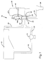
- FIG. 1 there is shown a schematic view of a filter system 10 for use with a source of fluid, such as a swimming pool 12.
- a drain discharge of the swimming pool 12 is connected to an input of a pump 14 through a suction line 16.
- An output of the pump 14 is connected to a first port 18 of a diverter valve 20 through a valve inlet line 22.
- second and third ports 24, 26 of the diverter valve 20 are connected to a filter 28.
- a valve outlet line 30 connects a fourth port 32 of the diverter valve 20 to an inlet of the swimming pool 12.
- a drain line 34 connects a fifth port 36 of the diverter valve 20 to a drain 38.
- the filter 28 has a conventional construction and includes an outer housing 40 with first and second flow connections 42, 44.
- the first flow connection 42 is connected to the second port 24 of the diverter valve 20, while the second flow connection 44 is connected to the third port 26 of the diverter valve 20.
- the filter 28 can be of a bed type, wherein water is filtered through a bed of a filter medium such as sand, or of a diatomaceous earth type, wherein water is filtered through a wire mesh having a coating of diatomaceous earth deposited on it.
- the coating may be formed on the wire mesh by making a slurry of water and diatomaceous earth and circulating it through the filter 28 such that the water passes through the wire mesh while the diatomaceous earth is retained by the wire mesh and becomes deposited thereon. Both types of filter may be cleaned by flowing water in reverse through the filter 28, which is often referred to as backwashing.
- a housing 46 of the diverter valve 20 The housing 46 includes a valve body 48 with the first through fifth ports 18, 24, 26, 32, 36 extending therefrom.
- the valve body 48 is integrally molded from a rigid plastic, such as polyvinyl chloride (PVC) plastic.
- PVC polyvinyl chloride
- the valve body 48 is cylindrical and has threaded top and bottom ends 50, 52.
- the top end 50 includes a circular top edge 54 with a pair of opposing top notches 56 formed therein.
- the bottom end 52 similarly includes a circular a bottom edge with a pair of opposing bottom notches formed therein.
- Each of the first through fifth ports 18, 24, 26, 32, 36 is cylindrical and opens into the valve body 48 through a circular opening 58 formed in the valve body 48.
- the first and fourth ports 18, 32 are located on a front or first side 60 of the valve body 48, while the second and third ports 24, 26 are located on an opposite, rear or second side 62 of the valve body 48.
- the first and second ports 18, 24 are located toward the bottom end 52 of the valve body 48 and are aligned with each other.
- the third and fourth ports 26, 32 are located toward the top end 50 of the valve body 48 and are aligned with each other.
- the fifth port 36 is disposed at a substantially right angle to the first through fourth ports 18, 24, 26, 32, and is disposed between the first and second ports 18, 24 and the bottom end 52 of the valve body 48.
- a top cap assembly is adapted to be secured to the top end 50 of the valve body 48.
- the top cap assembly includes a top insert 66 and one of a pair of retainer caps 68.
- the top insert 66 is integrally molded from a rigid plastic such as acrylonitrile-butadiene-styrene (ABS) plastic.
- the top insert 66 includes a generally circular member 70 having a center opening 72 formed therein.
- An annular flange 74 extends downwardly from a bottom surface of the circular member 70 and is spaced inward from a circumferential edge 76 of the circular member 70.
- An O-ring 78 is provided for disposal around the annular flange 74.
- a pair of opposing tabs 80 extend downwardly from the circumferential edge 76.
- First and second stop blocks 82, 84 extend upwardly from a top surface of the circular member 70.
- the first and second stop blocks 82, 84 are disposed toward the center opening 72 and are orientated at a generally right angle to each other.
- a "BACKWASH" label may be marked on the circular member 70, adjacent to the first stop block 82, while a “FILTER” label may be marked on the circular member 70, adjacent to the second stop block 84.
- the top insert 66 is adapted to be disposed over the top end 50 of the valve body 48 such that the annular flange 74 and the O-ring 78 extend into the top end 50 and the tabs 80 are received in the top notches 56. With the top insert 66 so disposed, the O-ring 78 is compressed between the annular flange 74 and an interior surface 86 of the valve body 48, thereby forming a seal therebetween.
- the retainer cap 68 is integrally molded from a rigid plastic, such as ABS plastic.
- the retainer cap 68 is generally cylindrical and includes a side wall 88 having an interior surface with threads 90 formed therein.
- a plurality of spaced-apart ridges 92 are disposed around the circumference of the side wall 88 and are vertically extending.
- the retainer cap 68 is adapted to be threaded onto the top end 50 of the valve body 48, over the top insert 66, so as to secure the top insert 66 to the valve body 48.
- the ridges 92 help an operator grip the retainer cap 68 when installing or removing the retainer cap 68.
- a bottom cap assembly is adapted to be secured to the bottom end 52 of the valve body 48.
- the bottom cap assembly includes a bottom insert 96 and the other one of the retainer caps 68.
- the bottom insert 96 is integrally molded from a rigid plastic, such as ABS plastic.
- the bottom insert 96 includes an annular member 98 disposed around a hub 100.
- the hub 100 defines a hollow 102 having an upwardly-directed opening.
- An annular flange 104 extends upwardly from an upper surface of the annular member 98.
- the annular flange 104 is disposed around the hub 100 and is spaced inward from a circumferential edge 106 of the annular member 98.
- An O-ring 108 is provided for disposal around the annular flange 104.
- a pair of opposing tabs 110 extend upwardly from the circumferential edge 106.
- the bottom insert 96 is adapted to be disposed over the bottom end 52 of the valve body 48 such that the annular flange 104 and the O-ring 108 extend into the bottom end 52 and the tabs 110 are received in the bottom notches. With the bottom insert 96 so disposed, the O-ring 108 is compressed between the annular flange 104 and the interior surface 86 of the valve body 48, thereby forming a seal therebetween.
- the retainer cap 68 is adapted to be threaded onto the bottom end 52 of the valve body 48, over the bottom insert 96, so as to secure the bottom insert 96 to the valve body 48.
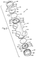
- FIG. 3 there is shown an exploded view of a control assembly comprised of an internal valve assembly 114 and a handle 198.
- the internal valve assembly 114 is for disposal inside the housing 46.
- the internal valve assembly 114 includes a blocking gate 116, a diverter gate 118, and a stop gate or waste seal 120.
- the blocking gate 116 is integrally molded from a rigid plastic, such as ABS plastic.
- the blocking gate 116 includes a generally cylindrical body 122 and a blocking projection 124.
- the body 122 is hollow and has opposing open ends 126 that are generally concave.
- Cylindrical mounts 128 are centrally joined to the body 122 on opposing top and bottom portions thereof.
- the mounts 128 are aligned with each other and are oriented perpendicular to the body 122.
- Each of the mounts 128 defines an opening 130.
- a plurality of spaced-apart ridges 132 extend into each of the openings 130 around the circumferences thereof.
- the blocking projection 124 includes a base (not shown) joined to a generally semi-spherical head 134 (shown best in Figs. 4, 5).
- the base is joined to a side portion of the body 122 and spaces the head 134 from the body 122.
- the head 134 has a face 136 bounded by a circumferential edge 138.
- the face 136 is convex in a lateral direction.
- a pair of ears 140 respectively extend from opposing portions of the circumferential edge 138 to the ends 126 of the body 122.
- the diverter gate 118 is integrally molded from a rigid plastic, such as ABS plastic.
- the diverter gate 118 includes a generally cylindrical body 142.
- the body 142 is hollow and has opposing open ends 144 that are generally concave.
- Cylindrical mounts 146 are centrally joined to the body 142 on opposing top and bottom portions thereof.
- the mounts 146 are aligned with each other and are oriented perpendicular to the body 142.
- Each of the mounts 146 defines a generally circular opening 148.
- a plurality of spaced-apart ridges 150 extend into each of the openings 148 around the circumferences thereof.
- Top and bottom deflector plates 152, 154 are joined to the body 142 and extend in opposing directions therefrom.
- the top deflector plate 152 is joined to a side portion of the body 142, toward the top thereof, while the bottom deflector plate 154 is joined to an opposing side portion of the body 142, toward the bottom thereof.
- the top and bottom deflector plates 152, 154 are each generally semi-circular and respectively have arcuate outer edges 156, 158.
- the waste seal 120 is integrally molded from a rigid plastic, such as ABS plastic.
- the waste seal 120 includes a head 160 joined to a cylindrical base 162.
- a cylindrical cavity (not shown) extends through the base 162 and terminates inside the head 160.
- a furrow (not shown) adjoins the cavity and extends radially outward therefrom.
- the head 160 is generally disk-shaped and is convex in a lateral direction.
- An annular groove 164 is formed in the head for receiving an O-ring 166. The groove 164 is spaced inward from a circumferential edge 168 of the head 160.
- a waste shaft 170 is provided for connection to the waste seal 120.
- the waste shaft 170 is preferably composed of rigid plastic and includes a generally cylindrical base 172 joined to a main body 174.
- a cylindrical mount 176 extends from the main body 174 at a substantially right angle.
- An annular flange 178 is joined between the base 172 and the main body 174.
- the base 172 has a plurality of notches 180 disposed around its perimeter, while a plurality of longitudinal grooves 182 are equally spaced around the perimeter of the main body 174.
- a locking ridge 184 extends along the length of the mount 176.
- a body bore (not shown) extends through the main body 174, while a base bore 186 extends through the base 172.
- the base bore 186 may be threaded.
- a cylindrical hollow 188 is formed in the mount 176.
- a central shaft 190 is provided for connecting the blocking gate 116 to the diverter gate 118.
- the central shaft 190 is preferably composed of rigid plastic and has a generally cylindrical shape.
- a plurality of grooves 192 are formed in the central shaft 190.
- the grooves 192 are equally spaced around the perimeter of the central shaft 190 and extend the length of the central shaft 190.
- a bore 194 extends through the central shaft 190.
- An end shaft 196 is provided for connecting the blocking gate 116 to a handle 198.
- the end shaft 196 is preferably composed of rigid plastic and includes a gate portion 200 and a mounting portion 202.
- An annular flange 206 is joined between the gate portion 200 and the mounting portion 202.
- a plurality of longitudinal grooves 208 are equally spaced around the perimeter of the mounting portion 202, while a plurality of notches 210 are equally spaced around the perimeter of the gate portion 200.
- a lower bore 212 extends through the gate portion 200, while an upper bore (not shown) extends through the mounting portion 202. The upper bore may be threaded.
- the handle 198 is integrally molded from a rigid plastic, such as ABS plastic.
- the handle 198 is generally rectangular, with a slight bend being formed in the handle, toward an arcuate inner end 214 thereof.
- a rectangular protuberance or pointer 216 extends away from the inner end 214.
- a generally circular bottom cavity 218 and a circular top hole (not shown) are formed in the handle 198, toward the inner end 214.
- the bottom cavity 218 extends through a bottom surface of the handle 198, while the top hole extends through a top surface of the handle 198.
- a plurality of spaced-apart ridges 222 extend into the bottom cavity 218 around the circumference of the bottom cavity 218.
- the top hole extends into the bottom cavity 218 and may be threaded.
- Fig. 4 there is shown a front view of the diverter valve 20, fully assembled. A portion of the diverter valve 20 is cut-away to better show the interior thereof.
- the bottom insert 96 (shown in Fig. 2) is disposed over the bottom end 52 of the valve body 48 in the manner described above.
- One of the retainer caps 68 is threaded onto the bottom end 52 of the valve body 48, over the bottom insert 96, thereby securing the bottom insert 96 to the valve body 48 and forming the seal therebetween.
- the base 172 of the waste shaft 170 is rotatably disposed in the hollow 102 of the bottom insert 96 such that the annular flange 178 abuts the hub 100.
- the mount 176 of the waste shaft 170 is disposed in the cavity of the waste seal 120 such that the locking ridge 184 is received in the furrow, thereby securing the waste seal 120 from rotational movement around the mount 176.
- the main body 174 of the waste shaft 170 is disposed inside the opening 148 in a bottom one of the mounts 146 of the diverter gate 118 such that the ridges 150 of the mount 146 extend into the grooves 182 of the main body 174, thereby securing the main body 174 from rotational movement inside the opening 148.
- the central shaft 190 connects the diverter gate 118 to the blocking gate 116.
- a bottom end of the central shaft 190 is disposed inside the opening 148 in a top one of the mounts 146 of the diverter gate 118 such that the ridges 150 of the mount 146 extend into the grooves 192 of the central shaft 190, thereby securing the bottom end of the central shaft 190 from rotational movement inside the opening 148.
- a top end of the central shaft 190 is disposed inside the opening 130 in a bottom one of the mounts 128 of the blocking gate 116 such that the ridges 132 of the mount 128 extend into the grooves 192 of the central shaft 190, thereby securing the top end of the central shaft 190 from rotational movement inside the opening 130.
- the top insert 66 is disposed over the top end 50 of the valve body 48 in the manner described above.
- the other one of the retainer caps 68 is threaded onto the top end 50 of the valve body 48, over the top insert 66, thereby securing the top insert 66 to the valve body 48 and forming the seal therebetween.
- the gate portion 200 of the end shaft 196 is disposed inside the opening 130 in a top one of the mounts 128 of the blocking gate 116 such that the ridges 132 of the mount 128 extend into the notches 210 of the gate portion 200, thereby securing the gate portion 200 of the end shaft 196 from rotational movement inside the opening 130.
- the mounting portion 202 of the end shaft 196 extends through the center opening 72 in the top insert 66.
- the handle 198 is disposed over the mounting portion 202 of the end shaft 196 such that the pointer 216 of the handle 198 is located between the first and second stop blocks 82, 84.
- the mounting portion 202 of the end shaft 196 is disposed in the bottom cavity 218 of the handle 198 such that the ridges 222 of the handle 198 extend into the grooves 208 of the end shaft 196, thereby securing the mounting portion 202 of the end shaft 196 from rotational movement inside the bottom cavity 218.
- a fastening bolt 230 (shown in Figs. 4, 5) may be threaded through the top hole in the handle 198 and into the upper bore of the end shaft 196 so as to secure the handle 198 to the internal valve assembly 114.
- the internal valve assembly 114 is rotatably disposed inside the valve body 48.
- the blocking gate 116 is disposed between the third and fourth ports 26, 32 of the valve body 48, while the diverter gate 118 is disposed between the first and second ports 18, 24 of the housing 46.
- the waste seal 120 is vertically aligned with the fifth port 36.
- the internal valve assembly 114 may be rotated between a filter position (shown in Fig. 4) and a backwash position (shown in Fig. 5) by moving handle 198 such that the pointer 216 moves between the first and second stop blocks 82, 84.
- the body 122 of the blocking gate 116 extends lengthwise between the third and fourth ports 26, 32
- the body 142 of the diverter gate 118 extends lengthwise between the first and second ports 18, 24.
- the head 160 of the waste seal 120 is disposed over the fifth port 36.
- the blocking gate 116 functions as a conduit for conducting fluid between the third and fourth ports 26, 32 in a linear manner.
- the diverter gate 118 functions as a conduit for conducting fluid between the first and second ports 18, 24 in a linear manner.
- the O-ring 166 on the head 160 of the waste seal 120 forms a seal with the interior surface 86 of the valve body 48 around the fifth port 36, thereby sealing off the fifth port 36 from the interior of the valve body 48.
- Fig. 5 there is shown a cut-away side view of the diverter valve 20 with the internal valve assembly 114 in the backwash position.
- the body 122 of the blocking gate 116 extends transverse to the direction between the third and fourth ports 26, 32
- the body 142 of the diverter gate 118 extends transverse to the direction between the first and second ports 18, 24.
- the waste seal 120 is spaced from the fifth port 36 so as to permit the fifth port 36 to communicate with the interior of the valve body 48.
- the blocking projection 124 of the blocking gate 116 is disposed over the fourth port 32 such that the face 136 of the blocking projection 124 adjoins the interior surface 86 of the valve body 48 around the fourth port 32, thereby closing off the fourth port 32 from the interior of the valve body 48.
- the outer edge 158 of the bottom deflector plate 154 adjoins the interior surface 86 of the valve body 48 on the first side 60 thereof.
- the bottom deflector plate 154 is located below the opening 58 of the first port 18 and above the opening 58 of the fifth port 36.
- the bottom deflector plate 154 cooperates with the body 142 of the diverter gate 118 to guide fluid entering the valve body 48 through the first port 18 upward, along the first side 60 of the valve body 48. Once above the diverter gate 118, the fluid from the first port 18 crosses over to the second side 62 of the valve body 48 and exits the valve body 48 through the third port 26.
- the outer edge 152 of the top deflector plate 152 adjoins the interior surface 86 of the valve body 48 on the second side 62 thereof.
- the top deflector plate 152 is located above the opening 58 of the second port 24 and thereby prevents fluid from the first port 18 from travelling downward, into the second port 24 or the fifth port 36.
- the blocking projection 124 of the blocking gate 116 prevents fluid from the first port 18 from exiting the valve body 48 through the fourth port 32.
- the diverter gate 118 and the blocking gate 116 cooperate to define a passage through the valve body 48 that connects the first port 18 to the third port 26 when the internal valve assembly 114 is in the backwash position.
- the top deflector plate 152 also cooperates with the body 142 of the diverter gate 118 to guide fluid entering the valve body 48 through the second port 24 downward, along the second side 62 of the valve body 48. Below the diverter gate 118, the fluid from the second port 24 exits the valve body 48 through the fifth port 36.
- the bottom deflector plate 154 prevents fluid from the second port 24 from traveling upward along the first side 60 of the valve body 48 to the first port 18.
- the diverter gate 118 helps define a passage through the valve body 48 that connects the second port 24 to the fifth port 36 when the internal valve assembly 114 is in the backwash position.
- the internal valve assembly 114 is placed in the filter position by rotating the handle 198 such that the pointer 216 abuts the second stop block 84.
- the pump 14 draws water from the swimming pool 12 and pumps it to the diverter valve 20 through the valve inlet line 22.
- the water enters the diverter valve 20 through the first port 18, travels axially through the diverter gate 118, and exits the diverter valve 20 through the second port 24.
- the water enters the filter 28 through the first flow connection 42 and passes through the filter bed or coated wire mesh in a first direction, which causes impurities in the water to be removed and retained by the filter bed or coated wire mesh.
- the filtered water then exits the filter 28 through the second flow connection 44 and re-enters the diverter valve 20 through the third port 26.
- the filtered water travels axially through the blocking gate 116 and exits the diverter valve 20 through the fourth port 32.
- the filtered water then travels back to the swimming pool 12 through the valve outlet line 30.
- the internal valve assembly 114 is placed in the backwash position by rotating the handle 198 such that the pointer 216 abuts the first stop block 82.
- the pump 14 draws water from the swimming pool 12 and pumps it to the diverter valve 20 through the valve inlet line 22.
- the water enters the diverter valve 20 through the first port 18, travels upward through the diverter valve 20, and exits the diverter valve 20 through the third port 26.
- the water enters the filter 28 through the second flow connection 44 and passes through the filter bed or coated wire mesh in an opposite, second direction, which flushes the impurities out of the filter bed or coated wire mesh.
- the water also flushes the diatomaceous earth off the wire mesh.
- the impurities (and, if applicable, the diatomaceous earth) is mixed with the water to form a waste mixture and is carried out of the filter 28.
- the waste mixture exits the filter 28 through the first flow connection 42 and re-enters the diverter valve 20 through the second port 24.
- the waste mixture travels downward through the valve body 48 and exits the diverter valve 20 through the fifth port 36.
- the waste mixture then travels to the drain 38 through the drain line 34.
- the diverter valve 20 provides numerous benefits over prior art diverter valves.
- the construction of the diverter valve 20 permits the diverter valve 20 to be re-configured for a particular application. For example, if the diverter valve 20 is to be used in another filter system where the first and second flow connections 42, 44 of the filter 28 are reversed in position, the valve body 48 can be turned upside down and the top and bottom cap assemblies swapped.
- the base 172 of the waste shaft 170 extends through the center opening 72 in the top insert 66 and into the bottom cavity 218 of the handle 198, while the mounting portion 202 of the end shaft 196 is rotatably disposed in the hollow 102 of the bottom insert 96.
- the ridges 222 of the handle 198 extend into the notches 180 of the base 172 so as to secure the waste shaft 170 from rotational movement inside the bottom cavity 218.
- the fastening bolt 230 may be threaded through the top hole in the handle 198 and into the base bore 186 of the waste shaft 170 so as to secure the handle 198 to the internal valve assembly 114.
- the construction of the diverter valve 20 also permits the diverter valve 20 to be manufactured using less labor than other prior art diverter valves.
- the components of the diverter valve 20 may be machine molded and can be quickly assembled together using, at most, only one fastening element (the fastening bolt 230).
- the diverter valve 20 does not introduce a substantial pressure drop into the filter system 10 when the diverter valve 20 is in the filter position because the water flows linearly through the diverter gate 118 and the blocking gate 116.
Landscapes
- Engineering & Computer Science (AREA)
- General Engineering & Computer Science (AREA)
- Mechanical Engineering (AREA)
- Multiple-Way Valves (AREA)
- Valve Housings (AREA)
- Sliding Valves (AREA)
Applications Claiming Priority (2)
| Application Number | Priority Date | Filing Date | Title |
|---|---|---|---|
| US08/950,813 US5937903A (en) | 1997-10-15 | 1997-10-15 | High performance diverter valve |
| US950813 | 1997-10-15 |
Publications (3)
| Publication Number | Publication Date |
|---|---|
| EP0909911A2 true EP0909911A2 (fr) | 1999-04-21 |
| EP0909911A3 EP0909911A3 (fr) | 2000-09-20 |
| EP0909911B1 EP0909911B1 (fr) | 2004-07-28 |
Family
ID=25490874
Family Applications (1)
| Application Number | Title | Priority Date | Filing Date |
|---|---|---|---|
| EP19980303924 Expired - Lifetime EP0909911B1 (fr) | 1997-10-15 | 1998-05-15 | Vanne de dérivation |
Country Status (6)
| Country | Link |
|---|---|
| US (1) | US5937903A (fr) |
| EP (1) | EP0909911B1 (fr) |
| AU (1) | AU739334B2 (fr) |
| DE (1) | DE69825231T2 (fr) |
| ES (1) | ES2226068T3 (fr) |
| GB (1) | GB9809206D0 (fr) |
Cited By (5)
| Publication number | Priority date | Publication date | Assignee | Title |
|---|---|---|---|---|
| US20100147086A1 (en) * | 2008-12-11 | 2010-06-17 | Spark Holland B.V. | Method and apparatus for injecting a liquid sample in an HPLC analyzing device, and valve assembly for use therein |
| US8690855B2 (en) * | 2010-12-22 | 2014-04-08 | Medtronic Minimed, Inc. | Fluid reservoir seating procedure for a fluid infusion device |
| US9017307B2 (en) | 2010-12-22 | 2015-04-28 | Medtronic Minimed, Inc. | Occlusion detection for a fluid infusion device |
| US9770553B2 (en) | 2010-12-22 | 2017-09-26 | Medtronic Minimed, Inc. | Monitoring the operating health of a force sensor in a fluid infusion device |
| WO2018115713A1 (fr) | 2016-12-20 | 2018-06-28 | Zodiac Pool Care Europe | Vanne compacte multivoie de raccordement entre deux circuits de circulation de fluide |
Families Citing this family (20)
| Publication number | Priority date | Publication date | Assignee | Title |
|---|---|---|---|---|
| US6568428B2 (en) * | 1998-07-23 | 2003-05-27 | Laars, Inc. | Backwash valve |
| CN1148521C (zh) * | 2000-04-03 | 2004-05-05 | 王斌 | 旋板式五通换向阀 |
| KR101272966B1 (ko) | 2003-10-17 | 2013-06-10 | 액세스 비지니스 그룹 인터내셔날 엘엘씨 | 변환기 밸브 조립체 및 유체 유동을 변환하는 방법 |
| US7255129B2 (en) | 2005-02-01 | 2007-08-14 | Pentair Water Pool And Spa, Inc. | Valve with elbow joint diverter |
| US7736500B2 (en) * | 2005-12-22 | 2010-06-15 | Awtp, Llc | Bypass valve with blending feature |
| US7849877B2 (en) | 2007-03-01 | 2010-12-14 | Zodiac Pool Systems, Inc. | Diverter valve |
| CN102209815B (zh) * | 2008-11-10 | 2014-10-29 | 捷通国际有限公司 | 水龙头阀门系统 |
| US8375970B2 (en) * | 2008-11-10 | 2013-02-19 | Access Business Group International Llc | Valve system |
| US9816627B2 (en) * | 2011-02-15 | 2017-11-14 | Origin Medical Devices Inc. | Variable orifice rotary valves for controlling gas flow |
| US9707499B2 (en) | 2013-03-15 | 2017-07-18 | Hayward Industries, Inc. | Vertical slide backwash valve |
| US9500299B2 (en) * | 2013-07-25 | 2016-11-22 | Schaeffler Technologies AG & Co. KG | Thermal management valve module with isolated flow chambers |
| US10883619B2 (en) * | 2017-06-27 | 2021-01-05 | Hayward Industries, Inc. | Multi-position valve |
| US10240682B2 (en) * | 2017-07-24 | 2019-03-26 | Schaeffler Technologies AG & Co. KG | Over-molded splines for rotary valves |
| US11384591B2 (en) * | 2018-04-18 | 2022-07-12 | Tadpole Products, Llc | System for electronic doorframe |
| US10855064B2 (en) * | 2018-04-18 | 2020-12-01 | Tadpole Products, Llc | System for electronic doorframe |
| US10411447B1 (en) * | 2018-04-18 | 2019-09-10 | Steed Hammond Paul, Inc. | System for electronic doorframe |
| WO2020264298A1 (fr) | 2019-06-28 | 2020-12-30 | Cameron International Corporation | Soupape d'étranglement réglable résistante à l'érosion |
| KR102750675B1 (ko) | 2020-03-24 | 2025-01-06 | 현대자동차주식회사 | 워셔액 분배장치 및 분배방법 |
| US11331616B2 (en) * | 2020-09-25 | 2022-05-17 | Mark Henderson | Pool filter assembly |
| US11796073B2 (en) * | 2021-02-03 | 2023-10-24 | Robertshaw Controls Company | Six port valve |
Citations (2)
| Publication number | Priority date | Publication date | Assignee | Title |
|---|---|---|---|---|
| US3712268A (en) | 1971-06-02 | 1973-01-23 | J Reed | Portable bacteriological incubator |
| US4714551A (en) | 1984-06-26 | 1987-12-22 | Bruno Bachhofer | 5/2-Way commutating valve, particularly for reverse-flush filters |
Family Cites Families (35)
| Publication number | Priority date | Publication date | Assignee | Title |
|---|---|---|---|---|
| US413671A (en) * | 1889-10-29 | jewell | ||
| US860672A (en) * | 1905-05-25 | 1907-07-23 | James B Ladd | Reversing-valve. |
| GB324239A (en) * | 1929-01-31 | 1930-01-23 | Edward Alexander Stanley Swins | A multiple-way or interchange plug cock |
| GB481685A (en) * | 1936-12-01 | 1938-03-16 | Walter Riggs | Improvements relating to plug valves |
| US2137406A (en) * | 1936-12-08 | 1938-11-22 | Puritan Engineering Corp | Water softener valve |
| US2662549A (en) * | 1949-05-02 | 1953-12-15 | Belco Ind Equipment Division I | Multiport valve |
| US3166499A (en) * | 1960-10-26 | 1965-01-19 | Bruner Corp | Ion exchange water softening system |
| US3195726A (en) * | 1962-06-18 | 1965-07-20 | Saurenman Co Inc | Control valve means for swimming pool filter and backwash operations |
| US3365064A (en) * | 1965-10-14 | 1968-01-23 | Jacuzzi Bros Inc | Swimming pool system and backwash assembly therefor |
| US3471021A (en) * | 1966-02-07 | 1969-10-07 | Swimquip Inc | Valve and liquid flow system |
| US3499467A (en) * | 1967-04-12 | 1970-03-10 | Lunkenheimer Co | Multiple flow-pattern valve |
| DE2019691A1 (de) * | 1970-04-23 | 1972-01-20 | Cillichemie | Filter- und Rueckspuelvorrichtung fuer Schwimmbecken |
| US3721268A (en) * | 1970-12-03 | 1973-03-20 | G Erlich | Multiport valve with rotatable cover |
| US3907688A (en) * | 1971-04-05 | 1975-09-23 | Carborundum Co | Valve for a filter |
| US3809247A (en) * | 1972-11-09 | 1974-05-07 | Purex Corp Ltd | High throughput filter having multiposition valve |
| US3874413A (en) * | 1973-04-09 | 1975-04-01 | Vals Construction | Multiported valve |
| JPS5057971A (fr) * | 1973-09-26 | 1975-05-20 | ||
| JPS51136571A (en) * | 1975-05-21 | 1976-11-26 | Nittetsu Kakoki Kk | Solid-fluid contact apparatus |
| CH583393A5 (en) * | 1975-08-22 | 1976-12-31 | Keusch Paul | Two position switch over valve - has two inlets and two outlets to reverse flow to clean filter |
| US4312377A (en) * | 1979-08-29 | 1982-01-26 | Teledyne Adams, A Division Of Teledyne Isotopes, Inc. | Tubular valve device and method of assembly |
| US4355659A (en) * | 1981-01-08 | 1982-10-26 | The Hilliard Corp. | Rotary plug valve |
| US4466457A (en) * | 1982-02-18 | 1984-08-21 | Brane Earl P | Bypass and hard water mix valve |
| US4469131A (en) * | 1982-07-12 | 1984-09-04 | Traylor Paul L | Spool valve |
| US4555334A (en) * | 1983-03-21 | 1985-11-26 | Performance Pool Products, Ltd. | Method and apparatus for cleaning a purgible swimming pool strainer |
| US4564451A (en) * | 1983-03-21 | 1986-01-14 | Performance Pool Products, Ltd. | Apparatus for cleaning a swimming pool strainer |
| US4553566A (en) * | 1984-04-06 | 1985-11-19 | The United States Of America As Represented By The United States Department Of Energy | Rotary multiposition valve |
| US4545905A (en) * | 1984-05-30 | 1985-10-08 | Poe James T | Filter backwash water saver and water filter to clean swimming pool filter |
| US4678564A (en) * | 1985-11-15 | 1987-07-07 | Fairchild Filter Corporation | Cast filter and automatic self-cleaning backflush control system therefor |
| US4669503A (en) * | 1986-04-21 | 1987-06-02 | Bristol Corporation | Three-way valve |
| DE3889185D1 (de) * | 1987-07-17 | 1994-05-26 | Kurt Michael Desch | Zentralsteuerventil für eine Wasseraufbereitungsanlage. |
| US4909933A (en) * | 1988-09-15 | 1990-03-20 | The United States Of America As Represented By The Administrator Of The National Aeronautics And Space Administration | Apparatus for mixing solutions in low gravity environments |
| DE8907211U1 (de) * | 1989-06-13 | 1989-07-27 | Hydac Filtertechnik GmbH, 6603 Sulzbach | Umschaltarmatur |
| US5152321A (en) * | 1991-10-07 | 1992-10-06 | Ecowater Systems, Inc. | Bypass valve |
| US5366021A (en) * | 1993-04-23 | 1994-11-22 | Aquapad Usa, Inc. | Fire fighting equipment for use in association with homes equipped with swimming pools |
| US5505844A (en) * | 1994-06-23 | 1996-04-09 | Porter; Mark A. | Swimming pool backwash filter |
-
1997
- 1997-10-15 US US08/950,813 patent/US5937903A/en not_active Expired - Lifetime
-
1998
- 1998-04-28 AU AU63670/98A patent/AU739334B2/en not_active Ceased
- 1998-04-29 GB GB9809206A patent/GB9809206D0/en active Pending
- 1998-05-15 EP EP19980303924 patent/EP0909911B1/fr not_active Expired - Lifetime
- 1998-05-15 DE DE1998625231 patent/DE69825231T2/de not_active Expired - Fee Related
- 1998-05-15 ES ES98303924T patent/ES2226068T3/es not_active Expired - Lifetime
Patent Citations (2)
| Publication number | Priority date | Publication date | Assignee | Title |
|---|---|---|---|---|
| US3712268A (en) | 1971-06-02 | 1973-01-23 | J Reed | Portable bacteriological incubator |
| US4714551A (en) | 1984-06-26 | 1987-12-22 | Bruno Bachhofer | 5/2-Way commutating valve, particularly for reverse-flush filters |
Cited By (12)
| Publication number | Priority date | Publication date | Assignee | Title |
|---|---|---|---|---|
| US20100147086A1 (en) * | 2008-12-11 | 2010-06-17 | Spark Holland B.V. | Method and apparatus for injecting a liquid sample in an HPLC analyzing device, and valve assembly for use therein |
| US8322197B2 (en) * | 2008-12-11 | 2012-12-04 | Spark Hollands B.V. | Method and apparatus for injecting a liquid sample in an HPLC analyzing device, and valve assembly for use therein |
| US8690855B2 (en) * | 2010-12-22 | 2014-04-08 | Medtronic Minimed, Inc. | Fluid reservoir seating procedure for a fluid infusion device |
| US9017307B2 (en) | 2010-12-22 | 2015-04-28 | Medtronic Minimed, Inc. | Occlusion detection for a fluid infusion device |
| US9033951B2 (en) | 2010-12-22 | 2015-05-19 | Medtronic Minimed, Inc. | Occlusion detection for a fluid infusion device |
| US9050406B2 (en) | 2010-12-22 | 2015-06-09 | Medtronic Minimed, Inc. | Occlusion detection for a fluid infusion device |
| US9555190B2 (en) | 2010-12-22 | 2017-01-31 | Medtronic Minimed, Inc. | Fluid reservoir seating procedure for a fluid infusion device |
| US9770553B2 (en) | 2010-12-22 | 2017-09-26 | Medtronic Minimed, Inc. | Monitoring the operating health of a force sensor in a fluid infusion device |
| US9895490B2 (en) | 2010-12-22 | 2018-02-20 | Medtronic Minimed, Inc. | Occlusion detection for a fluid infusion device |
| US10071200B2 (en) | 2010-12-22 | 2018-09-11 | Medtronic Minimed, Inc. | Fluid reservoir seating procedure for a fluid infusion device |
| US10478554B2 (en) | 2010-12-22 | 2019-11-19 | Medtronic Minimed, Inc. | Monitoring the operating health of a force sensor in a fluid infusion device |
| WO2018115713A1 (fr) | 2016-12-20 | 2018-06-28 | Zodiac Pool Care Europe | Vanne compacte multivoie de raccordement entre deux circuits de circulation de fluide |
Also Published As
| Publication number | Publication date |
|---|---|
| AU6367098A (en) | 1999-05-06 |
| AU739334B2 (en) | 2001-10-11 |
| ES2226068T3 (es) | 2005-03-16 |
| US5937903A (en) | 1999-08-17 |
| DE69825231T2 (de) | 2005-08-04 |
| EP0909911A3 (fr) | 2000-09-20 |
| EP0909911B1 (fr) | 2004-07-28 |
| DE69825231D1 (de) | 2004-09-02 |
| GB9809206D0 (en) | 1998-07-01 |
Similar Documents
| Publication | Publication Date | Title |
|---|---|---|
| US5937903A (en) | High performance diverter valve | |
| US11988297B2 (en) | Multi-position valve | |
| US7000782B2 (en) | Backwash flushing filter | |
| KR0156082B1 (ko) | 디버터 및 이를 구비한 정수기 | |
| EP0207233B1 (fr) | Robinet d'arrêt contenant une passoire | |
| US3707233A (en) | Filter tank and mounting adaptor for multiport valves | |
| US6165355A (en) | Fluid filter having a three way valve construction | |
| EP1504801A1 (fr) | Filtre a combustible avec deviateur de flux | |
| US20150202552A1 (en) | Liquid filter drain with integral air vent | |
| US3911956A (en) | Multiport valve | |
| JPH04203681A (ja) | ろ過器用の切換え弁装置 | |
| US4806258A (en) | Straining and stop valve | |
| JP3320185B2 (ja) | 液体濾過用フィルタ装置 | |
| JPH06137442A (ja) | 浄水器の切換え弁装置 | |
| JPS629072A (ja) | ストレ−ナ付ボ−ルバルブ | |
| CA2547882C (fr) | Filtre a chasse et a lavage a contre-courant | |
| CN220328138U (zh) | 一种球阀式前置过滤器 | |
| JPH09303614A (ja) | 弁部材内蔵型ストレ―ナ | |
| CN223434787U (zh) | 不间断供水过滤阀 | |
| CN216223277U (zh) | 龙头净水器 | |
| JPS637737Y2 (fr) | ||
| GB2174920A (en) | Irrigation water filter | |
| CN222534224U (zh) | 一种滤芯接座及滤芯组件 | |
| JPH0248005Y2 (fr) | ||
| JP4077564B2 (ja) | 浄水器 |
Legal Events
| Date | Code | Title | Description |
|---|---|---|---|
| PUAI | Public reference made under article 153(3) epc to a published international application that has entered the european phase |
Free format text: ORIGINAL CODE: 0009012 |
|
| AK | Designated contracting states |
Kind code of ref document: A2 Designated state(s): BE DE ES FR GB IT NL |
|
| AX | Request for extension of the european patent |
Free format text: AL;LT;LV;MK;RO;SI |
|
| PUAL | Search report despatched |
Free format text: ORIGINAL CODE: 0009013 |
|
| AK | Designated contracting states |
Kind code of ref document: A3 Designated state(s): AT BE CH CY DE DK ES FI FR GB GR IE IT LI LU MC NL PT SE |
|
| AX | Request for extension of the european patent |
Free format text: AL;LT;LV;MK;RO;SI |
|
| RIC1 | Information provided on ipc code assigned before grant |
Free format text: 7F 16K 11/085 A, 7E 04H 4/12 B |
|
| 17P | Request for examination filed |
Effective date: 20010103 |
|
| AKX | Designation fees paid |
Free format text: BE DE ES FR GB IT NL |
|
| 17Q | First examination report despatched |
Effective date: 20021120 |
|
| RAP1 | Party data changed (applicant data changed or rights of an application transferred) |
Owner name: PENTAIR POOL PRODUCTS, INC. |
|
| GRAP | Despatch of communication of intention to grant a patent |
Free format text: ORIGINAL CODE: EPIDOSNIGR1 |
|
| GRAS | Grant fee paid |
Free format text: ORIGINAL CODE: EPIDOSNIGR3 |
|
| GRAA | (expected) grant |
Free format text: ORIGINAL CODE: 0009210 |
|
| AK | Designated contracting states |
Kind code of ref document: B1 Designated state(s): BE DE ES FR GB IT NL |
|
| PG25 | Lapsed in a contracting state [announced via postgrant information from national office to epo] |
Ref country code: NL Free format text: LAPSE BECAUSE OF FAILURE TO SUBMIT A TRANSLATION OF THE DESCRIPTION OR TO PAY THE FEE WITHIN THE PRESCRIBED TIME-LIMIT Effective date: 20040728 Ref country code: IT Free format text: LAPSE BECAUSE OF FAILURE TO SUBMIT A TRANSLATION OF THE DESCRIPTION OR TO PAY THE FEE WITHIN THE PRESCRIBED TIME-LIMIT;WARNING: LAPSES OF ITALIAN PATENTS WITH EFFECTIVE DATE BEFORE 2007 MAY HAVE OCCURRED AT ANY TIME BEFORE 2007. THE CORRECT EFFECTIVE DATE MAY BE DIFFERENT FROM THE ONE RECORDED. Effective date: 20040728 Ref country code: BE Free format text: LAPSE BECAUSE OF FAILURE TO SUBMIT A TRANSLATION OF THE DESCRIPTION OR TO PAY THE FEE WITHIN THE PRESCRIBED TIME-LIMIT Effective date: 20040728 |
|
| REG | Reference to a national code |
Ref country code: GB Ref legal event code: FG4D |
|
| REF | Corresponds to: |
Ref document number: 69825231 Country of ref document: DE Date of ref document: 20040902 Kind code of ref document: P |
|
| NLV1 | Nl: lapsed or annulled due to failure to fulfill the requirements of art. 29p and 29m of the patents act | ||
| REG | Reference to a national code |
Ref country code: ES Ref legal event code: FG2A Ref document number: 2226068 Country of ref document: ES Kind code of ref document: T3 |
|
| PLBE | No opposition filed within time limit |
Free format text: ORIGINAL CODE: 0009261 |
|
| STAA | Information on the status of an ep patent application or granted ep patent |
Free format text: STATUS: NO OPPOSITION FILED WITHIN TIME LIMIT |
|
| ET | Fr: translation filed | ||
| 26N | No opposition filed |
Effective date: 20050429 |
|
| PGFP | Annual fee paid to national office [announced via postgrant information from national office to epo] |
Ref country code: DE Payment date: 20070702 Year of fee payment: 10 |
|
| PGFP | Annual fee paid to national office [announced via postgrant information from national office to epo] |
Ref country code: GB Payment date: 20070525 Year of fee payment: 10 |
|
| PGFP | Annual fee paid to national office [announced via postgrant information from national office to epo] |
Ref country code: FR Payment date: 20070517 Year of fee payment: 10 |
|
| PGFP | Annual fee paid to national office [announced via postgrant information from national office to epo] |
Ref country code: ES Payment date: 20080526 Year of fee payment: 11 |
|
| GBPC | Gb: european patent ceased through non-payment of renewal fee |
Effective date: 20080515 |
|
| REG | Reference to a national code |
Ref country code: FR Ref legal event code: ST Effective date: 20090119 |
|
| PG25 | Lapsed in a contracting state [announced via postgrant information from national office to epo] |
Ref country code: FR Free format text: LAPSE BECAUSE OF NON-PAYMENT OF DUE FEES Effective date: 20080602 Ref country code: DE Free format text: LAPSE BECAUSE OF NON-PAYMENT OF DUE FEES Effective date: 20081202 |
|
| PG25 | Lapsed in a contracting state [announced via postgrant information from national office to epo] |
Ref country code: GB Free format text: LAPSE BECAUSE OF NON-PAYMENT OF DUE FEES Effective date: 20080515 |
|
| REG | Reference to a national code |
Ref country code: ES Ref legal event code: FD2A Effective date: 20090516 |
|
| PG25 | Lapsed in a contracting state [announced via postgrant information from national office to epo] |
Ref country code: ES Free format text: LAPSE BECAUSE OF NON-PAYMENT OF DUE FEES Effective date: 20090516 |