EP0909862A1 - Improved motor driven device for opening a motor vehicle lock - Google Patents
Improved motor driven device for opening a motor vehicle lock Download PDFInfo
- Publication number
- EP0909862A1 EP0909862A1 EP98119265A EP98119265A EP0909862A1 EP 0909862 A1 EP0909862 A1 EP 0909862A1 EP 98119265 A EP98119265 A EP 98119265A EP 98119265 A EP98119265 A EP 98119265A EP 0909862 A1 EP0909862 A1 EP 0909862A1
- Authority
- EP
- European Patent Office
- Prior art keywords
- actuator
- wheel
- lock
- opening
- cut
- Prior art date
- Legal status (The legal status is an assumption and is not a legal conclusion. Google has not performed a legal analysis and makes no representation as to the accuracy of the status listed.)
- Ceased
Links
Images


Classifications
-
- E—FIXED CONSTRUCTIONS
- E05—LOCKS; KEYS; WINDOW OR DOOR FITTINGS; SAFES
- E05B—LOCKS; ACCESSORIES THEREFOR; HANDCUFFS
- E05B81/00—Power-actuated vehicle locks
- E05B81/02—Power-actuated vehicle locks characterised by the type of actuators used
- E05B81/04—Electrical
- E05B81/06—Electrical using rotary motors
-
- E—FIXED CONSTRUCTIONS
- E05—LOCKS; KEYS; WINDOW OR DOOR FITTINGS; SAFES
- E05B—LOCKS; ACCESSORIES THEREFOR; HANDCUFFS
- E05B1/00—Knobs or handles for wings; Knobs, handles, or press buttons for locks or latches on wings
- E05B1/0038—Sliding handles, e.g. push buttons
-
- E—FIXED CONSTRUCTIONS
- E05—LOCKS; KEYS; WINDOW OR DOOR FITTINGS; SAFES
- E05B—LOCKS; ACCESSORIES THEREFOR; HANDCUFFS
- E05B81/00—Power-actuated vehicle locks
- E05B81/12—Power-actuated vehicle locks characterised by the function or purpose of the powered actuators
- E05B81/16—Power-actuated vehicle locks characterised by the function or purpose of the powered actuators operating on locking elements for locking or unlocking action
-
- E—FIXED CONSTRUCTIONS
- E05—LOCKS; KEYS; WINDOW OR DOOR FITTINGS; SAFES
- E05B—LOCKS; ACCESSORIES THEREFOR; HANDCUFFS
- E05B81/00—Power-actuated vehicle locks
- E05B81/24—Power-actuated vehicle locks characterised by constructional features of the actuator or the power transmission
- E05B81/32—Details of the actuator transmission
- E05B81/42—Cams
-
- E—FIXED CONSTRUCTIONS
- E05—LOCKS; KEYS; WINDOW OR DOOR FITTINGS; SAFES
- E05B—LOCKS; ACCESSORIES THEREFOR; HANDCUFFS
- E05B81/00—Power-actuated vehicle locks
- E05B81/54—Electrical circuits
- E05B81/64—Monitoring or sensing, e.g. by using switches or sensors
- E05B81/76—Detection of handle operation; Detection of a user approaching a handle; Electrical switching actions performed by door handles
-
- E—FIXED CONSTRUCTIONS
- E05—LOCKS; KEYS; WINDOW OR DOOR FITTINGS; SAFES
- E05B—LOCKS; ACCESSORIES THEREFOR; HANDCUFFS
- E05B15/00—Other details of locks; Parts for engagement by bolts of fastening devices
- E05B15/0053—Other details of locks; Parts for engagement by bolts of fastening devices means providing a stable, i.e. indexed, position of lock parts
-
- E—FIXED CONSTRUCTIONS
- E05—LOCKS; KEYS; WINDOW OR DOOR FITTINGS; SAFES
- E05B—LOCKS; ACCESSORIES THEREFOR; HANDCUFFS
- E05B83/00—Vehicle locks specially adapted for particular types of wing or vehicle
- E05B83/36—Locks for passenger or like doors
Definitions
- the invention relates to a motorized device improved for opening a vehicle lock automobile.
- the invention relates more particularly to a motorized device for opening a vehicle lock automobile, of the type comprising a control member which can be brought by a user from a rest position to a open position in which it controls the supply of an electric motor which drives a linkage according to a lock opening cycle.
- the electronic control circuit must therefore use limit switches sensibly arranged in the device and include timing means and reversing the direction of the motor supply current electric.
- the object of the invention is therefore to propose a device motorized opening which allows in particular to simplify the maximum electronic control circuit of the vehicle.
- the invention provides a motorized device opening a motor vehicle lock, of the type comprising a control member which can be brought by a user from a rest position to an open position in which it controls the supply of an electric motor which leads to a linkage according to an opening cycle of the lock, the opening device comprising an actuator which is movable between a feeding position, in which the motor is electrically powered, and a cut-off position in which the motor supply is cut off, the actuator being brought from its cut-off position to its position supply by the control unit when the latter is brought by the user from its rest position to its position opening and, at the end of the lock opening cycle, the linkage brings the actuator back to its cut-off position, characterized in that the actuator is carried by the control on which it is movable between a relative position advanced, which it occupies when the actuator and the control are simultaneously in their respective positions of cut off and rest or simultaneously in their position supply and opening, and a relative position moved away that it occupies when the control member is in position the actuator is returned to the position break.
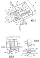
- the device 10 which is illustrated in the figures is intended to ensure the opening of a lock (not shown) which keeps a vehicle leaf in the closed position automobile.
- the device 10 is motorized in that it comprises a electric motor 12 which, when powered, causes the passage of a control linkage 14 of the lock of a state closing in an opening state in which the lock releases the opening which can then be opened.
- the electric motor 12 also controls the return of the linkage 14 to an initial closing state in which the lock is brought into a state in which it is susceptible again to keep the sash in the closed position.
- the user causes the opening of the lock by bringing a control member, here produced in the form of a pusher 16, from a position longitudinal retracted from rest, illustrated for example in Figures 2 and 3, in an advanced longitudinal opening position illustrated for example in Figures 5 and 6.
- the pusher 16 is therefore slidably mounted along a longitudinal axis A1 in a box 18 which is illustrated more particularly in Figure 2 and which is intended to be fixed to a body element of the vehicle in such a way that the pusher 16 is accessible from outside the vehicle.
- the linkage 14 which is arranged longitudinally in front of a front transverse wall 20 of the housing 18, comprises essentially a control wheel 22, a return lever 24 and a connecting rod 26.
- the wheel 22 is rotatably mounted about its axis longitudinal A2, parallel to the sliding axis A1 of the pusher 16, and it is likely to be driven in rotation by the electric motor 12 including the motor shaft, of axis A3 parallel to axis A2, carries a pinion 28 which meshes with a external cylindrical toothed surface 30 of the wheel 22.
- the return lever 24 is pivotally mounted around a axis A4, parallel to axes A2 and A3 of wheel 22 and of the motor 12, in a plane arranged longitudinally behind the wheel 22 but in front of the front transverse wall 20 of the housing 18.
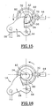
- the lever 24 includes a feeler finger 32 which is intended to cooperate with a cam 34 which is arranged in relief on a rear transverse surface 36 of the wheel 22.
- the cam 34 has a lateral surface 38 which is offset by relative to the axis A2 of rotation of the wheel and the lever 24 is rotated around its axis A4 by means elastic (not shown) so that his finger probing 32 is in abutment, radially with respect to the axis A2, against the lateral surface 38 of the cam 34.
- the probing finger 32 follows the profile of the cam surface 38 which rotates with the wheel 22 and, according to this profile, causes the return lever 24 to rotate about its axis A4.
- Rod 26 is connected by one of its ends 40 rotating around an axis A5, parallel to axes A4 and A2, at lever 24 so that when it pivots about its axis A4, the rod 26 is driven substantially by a movement of translation according to its direction of elongation.
- the other extremity (not shown) of the rod 26 being connected to the lock of opening it, the device 10 is thus capable of controlling the opening of the lock thanks to the linkage 14.
- the motor electric 12 and the wheel 22 are intended to be received in a front housing 42 fixed in front of the housing 18.
- the profile of the cam surface 38 of the cam 34 is such that a opening cycle of the control linkage 14 of the lock, which involves the transition from a closed state to a state opening and - a return to the initial closing state, corresponds to one complete revolution of wheel 22.
- the electric motor 12 is always controlled in the same direction of rotation since, after a full revolution of the wheel 22, the feeler finger 32 finds itself in abutment against a portion of the control surface 38 which corresponds to the state of closing the lock; after going through the entire profile of the surface 38 which causes it to pass through a open position illustrated in Figure 16.
- the power supply to the motor electric 12 is controlled by a switch 44 which, when in an open state, interrupts power to the motor 12 which then remains stopped, and which, in a closed state, allows current to flow through the supply circuit of the motor 12, which then causes the pinion to rotate control 28 and therefore of the wheel 22.
- the power circuit of the motor 12 preferably include a second switch which will controlled for example by an electronic anti-theft control unit in function of locking or unlocking information supplied to the control panel by the user, for example a remote control.
- the electric motor 12 will only supplied with current only if the two switches for example arranged in series in the supply circuit, are simultaneously in their closed state corresponding to an order prior to unlocking and then to an order to open the lock.
- the pusher 16 does not act directly on switch 44, but by via an actuator 46.
- the actuator 46 comprises essentially a main body elongated in the direction longitudinal A1 for sliding the pusher 16 and it is movable sliding in this direction between a position longitudinal cut-off and a longitudinal position feed forward in which it cooperates by a front longitudinal end 48 with switch 44 for bring it to its closed state in which it is susceptible to supply the electric motor 12 with current.
- the actuator 46 is slidably mounted according to the longitudinal direction A1 in pusher 16.
- the actuator 46 can therefore occupy an advanced relative position, when the actuator 46 and the control member 16 are simultaneously and respectively in their cut-off or rest position or, simultaneously in their feeding and opening position.
- the actuator 46 can also occupy, with respect to the control member 16, a relative relative position in which it is located when the control member 16 is in the open position and that the actuator 46 is returned to the cut-off position.
- Bistable elastic means are interposed between the actuator 46 and the pusher 16 to urge the actuator 46 towards one or the other of these two relative positions relative to pusher 16.
- the device 10 comprises a pin 52 with two branches 54, 56 folded in a U.
- the two branches 54, 56 extend substantially parallel in one direction transverse perpendicular to the direction of sliding A1 pusher 16 and actuator 46.
- a first of the branches 54 is engaged in a corresponding orifice 58 arranged in the pusher 16 so that the pin 52 has no other possibilities that to pivot around this first branch 54 relative to the control member 16.
- the second branch 56 is received at the same time in a corresponding orifice 60 arranged in the actuator 46 and in a longitudinal window 62 fitted in pusher 16.
- the actuator 46 moves by compared to pusher 16, it therefore causes a rotation of the pin 52 around its first branch 54, but it causes also an elastic deformation of this pin 52 by bringing together its two branches 54, 56.
- the orifice 58 in which is engaged the first branch 54 is arranged longitudinally substantially at the same level as the middle of the window 62 in which the second branch 56 moves. so, when the second branch 56 is longitudinally at middle of window 62, pin 52 is in its state of maximum deformation so that the system consisting of pusher 16 of pin 52 and actuator 46 is then in an unstable equilibrium position, the pin 52 then having tendency, by relaxing, to cause the displacement of actuator 46 to either of its relative positions forward or backward relative to pusher 16.
- the actuator 16 has two front transverse arms 68 and rear 70 which are intended to cooperate with the wheel 22.
- the arm transverse before 68 extends in a transverse plane which is arranged longitudinally in front of a front transverse face 72 of wheel 22.
- the wheel 22 has, on this transverse face before 72, a flange 74 of axis A2 which is arranged in relief on the face 72 and which is provided with a notch 76.
- the front transverse arm 68 is arranged longitudinally opposite either from the collar 74, or from the notch 76.
- the collar 74 has a longitudinal thickness such that, when the arm 68 is facing the flange, the actuator 46 cannot be brought back towards its cut position. He can not be brought back to this position only when it is next to the notch 76 fitted in the collar 74.
- the actuator 46 when the actuator 46 is in position cut back, the front transverse arm 68 is engaged in the notch 76 of the collar 74 and the arm 68 thus prevents the wheel 74 to be able to pivot around its axis A2 coming in press against the edges of the notch.
- the rear arm 70 of the actuator 46 extends in a transverse plane which is arranged behind the face rear transverse 36 of the wheel 22.
- the rear arm 70 has a transverse section at the free end of which is arranged a longitudinal section 78 which extends forward.
- the rear transverse face 36 of the wheel 22 has a groove annular device 80 of axis A2 which is hollowed out.
- the actuator 46 When the actuator 46 is in the advanced feed position, the longitudinal section 78 of the rear arm 70 is engaged in the groove 80.
- the wheel 22 has a ramp 82 which is arranged in the groove 80 and which is intended to cooperate with the longitudinal section 78 of the rear arm 70 to cause the retraction of the actuator 46 to its retracted cut-off position when the ramp 82 of the wheel 22 arrives in coincidence with the rear arm 70
- the pusher 16 and the actuator 46 are both in their remote position, respectively rest and break.
- the actuator 46 is then in position relative advanced compared to pusher 16 as shown in the Figure 4 in which we can see that the second branch 56 of the pin 52 is in abutment against the front longitudinal end 64 of window 62.
- the front transverse arm 68 is released from the notch 76 while the longitudinal section 78 of the rear arm 70 is engaged in throat 80.
- the electric motor being supplied with current and the front transverse arm 68 being released from slot 76, the wheel 22 is therefore rotated about its axis A2.
- the wheel 22 having started to pivot around its axis A2 under the action of the motor 12, the front transverse arm 68 of the actuator 46 is then opposite the flange 74 and, under the effect of the spring 84, the front transverse arm 68 is stressed in longitudinally backwards against the flange 74 which prevents the actuator 46 from returning to its position of cut, thereby preventing the pusher 16 from returning to its rest position. So even if the user does not submit the push button 16 only at a short pulse, once the cycle opening of the lock is started, it continues until its end. Indeed, the actuator 46 being held by the flange 74 in the feed position, the electric motor 12 continues to rotate the wheel 22 via the pinion of command 28.
- pusher 16 and actuator 46 will be able to regain their respective rest and cut-off positions as soon as the wheel will have made a full revolution in such a way that the slot 76 again presents itself opposite the transverse arm front 68 of actuator 46.
- the assembly of pusher 16 and the actuator 46 can then move back under the combined action of the return spring .84 and ramp 82 which, when it arrives in contact with the longitudinal section 78 of the rear arm 72, tends to push the actuator 46 backwards.
- the electric motor 12 is no longer supplied with current and it stops spinning.
- the device 10 then regained its state of rest and it is directly ready to perform a new operation to open the lock.
- the ramp 82 tends to push the actuator 46 backwards. If the pusher 16 is held down, actuator 46 will be able to despite everything back to its cut position by moving relatively relative to the pusher 16 towards its axial position steephead Valley. Indeed, the orifice 58 of the actuator 46 drives then the second branch 56 of the pin 52, longitudinally backwards, in window 62 of pusher 16. In a first, this retraction of the actuator 46 will cause a bringing together the two branches 54, 56 of the pin 52, until the unstable equilibrium position described above, then the pin 52 will tend to participate also in the decline of the actuator 46 until its second branch 56 comes in support against the rear longitudinal end 66 of the window 62. With respect to the pusher 16, the actuator 46 is then in its relative position moved back and, relative to the device 10, it is in its cut-off position in which the power supply the electric motor 12 is interrupted causing the stop of the wheel rotation 22.
- the actuator 46 finds itself in its relative position advanced relative to pusher 16 and the device is again ready to cause the lock to open again.
- a complete cycle opening and closing of the lock corresponds to one turn complete of wheel 22.
- a complete cycle only corresponds to a fraction of the rotation of the wheel 22, for example a U-turn.
- wheel 22 must have a suitable cam, which will be the symmetric occurrence around the axis A2, as well as two notches and two diametrically opposite ramps 82.
- the device according to the invention considerably simplifies the control circuit of the electric motor. There is indeed no provision for taking account of information from end-of-life sensors race. There is also no provision for a time delay operation of the motor or current reversing device feed.
- the device 10 according to the invention proves to be simple and economical to implement, while ensuring the same functions than the devices of the prior art.
Abstract
Description
L'invention concerne un dispositif motorisé perfectionné pour l'ouverture d'une serrure de véhicule automobile.The invention relates to a motorized device improved for opening a vehicle lock automobile.
L'invention concerne plus particulièrement un dispositif motorisé d'ouverture d'une serrure de véhicule automobile, du type comportant un organe de commande qui peut être amené par un utilisateur d'une position de repos à une position d'ouverture dans laquelle il commande l'alimentation d'un moteur électrique qui entraíne une tringlerie selon un cycle d'ouverture de la serrure.The invention relates more particularly to a motorized device for opening a vehicle lock automobile, of the type comprising a control member which can be brought by a user from a rest position to a open position in which it controls the supply of an electric motor which drives a linkage according to a lock opening cycle.
Dans un tel dispositif, il n'y a plus de liaison mécanique directe entre l'organe de commande, qui seul est accessible à l'utilisateur depuis l'extérieur du véhicule, et la serrure proprement dite qui maintient en position fermée un ouvrant du véhicule.In such a device, there is no longer a connection direct mechanics between the control unit, which alone is accessible to the user from outside the vehicle, and the lock proper which keeps a closed position opening the vehicle.
Par ailleurs, cette absence de liaison directe permet de se dispenser des systèmes de verrouillage classiques faisant par exemple appel à des verrous rotatifs à barillet. En effet, il est possible de soumettre la mise en marche du moteur, lorsque l'utilisateur manipule l'organe de commande, à la condition qu'une information de déverrouillage ait été précédemment transmise, par exemple par liaison radiofréquence, infrarouge ou ultrasonore, à une centrale antivol du véhicule. L'utilisateur est alors muni d'un badge, d'un transpondeur ou d'une télécommande grâce à laquelle il peut déterminer un état verrouillé ou déverrouillé du dispositif d'ouverture de la serrure.Furthermore, this absence of direct connection allows to dispense with conventional locking systems making for example using rotary barrel locks. Indeed, it is possible to submit the engine start-up, when the user manipulates the control unit, at the provided that unlock information has been previously transmitted, for example by radio frequency link, infrared or ultrasonic, to an anti-theft control unit in the vehicle. The user is then provided with a badge, a transponder or a remote control with which it can determine a state locked or unlocked the opening device of the lock.
Cependant, les dispositifs motorisés d'ouverture connus jusqu'à présent nécessitent la présence d'un circuit électronique de commande du moteur électrique relativement complexe. En effet, il faut habituellement détecter la position de l'organe de commande, gérer le démarrage du moteur, détecter une position d'ouverture de la tringlerie dans laquelle la serrure a libéré l'ouvrant, inverser le sens de rotation du moteur électrique pour ramener la serrure dans un état de fermeture et dètecter l'arrivée de la tringlerie dans cet état.However, the known motorized opening devices so far require the presence of an electronic circuit relatively complex electric motor control. In effect, you usually have to detect the position of the organ , manage engine start, detect a position opening of the linkage in which the lock released the sash, reverse the direction of rotation of the electric motor to return the lock to a closed state and detect the arrival of the linkage in this state.
Le circuit électronique de commande doit donc utiliser des capteurs de fin de course agencés judicieusement dans le dispositif et comporter des moyens de temporisation et d'inversion du sens du courant d'alimentation du moteur électrique.The electronic control circuit must therefore use limit switches sensibly arranged in the device and include timing means and reversing the direction of the motor supply current electric.
L'invention a donc pour objet de proposer un dispositif motorisé d'ouverture qui permet notamment de simplifier au maximum le circuit électronique de commande du véhicule.The object of the invention is therefore to propose a device motorized opening which allows in particular to simplify the maximum electronic control circuit of the vehicle.
Dans ce but, l'invention propose un dispositif motorisé d'ouverture d'une serrure de véhicule automobile, du type comportant un organe de commande qui peut être amené par un utilisateur d'une position de repos à une position d'ouverture dans laquelle il commande l'alimentation d'un moteur électrique qui entraíne une tringlerie selon un cycle d'ouverture de la serrure, le dispositif d'ouverture comportant un actionneur qui est mobile entre une position d'alimentation, dans laquelle le moteur est alimenté électriquement, et une position de coupure dans laquelle l'alimentation du moteur est coupée, l'actionneur étant amené de sa position de coupure à sa position d'alimentation par l'organe de commande lorsque ce dernier est amené par l'utilisateur de sa position de repos à sa position d'ouverture et, en fin de cycle d'ouverture de la serrure, la tringlerie ramène l'actionneur vers sa position de coupure, caractérisé en ce que l'actionneur est porté par l'organe de commande sur lequel il est mobile entre une position relative avancée, qu'il occupe lorsque l'actionneur et l'organe de commande sont simultanément dans leur position respectivement de coupure et de repos ou simultanément dans leur position d'alimentation et d'ouverture, et une position relative reculée qu'il occupe lorsque l'organe de commande est en position d'ouverture et que l'actionneur est ramené en position de coupure.To this end, the invention provides a motorized device opening a motor vehicle lock, of the type comprising a control member which can be brought by a user from a rest position to an open position in which it controls the supply of an electric motor which leads to a linkage according to an opening cycle of the lock, the opening device comprising an actuator which is movable between a feeding position, in which the motor is electrically powered, and a cut-off position in which the motor supply is cut off, the actuator being brought from its cut-off position to its position supply by the control unit when the latter is brought by the user from its rest position to its position opening and, at the end of the lock opening cycle, the linkage brings the actuator back to its cut-off position, characterized in that the actuator is carried by the control on which it is movable between a relative position advanced, which it occupies when the actuator and the control are simultaneously in their respective positions of cut off and rest or simultaneously in their position supply and opening, and a relative position moved away that it occupies when the control member is in position the actuator is returned to the position break.
Selon d'autres caractéristiques de l'invention :
- le dispositif comporte des moyens élastiques bistables qui sollicitent l'actionneur vers l'une ou l'autre de ses positions relatives par rapport à l'organe de commande ;
- au cours d'un cycle d'ouverture de la serrure, l'actionneur est immobilisé en position d'alimentation par la tringlerie ;
- au cours d'un cycle d'ouverture de la serrure, l'organe de commande est immobilisé en position d'ouverture par l'actionneur ;
- en position de repos, l'actionneur immobilise la tringlerie dans une position de fermeture ;
- la tringlerie comporte une roue qui est entraínée en rotation autour de son axe par le moteur électrique, et la roue comporte une came qui commande un cycle d'ouverture de la serrure au cours d'une rotation de la roue ;
- la came commande un levier de renvoi qui est articulé autour d'un axe sensiblement parallèle à l'axe de rotation de la roue ;
- l'actionneur se déplace selon une trajectoire sensiblement parallèle à l'axe de la roue, d'arrière en avant de sa position de coupure à sa position d'alimentation ;
- l'actionneur comporte un bras transversal avant qui coopère avec une surface de butée axiale aménagée sur une face avant de la roue pour retenir l'actionneur en position d'alimentation lors d'un cycle d'ouverture de la serrure, et le bras transversal avant est reçu entre deux surfaces de butée angulaire lorsque la tringlerie est en position de fermeture de la serrure et que l'actionneur est en position de coupure ;
- l'actionneur comporte un bras transversal arrière, et la roue comporte, sur une face transversale arrière, une rampe de commande qui coopère avec le bras transversal arrière de l'actionneur pour ramener ce dernier en position de coupure lorsque la roue arrive dans une position de fermeture de la serrure ;
- l'organe de commande est un poussoir qui coulisse parallèlement à l'axe de la roue, d'arrière en avant de sa position de repos à sa position d'ouverture, et l'actionneur est monté coulissant sur le poussoir entre ses positions de coupure et d'alimentation ;
- le poussoir est sollicité élastiquement vers sa position de repos et, lorsque le bras transversal avant de l'actionneur coopère avec la surface de retenue axiale de la roue, l'actionneur retient l'organe de commande en position d'ouverture.
- the device comprises bistable elastic means which urge the actuator towards one or the other of its relative positions relative to the control member;
- during an opening cycle of the lock, the actuator is immobilized in the feed position by the linkage;
- during an opening cycle of the lock, the control member is immobilized in the opening position by the actuator;
- in the rest position, the actuator immobilizes the linkage in a closed position;
- the linkage comprises a wheel which is rotated about its axis by the electric motor, and the wheel comprises a cam which controls an opening cycle of the lock during a rotation of the wheel;
- the cam controls a return lever which is articulated around an axis substantially parallel to the axis of rotation of the wheel;
- the actuator moves along a trajectory substantially parallel to the axis of the wheel, from back to front from its cut-off position to its feed position;
- the actuator comprises a front transverse arm which cooperates with an axial abutment surface arranged on a front face of the wheel to retain the actuator in the feeding position during an opening cycle of the lock, and the transverse arm front is received between two angular abutment surfaces when the linkage is in the lock closing position and the actuator is in the cut-off position;
- the actuator comprises a rear transverse arm, and the wheel comprises, on a rear transverse face, a control ramp which cooperates with the rear transverse arm of the actuator to return the latter to the cut-off position when the wheel arrives in a position closing the lock;
- the control member is a pusher which slides parallel to the axis of the wheel, from back to front from its rest position to its open position, and the actuator is slidably mounted on the pusher between its positions cutting and feeding;
- the pusher is resiliently biased towards its rest position and, when the front transverse arm of the actuator cooperates with the axial retaining surface of the wheel, the actuator retains the control member in the open position.
D'autres caractéristiques et avantages de l'invention apparaítront à la lecture de la description détaillée qui suit pour la compréhension de laquelle on se reportera aux dessins annexés dans lesquels :
- la figure 1 est une vue en perspective éclatée des principaux éléments constitutifs d'un dispositif motorisé d'ouverture d'une serrure conforme aux enseignements de l'invention ;
- les figures 2, 3 et 4 sont des vues partielles illustrant le dispositif motorisé de la figure 1 dans un état de repos, respectivement en perspective avec arrachement, en coupe longitudinale partielle et, de manière schématique, en vue de côté afin d'illustrer plus particulièrement la position relative de l'actionneur par rapport aux faces avant et arrière de la roue qui est représentée ici de manière schématique en développé ;
- les figures 5, 6 et 7 sont des vues similaires à celles des figures 2, 3 et 4 dans lesquelles le poussoir a été amené en position d'ouverture et l'actionneur en position d'alimentation pour provoquer un cycle d'ouverture de la tringlerie ;
- les figures 8 et 9, d'une part, et 10 et 11, d'autre part, sont des vues similaires à celles des figures 6 et 7 dans lesquelles on a illustré le dispositif d'ouverture au cours d'un cycle d'ouverture de la tringlerie, l'utilisateur ayant, dans le premier cas, maintenu sa pression sur le poussoir, et dans le deuxième cas, relâché le poussoir ;
- les figures 12 à 14 sont des vues similaires à celles des figures 5 à 7 illustrant le basculement des moyens bistables de rappel de l'actionneur qui permettent à celui-ci de s'effacer vers sa position de coupure lorsque la tringlerie arrive en fin de cycle d'ouverture alors que l'utilisateur a maintenu le poussoir en position d'ouverture ; et
- les figures 15 et 16 sont des vues schématiques selon l'axe longitudinal du dispositif illustrant la commande par came de la tringlerie d'ouverture de la serrure.
- Figure 1 is an exploded perspective view of the main components of a motorized device for opening a lock according to the teachings of the invention;
- Figures 2, 3 and 4 are partial views illustrating the motorized device of Figure 1 in a state of rest, respectively in perspective with cutaway, in partial longitudinal section and, schematically, in side view to illustrate more particularly the relative position of the actuator with respect to the front and rear faces of the wheel which is shown here schematically in the developed;
- Figures 5, 6 and 7 are views similar to those of Figures 2, 3 and 4 in which the pusher has been brought into the open position and the actuator in the feed position to cause an opening cycle of the linkage;
- Figures 8 and 9, on the one hand, and 10 and 11, on the other hand, are views similar to those of Figures 6 and 7 in which the opening device is illustrated during a cycle of opening of the linkage, the user having, in the first case, maintained his pressure on the pusher, and in the second case, released the pusher;
- FIGS. 12 to 14 are views similar to those of FIGS. 5 to 7 illustrating the tilting of the bistable return means of the actuator which allow the latter to disappear towards its cut-off position when the linkage reaches the end of opening cycle while the user has maintained the pusher in the opening position; and
- Figures 15 and 16 are schematic views along the longitudinal axis of the device illustrating the cam control of the opening linkage of the lock.
Le dispositif 10 qui est illustré sur les figures est
destiné à assurer l'ouverture d'une serrure (non représentée)
qui maintient en position fermée un ouvrant de véhicule
automobile.The
Le dispositif 10 est motorisé en ce qu'il comporte un
moteur électrique 12 qui, lorsqu'il est alimenté, provoque le
passage d'une tringlerie de commande 14 de la serrure d'un état
de fermeture à un etat d'ouverture dans lequel la serrure libère
l'ouvrant qui peut être alors ouvert.The
Le moteur électrique 12 commande aussi le retour de la
tringlerie 14 vers un état initial de fermeture dans lequel la
serrure est amenée dans un état dans lequel elle est susceptible
de nouveau de maintenir l'ouvrant en position fermée.The
Dans le dispositif 10, l'utilisateur provoque
l'ouverture de la serrure en amenant un organe de commande, ici
réalisé sous la forme d'un poussoir 16, d'une position
longitudinale reculée de repos, illustrée par exemple aux
figures 2 et 3, à une position longitudinale avancée d'ouverture
illustrée par exemple aux figures 5 et 6. Le poussoir 16 est
donc monté coulissant selon un axe longitudinal A1 dans un
boítier 18 qui est illustré plus particulièrement à la figure 2
et qui est destiné à être fixé sur un élément de carrosserie du
véhicule de telle manière que le poussoir 16 soit accessible
depuis l'extérieur du véhicule.In
La tringlerie 14, qui est agencée longitudinalement en
avant d'une paroi transversale avant 20 du boítier 18, comporte
essentiellement une roue de commande 22, un levier de renvoi 24
et une tringle de liaison 26.The
La roue 22 est montée à rotation autour de son axe
longitudinal A2, parallèle à l'axe A1 de coulissement du
poussoir 16, et elle est susceptible d'être entraínée en
rotation par le moteur électrique 12 dont l'arbre moteur, d'axe
A3 parallèle à l'axe A2, porte un pignon 28 qui engrène avec une
surface cylindrique externe dentée 30 de la roue 22.The
Le levier de renvoi 24 est monté pivotant autour d'un
axe A4, parallèle aux axes A2 et A3 de la roue 22 et du moteur
12, dans un plan agencé longitudinalement en arrière de la roue
22 mais en avant de la paroi transversale avant 20 du boítier
18. The
Le levier 24 comporte un doigt de palpage 32 qui est
destiné à coopérer avec une came 34 qui est agencée en relief
sur une surface transversale arrière 36 de la roue 22. Comme on
peut le voir plus particulièrement sur les figures 15 et 16, la
came 34 comporte une surface latérale 38 qui est excentrée par
rapport à l'axe A2 de rotation de la roue et le levier 24 est
sollicité en rotation autour de son axe A4 par des moyens
élastiques (non représentés) de telle manière que son doigt de
palpage 32 soit en appui, radialement par rapport à l'axe A2,
contre la surface latérale 38 de la came 34. De la sorte,
lorsque la roue 22 est entraínée en rotation autour de son axe
A2, le doigt de palpage 32 suit le profil de la surface de came
38 qui tourne avec la roue 22 et, en fonction de ce profil,
provoque la rotation du levier de renvoi 24 autour de son axe
A4.The
La tringle 26 est reliée par une de ses extrémités 40
en rotation autour d'un axe A5, parallèle aux axes A4 et A2, au
levier 24 si bien que, lorsque celui-ci pivote autour de son axe
A4, la tringle 26 est animée sensiblement d'un mouvement de
translation selon sa direction d'allongement. L'autre extrémité
(non représentée) de la tringle 26 étant reliée à la serrure de
l'ouvrant, le dispositif 10 est ainsi susceptible de commander
l'ouverture de la serrure grâce à la tringlerie 14.
Comme on peut le voir sur la figure 1, le moteur
électrique 12 et la roue 22 sont destinés à être reçus dans un
carter avant 42 fixé en avant du boítier 18.As can be seen in Figure 1, the motor
electric 12 and the
Comme on peut le voir sur les figures 15 et 16, le
profil de la surface de came 38 de la came 34 est tel qu'un
cycle d'ouverture de la tringlerie de commande 14 de la serrure,
qui comporte le passage d'un état de fermeture à un état
d'ouverture et - un retour à l'état de fermeture initial,
correspond à un tour complet de la roue 22.As can be seen in Figures 15 and 16, the
profile of the
Ainsi, selon une première caractéristique de
l'invention, le moteur électrique 12 est commandé toujours dans
le même sens de rotation puisque, après un tour complet de la
roue 22, le doigt de palpage 32 se retrouve en appui contre une
portion de la surface de commande 38 qui correspond à l'état de
fermeture de la serrure; après avoir parcouru l'intégralité du
profil de la surface 38 qui provoque son passage par une
position d'ouverture illustrée à la figure 16.Thus, according to a first characteristic of
the invention, the
Par ailleurs, l'alimentation électrique du moteur
électrique 12 est commandée par un interrupteur 44 qui,
lorsqu'il est dans un état ouvert, interrompt l'alimentation du
moteur 12 qui reste alors à l'arrêt, et qui, dans un état fermé,
permet le passage du courant dans le circuit d'alimentation du
moteur 12, lequel provoque alors la rotation du pignon de
commande 28 et donc de la roue 22.In addition, the power supply to the motor
electric 12 is controlled by a
Bien entendu, le circuit d'alimentation du moteur 12
comportera de préférence un deuxième interrupteur qui sera
commandé par exemple par une centrale électronique d'antivol en
fonction d'une information de verrouillage ou de déverrouillage
fournie à la centrale par l'utilisateur au moyen par exemple
d'une télécommande. Ainsi, le moteur électrique 12 ne sera
alimenté en courant que si les deux interrupteurs, par exemple
agencés en série dans le circuit d'alimentation, sont
simultanément dans leur état fermé correspondant à un ordre
préalable de déverrouillage puis à un ordre d'ouverture de la
serrure.Of course, the power circuit of the
Selon un autre aspect de l'invention, le poussoir 16
n'agit pas directement sur l'interrupteur 44, mais par
l'intermédiaire d'un actionneur 46. L'actionneur 46 comporte
essentiellement un corps principal allongé selon la direction
longitudinale A1 de coulissement du poussoir 16 et il est mobile
en coulissement selon cette direction entre une position
longitudinale reculée de coupure et une position longitudinale
avancée d'alimentation dans laquelle il coopère par une
extrémité longitudinale avant 48 avec l'interrupteur 44 pour
amener celui-ci à son état fermé dans lequel il est susceptible
d'alimenter le moteur électrique 12 en courant. Par son
extrémité longitudinale arrière 50, qui est reçue à l'intérieur
du boítier 18, en arrière de la paroi transversale avant 20 de
celui-ci, l'actionneur 46 est monté coulissant selon la
direction longitudinale A1 dans le poussoir 16.According to another aspect of the invention, the
Par rapport au poussoir 16, l'actionneur 46 peut donc
occuper une position relative avancée, lorsque l'actionneur 46
et l'organe de commande 16 sont simultanément et respectivement
dans leur position de coupure ou de repos ou, simultanément dans
leur position d'alimentation et d'ouverture. L'actionneur 46
peut aussi occuper, par rapport à l'organe de commande 16, une
position relative reculée dans laquelle il se trouve lorsque
l'organe de commande 16 est en position d'ouverture et que
l'actionneur 46 est ramené en position de coupure.Compared to the
Des moyens élastiques bistables sont interposés entre
l'actionneur 46 et le poussoir 16 pour solliciter l'actionneur
46 vers l'une ou vers l'autre de ces deux positions relatives
par rapport au poussoir 16.Bistable elastic means are interposed between
the actuator 46 and the
Ainsi, le dispositif 10 comporte une épingle 52 à deux
branches 54, 56 repliée en U. Les deux branches 54, 56
s'étendent sensiblement parallèlement selon une direction
transversale perpendiculaire à la direction de coulissement A1
du poussoir 16 et de l'actionneur 46. Une première des branches
54 est engagée dans un orifice 58 correspondant aménagé dans le
poussoir 16 de telle manière que l'épingle 52 n'a pas d'autres
possibilités que de pivoter autour de cette première branche 54
par rapport à l'organe de commande 16. La seconde branche 56 est
reçue à la fois dans un orifice correspondant 60 aménagé dans
l'actionneur 46 et dans une fenêtre longitudinale 62 aménagée
dans le poussoir 16. Ainsi, comme on peut le voir plus
particulièrement sur les figures 4 et 14, la course de
l'actionneur 46 par rapport au poussoir 16 est limitée par
l'arrivée en butée de la seconde branche 56 de l'épingle 42
contre l'une des extrémités longitudinales avant 64 et arrière
66 de la fenêtre 62 du poussoir 16.Thus, the
Par ailleurs, lorsque l'actionneur 46 se déplace par
rapport au poussoir 16, il provoque donc une rotation de
l'épingle 52 autour de sa première branche 54, mais il provoque
aussi une déformation élastique de cette épingle 52 par
rapprochement de ses deux branches 54, 56.Furthermore, when the
Comme on peut le voir sur les figures, l'orifice 58
dans lequel est engagée la première branche 54 est agencé
longitudinalement sensiblement au même niveau que le milieu de
la fenêtre 62 dans laquelle se déplace la seconde branche 56. De
la sorte, lorsque la seconde branche 56 est longitudinalement au
milieu de la fenêtre 62, l'épingle 52 est dans son état de
déformation maximale si bien que le système constitué du
poussoir 16 de l'épingle 52 et de l'actionneur 46 est alors dans
une position d'équilibre instable, l'épingle 52 ayant alors
tendance, en se détendant, à provoquer le déplacement de
l'actionneur 46 vers l'une ou l'autre de ses positions relatives
avancée ou reculée par rapport au poussoir 16.As can be seen in the figures, the
Selon encore un autre aspect de l'invention,
l'actionneur 16 comporte deux bras transversaux avant 68 et
arrière 70 qui sont destinés à coopérer avec la roue 22. Le bras
transversal avant 68 s'étend dans un plan transversal qui est
agencé longitudinalement en avant d'une face transversale avant
72 de la roue 22. Comme on peut le voir par exemple sur les
figures 2 à 4, la roue 22 comporte, sur cette face transversale
avant 72, une collerette 74 d'axe A2 qui est aménagée en relief
sur la face 72 et qui est pourvue d'une encoche 76.According to yet another aspect of the invention,
the
En fonction de la position angulaire de la roue 22, le
bras transversal avant 68 est agencé longitudinalement en regard
soit de la collerette 74, soit de l'encoche 76. La collerette 74
présente une épaisseur longitudinale telle que, lorsque le bras
68 est en regard de la collerette, l'actionneur 46 ne peut être
ramené vers l'arrière vers sa position de coupure. Il ne peut
être ramené vers cette position que lorsqu'il est en regard de
l'encoche 76 aménagée dans la collerette 74.Depending on the angular position of the
Par ailleurs, lorsque l'actionneur 46 est en position
reculée de coupure, le bras transversal avant 68 est engagé dans
l'encoche 76 de la collerette 74 et le bras 68 empêche ainsi la
roue 74 de pouvoir pivoter autour de son axe A2 en venant en
appui contre les bords de l'encoche.Furthermore, when the
Le bras arrière 70 de l'actionneur 46 s'étend dans un
plan transversal qui est agencé en arrière de la face
transversale arrière 36 de la roue 22. Le bras arrière 70
comporte un tronçon transversal à l'extrémité libre duquel est
agencé un tronçon longitudinal 78 qui s'étend vers l'avant.The
Comme on peut le voir par exemple sur la figure 1, la
face transversale arrière 36 de la roue 22 comporte une gorge
périphérique annulaire 80 d'axe A2 qui est aménagée en creux.
Lorsque l'actionneur 46 est en position avancée d'alimentation,
le tronçon longitudinal 78 du bras arrière 70 est engagé dans la
gorge 80. Par ailleurs, la roue 22 comporte une rampe 82 qui est
aménagée dans la gorge 80 et qui est destinée à coopérer avec le
tronçon longitudinal 78 du bras arrière 70 pour provoquer le
recul de l'actionneur 46 vers sa position reculée de coupure
lorsque la rampe 82 de la roue 22 arrive en coïncidence avec le
bras arrière 70As can be seen for example in Figure 1, the
rear
Le fonctionnement du dispositif 10 selon l'invention va
maintenant être décrit plus particulièrement en regard des
figures 2 à 12.The operation of the
Lorsque le dispositif 10 est en position de repos
illustrée sur les figures 2 à 4, le poussoir 16 et l'actionneur
46 sont tous les deux dans leur position reculée, respectivement
de repos et de coupure. L'actionneur 46 est alors en position
relative avancée par rapport au poussoir 16 comme le montre la
figure 4 dans laquelle on peut voir que la seconde branche 56 de
l'épingle 52 est en appui contre l'extrémité longitudinale avant
64 de la fenêtre 62.When the
On peut voir aussi que le bras transversal avant 68 est
reçu dans l'encoche 76 de la collerette 74 de manière à bloquer
la rotation de la roue 22. Enfin, on peut voir sur la figure 3
que l'extrémité avant 48 de l'actionneur 46 ne coopère pas avec
l'interrupteur 44 qui est alors dans son état ouvert dans lequel
le moteur électrique 12 n'est pas alimenté en courant.We can also see that the front
A partir de cette position de repos, l'utilisateur
peut, pour provoquer l'ouverture de la serrure, appuyer sur le
poussoir 16 afin de l'amener vers sa position avancée
d'ouverture ainsi que cela est représenté sur les figures 5 à 7.
On remarque alors que, du fait de l'action de l'épingle 52 qui
est dans une position d'équilibre stable, le poussoir 16
provoque le déplacement de l'actionneur 46 longitudinalement
vers l'avant vers sa position d'alimentation dans laquelle,
comme on peut le voir sur la figure 6, l'extrémité avant 48 de
l'actionneur 46 provoque le passage de l'interrupteur 44 à son
état fermé. L'actionneur 46 reste donc dans sa position relative
avancée par rapport au poussoir 16.From this rest position, the user
can, to cause the opening of the lock, press the
A ce moment-là, comme on peut le voir notamment sur la
figure 7, le bras transversal avant 68 est dégagé de l'encoche
76 tandis que le tronçon longitudinal 78 du bras arrière 70 est
engagé dans la gorge 80.At that time, as can be seen in particular on the
Figure 7, the front
Le moteur électrique étant alimenté en courant et le
bras transversal avant 68 étant dégagé de la fente 76, la roue
22 est donc entraínée en rotation autour de son axe A2.The electric motor being supplied with current and the
front
Il peut se produire alors deux types de situations.
Dans une première situation, illustrée aux figures 8 et 9
l'utilisateur peut relâcher immédiatement le poussoir 16 et
celui-ci, sollicité par un ressort de rappel 84, tend à être
ramené vers sa position de repos. Cependant, l'actionneur 46 est
alors en position avancée par rapport au poussoir 16 de sorte
que l'épingle 52, dont la seconde branche 56, solidaire
longitudinalement de l'actionneur 46, est en appui contre
l'extrémité longitudinale avant 64 de la fenêtre 62 du poussoir
16, empêche que le poussoir 16 ne recule vers sa position de
repos sans entraíner avec lui l'actionneur 46. Or, la roue 22
ayant commencé de pivoter autour de son axe A2 sous l'action du
moteur 12, le bras transversal avant 68 de l'actionneur 46 est
alors en regard de la collerette 74 et, sous l'effet du ressort
de rappel 84, le bras transversal avant 68 est sollicité en
appui longitudinalement vers l'arrière contre la collerette 74
qui empêche l'actionneur 46 de retourner vers sa position de
coupure, empêchant par là même au poussoir 16 de retourner vers
sa position de repos. Ainsi, même si l'utilisateur ne soumet le
poussoir 16 qu'à une brève impulsion, une fois que le cycle
d'ouverture de la serrure est entamé, il se poursuit jusqu'à sa
fin. En effet, l'actionneur 46 étant maintenu par la collerette
74 en position d'alimentation, le moteur électrique 12 continue
de faire tourner la roue 22 par l'intermédiaire du pignon de
commande 28.Two types of situations can then occur.
In a first situation, illustrated in Figures 8 and 9
the user can immediately release
Bien entendu, si l'utilisateur maintient la pression
sur le poussoir 16, le cycle d'ouverture se déroule normalement
ainsi que cela est représenté aux figures 10 et 11.Of course, if the user maintains the pressure
on push-
Dans le cas où l'utilisateur a relâché sa pression sur
le poussoir 16, le poussoir 16 et l'actionneur 46 vont pouvoir
regagner leur position respective de repos et de coupure dès que
la roue aura effectué un tour complet de telle manière que la
fente 76 se présente de nouveau en regard du bras transversal
avant 68 de l'actionneur 46. L'ensemble du poussoir 16 et de
l'actionneur 46 peut alors reculer sous l'action combinée du
ressort de rappel .84 et de la rampe 82 qui, lorsqu'elle arrive
au contact du tronçon longitudinal 78 du bras arrière 72, tend à
repousser l'actionneur 46 vers l'arrière.In case the user has released his pressure on
Dès que l'actionneur 46 a regagné sa position de
coupure, le moteur électrique 12 n'est plus alimenté en courant
et il s'arrête de tourner. Le dispositif 10 a alors regagné son
état de repos et il est directement prêt à effectuer une
nouvelle opération d'ouverture de la serrure.As soon as the
Selon un autre aspect de l'invention, il est résolu le
problème de pouvoir arrêter le moteur électrique 12 en fin de
cycle d'ouverture même si l'utilisateur maintient le poussoir 16
enfoncé en position d'ouverture.According to another aspect of the invention, it is resolved on
problem of being able to stop the
En effet, comme on peut le voir plus particulièrement
sur les figures 12 à 14, en fin de cycle d'ouverture, la rampe
82 tend à repousser l'actionneur 46 vers l'arrière. Si le
poussoir 16 est maintenu enfoncé, l'actionneur 46 va pouvoir
malgré tout reculer vers sa position de coupure en se déplaçant
relativement par rapport au poussoir 16 vers sa position axiale
reculée. En effet, l'orifice 58 de l'actionneur 46 entraíne
alors la seconde branche 56 de l'épingle 52, longitudinalement
vers l'arrière, dans la fenêtre 62 du poussoir 16. Dans un
premier temps, ce recul de l'actionneur 46 va provoquer un
rapprochement des deux branches 54, 56 de l'épingle 52, jusqu'à
la position d'équilibre instable décrite plus haut, puis
l'épingle 52 va tendre à participer elle aussi au recul de
l'actionneur 46 jusqu'à ce que sa seconde branche 56 vienne en
appui contre l'extrémité longitudinale arrière 66 de la fenêtre
62. Par rapport au poussoir 16, l'actionneur 46 est alors dans
sa position relative reculée et, par rapport au dispositif 10,
il est dans sa position de coupure dans laquelle l'alimentation
électrique du moteur 12 est interrompue provoquant l'arrêt de la
rotation de la roue 22.Indeed, as we can see more particularly
in Figures 12 to 14, at the end of the opening cycle, the
On notera d'ailleurs que, tant que l'utilisateur
maintient le poussoir 16 enfoncé, rien ne se passe. Au
contraire, dès que l'utilisateur relâche le poussoir 16, le
ressort de compression 84 repousse ce dernier vers sa position
de repos et il se produit alors un basculement de l'épingle 52,
l'actionneur 46 ne pouvant reculer plus loin que sa position de
coupure notamment du fait que son bras transversal avant 68
vient en appui contre la face transversale avant 72 de la roue
22.Note also that, as long as the user
keeps
Dès que le poussoir 16 a atteint sa position de repos,
l'actionneur 46 se retrouve alors dans sa position relative
avancée par rapport au poussoir 16 et le dispositif est de
nouveau prêt à provoquer une nouvelle ouverture de la serrure.As soon as the
Il a été vu que, dans le mode de réalisation de
l'invention qui vient d'être décrit, un cycle complet
d'ouverture et de fermeture de la serrure correspond à un tour
complet de la roue 22. Cependant, on peut aussi prévoir qu'un
cycle complet ne corresponde qu'à une fraction de la rotation de
la roue 22, par exemple un demi-tour. Dans ce cas, il est
nécessaire que la roue 22 comporte une came adaptée, qui sera en
l'occurrence symétrique autour de l'axe A2, ainsi que deux
encoches et deux rampes 82 diamétralement opposées.It has been seen that in the embodiment of
the invention which has just been described, a complete cycle
opening and closing of the lock corresponds to one turn
complete of
Dans tous les cas, le dispositif selon l'invention permet de simplifier considérablement le circuit de commande du moteur électrique. Il n'y a en effet pas à prévoir la prise en compte d'informations en provenance de capteurs de fin de course. Il n'y a pas non plus à prévoir de temporisation de fonctionnement du moteur ou de dispositif d'inversion du courant d'alimentation.In all cases, the device according to the invention considerably simplifies the control circuit of the electric motor. There is indeed no provision for taking account of information from end-of-life sensors race. There is also no provision for a time delay operation of the motor or current reversing device feed.
Le dispositif 10 selon l'invention se révèle simple et
économique à mettre en oeuvre, tout en assurant les mêmes
fonctions que les dispositifs de l'art antérieur.The
Claims (12)
Applications Claiming Priority (2)
| Application Number | Priority Date | Filing Date | Title |
|---|---|---|---|
| FR9712937A FR2769660B1 (en) | 1997-10-14 | 1997-10-14 | IMPROVED MOTORIZED DEVICE FOR OPENING A MOTOR VEHICLE LOCK |
| FR9712937 | 1997-10-14 |
Publications (1)
| Publication Number | Publication Date |
|---|---|
| EP0909862A1 true EP0909862A1 (en) | 1999-04-21 |
Family
ID=9512286
Family Applications (1)
| Application Number | Title | Priority Date | Filing Date |
|---|---|---|---|
| EP98119265A Ceased EP0909862A1 (en) | 1997-10-14 | 1998-10-13 | Improved motor driven device for opening a motor vehicle lock |
Country Status (2)
| Country | Link |
|---|---|
| EP (1) | EP0909862A1 (en) |
| FR (1) | FR2769660B1 (en) |
Cited By (2)
| Publication number | Priority date | Publication date | Assignee | Title |
|---|---|---|---|---|
| DE10200153A1 (en) * | 2002-01-04 | 2003-07-17 | Lehmann Vertriebsgmbh | Motorized lock for furniture doors, drawers, etc. has a slip clutch to limit the motor action in a short distance rotation |
| WO2021175044A1 (en) * | 2020-03-05 | 2021-09-10 | 深圳市智莱科技股份有限公司 | Electric module for electronic lock, electronic lock and intelligent express delivery cabinet |
Citations (5)
| Publication number | Priority date | Publication date | Assignee | Title |
|---|---|---|---|---|
| EP0198509A1 (en) * | 1985-04-18 | 1986-10-22 | Neiman | Electro-mechanical actuator with a 180 degrees electric-motor drive |
| DE3629558A1 (en) * | 1986-08-30 | 1988-03-03 | Vdo Schindling | Electromotive actuating element |
| US5007261A (en) * | 1989-07-20 | 1991-04-16 | Quantz Norman G | Electrically actuated lock mechanism with electrical failure protection |
| EP0426535A1 (en) * | 1989-11-03 | 1991-05-08 | Vachette Ymos | Device for locking and driving of a movable part between a first and a second position and vehicle door comprising it |
| DE4221671A1 (en) * | 1992-07-02 | 1994-01-13 | Vdo Schindling | Servo operated lock for vehicle boot - has servo drive only into open position with mechanical sprung action lock closure |
-
1997
- 1997-10-14 FR FR9712937A patent/FR2769660B1/en not_active Expired - Fee Related
-
1998
- 1998-10-13 EP EP98119265A patent/EP0909862A1/en not_active Ceased
Patent Citations (5)
| Publication number | Priority date | Publication date | Assignee | Title |
|---|---|---|---|---|
| EP0198509A1 (en) * | 1985-04-18 | 1986-10-22 | Neiman | Electro-mechanical actuator with a 180 degrees electric-motor drive |
| DE3629558A1 (en) * | 1986-08-30 | 1988-03-03 | Vdo Schindling | Electromotive actuating element |
| US5007261A (en) * | 1989-07-20 | 1991-04-16 | Quantz Norman G | Electrically actuated lock mechanism with electrical failure protection |
| EP0426535A1 (en) * | 1989-11-03 | 1991-05-08 | Vachette Ymos | Device for locking and driving of a movable part between a first and a second position and vehicle door comprising it |
| DE4221671A1 (en) * | 1992-07-02 | 1994-01-13 | Vdo Schindling | Servo operated lock for vehicle boot - has servo drive only into open position with mechanical sprung action lock closure |
Cited By (2)
| Publication number | Priority date | Publication date | Assignee | Title |
|---|---|---|---|---|
| DE10200153A1 (en) * | 2002-01-04 | 2003-07-17 | Lehmann Vertriebsgmbh | Motorized lock for furniture doors, drawers, etc. has a slip clutch to limit the motor action in a short distance rotation |
| WO2021175044A1 (en) * | 2020-03-05 | 2021-09-10 | 深圳市智莱科技股份有限公司 | Electric module for electronic lock, electronic lock and intelligent express delivery cabinet |
Also Published As
| Publication number | Publication date |
|---|---|
| FR2769660A1 (en) | 1999-04-16 |
| FR2769660B1 (en) | 1999-11-19 |
Similar Documents
| Publication | Publication Date | Title |
|---|---|---|
| EP1001119B1 (en) | Vehicle door lock with internal and/or external electrical locking/unlocking device | |
| EP0989264B1 (en) | Improved electric lock for a motor vehicle door | |
| EP1611306B1 (en) | Lock for an opening on a motor vehicle, with a memory for unlocking/locking | |
| EP1437260B1 (en) | Rear-view vehicle mirror pivotable on two axes | |
| EP0292361B1 (en) | Lock with an electrically operated unlocking mechanism | |
| EP3511496B1 (en) | Lock for automotive vehicle with three positions | |
| FR2860261A1 (en) | Vehicle door opening mechanism incorporates motorised drive to assist opening of heavy doors e.g. of two-door vehicle | |
| EP1004730B1 (en) | Lock for a front or rear door of a motor vehicle | |
| EP0989265B1 (en) | Simplified lock for a motor vehicle door | |
| EP0909862A1 (en) | Improved motor driven device for opening a motor vehicle lock | |
| FR2906291A1 (en) | Lock for openable flap of motor vehicle boot, has wheel including radial arm with actuating surface that is pushed against arm of ratchet to obtain additional pivoting course until disengaging position of bolt, during half-turn of wheel | |
| FR2808552A1 (en) | Lock with mechanical and electrical release, uses spring-loaded pin engaging in shallow recess in lock rotor to stop operation of lock and has a rotating cam under pin to allow it to move clear when correct key is detected | |
| EP0989266B1 (en) | Lock with automatic unlocking on opening | |
| EP1193147B1 (en) | Exchange device for data which is partly representative of at least one authorized user of an automotive vehicle | |
| EP0200577B1 (en) | Electric lock, especially for a motor vehicle | |
| EP0906997A1 (en) | Locking device comprising a cam operated transmission element | |
| EP0433103A2 (en) | Electrical control device for a swivelling lever free maintained at two points of its course and lock with this device | |
| FR2789427A1 (en) | MOTOR VEHICLE HANDLE | |
| FR2790780A1 (en) | Handle for motor vehicle door has grip outside vehicle body movable inwardly to actuate switch | |
| EP1193146B1 (en) | Device for theft protection based on an exchange of data which is partly representative of at least one authorized user of an automotive vehicle | |
| EP0433104B1 (en) | Disengaging mechanism for a manual locking part connected with a motor vehicle door lock and lock comprising that mechanism | |
| EP0230808A1 (en) | Locking control mechanism for vehicle door lock | |
| FR2850698A1 (en) | Hatch lock for automobile vehicle, has opening assistance unit for discharging blocking unit that blocks latch in closing position and for activating disengaging unit to disengage closing assistance unit | |
| EP1369545A1 (en) | Door handle with power assisted handle movement | |
| EP1193644B1 (en) | Assembly for exchange of data representative of an authorised automotive vehicle user |
Legal Events
| Date | Code | Title | Description |
|---|---|---|---|
| PUAI | Public reference made under article 153(3) epc to a published international application that has entered the european phase |
Free format text: ORIGINAL CODE: 0009012 |
|
| AK | Designated contracting states |
Kind code of ref document: A1 Designated state(s): DE ES GB IT |
|
| AX | Request for extension of the european patent |
Free format text: AL;LT;LV;MK;RO;SI |
|
| AKX | Designation fees paid |
Free format text: DE ES GB IT |
|
| 17P | Request for examination filed |
Effective date: 19991220 |
|
| GRAG | Despatch of communication of intention to grant |
Free format text: ORIGINAL CODE: EPIDOS AGRA |
|
| 17Q | First examination report despatched |
Effective date: 20020327 |
|
| STAA | Information on the status of an ep patent application or granted ep patent |
Free format text: STATUS: THE APPLICATION HAS BEEN REFUSED |
|
| 18R | Application refused |
Effective date: 20020920 |