EP0909708A1 - Containers filling machine - Google Patents
Containers filling machine Download PDFInfo
- Publication number
- EP0909708A1 EP0909708A1 EP98117495A EP98117495A EP0909708A1 EP 0909708 A1 EP0909708 A1 EP 0909708A1 EP 98117495 A EP98117495 A EP 98117495A EP 98117495 A EP98117495 A EP 98117495A EP 0909708 A1 EP0909708 A1 EP 0909708A1
- Authority
- EP
- European Patent Office
- Prior art keywords
- station
- conveyor
- elements
- filling
- filling machine
- Prior art date
- Legal status (The legal status is an assumption and is not a legal conclusion. Google has not performed a legal analysis and makes no representation as to the accuracy of the status listed.)
- Granted
Links
Images

Classifications
-
- B—PERFORMING OPERATIONS; TRANSPORTING
- B65—CONVEYING; PACKING; STORING; HANDLING THIN OR FILAMENTARY MATERIAL
- B65G—TRANSPORT OR STORAGE DEVICES, e.g. CONVEYORS FOR LOADING OR TIPPING, SHOP CONVEYOR SYSTEMS OR PNEUMATIC TUBE CONVEYORS
- B65G47/00—Article or material-handling devices associated with conveyors; Methods employing such devices
- B65G47/22—Devices influencing the relative position or the attitude of articles during transit by conveyors
- B65G47/26—Devices influencing the relative position or the attitude of articles during transit by conveyors arranging the articles, e.g. varying spacing between individual articles
- B65G47/30—Devices influencing the relative position or the attitude of articles during transit by conveyors arranging the articles, e.g. varying spacing between individual articles during transit by a series of conveyors
- B65G47/32—Applications of transfer devices
-
- B—PERFORMING OPERATIONS; TRANSPORTING
- B65—CONVEYING; PACKING; STORING; HANDLING THIN OR FILAMENTARY MATERIAL
- B65B—MACHINES, APPARATUS OR DEVICES FOR, OR METHODS OF, PACKAGING ARTICLES OR MATERIALS; UNPACKING
- B65B43/00—Forming, feeding, opening or setting-up containers or receptacles in association with packaging
- B65B43/42—Feeding or positioning bags, boxes, or cartons in the distended, opened, or set-up state; Feeding preformed rigid containers, e.g. tins, capsules, glass tubes, glasses, to the packaging position; Locating containers or receptacles at the filling position; Supporting containers or receptacles during the filling operation
- B65B43/52—Feeding or positioning bags, boxes, or cartons in the distended, opened, or set-up state; Feeding preformed rigid containers, e.g. tins, capsules, glass tubes, glasses, to the packaging position; Locating containers or receptacles at the filling position; Supporting containers or receptacles during the filling operation using roller-ways or endless conveyors
-
- B—PERFORMING OPERATIONS; TRANSPORTING
- B65—CONVEYING; PACKING; STORING; HANDLING THIN OR FILAMENTARY MATERIAL
- B65B—MACHINES, APPARATUS OR DEVICES FOR, OR METHODS OF, PACKAGING ARTICLES OR MATERIALS; UNPACKING
- B65B2220/00—Specific aspects of the packaging operation
- B65B2220/24—Cooling filled packages
Definitions
- the invention relates to a filling machine for flexible film bags with a transport device, which comprises a plurality of transport elements for foil bags, for feeding the foil bags to an opening station, a filling station, a closing station and a cooling station according to the preamble of claim 1 and a method for opening, filling, closing and cooling foil bags.
- the foil bags have a low rigidity and must therefore be kept in a suitable position.
- the transport elements have corresponding holding devices. They also have to Foil bags can be opened in the appropriate treatment station with Filled goods to be filled or then closed again. To the transport elements must have corresponding molded parts. To everyone Known transport elements are required to be able to fulfill these mentioned tasks therefore more or less complex construction parts with corresponding dimensions.
- Row cycle machines are several bags in the cross direction of transport trending rows treated simultaneously.
- a transport device for this provided that the foil bag in the appropriate transport elements past the treatment stations in cycles.
- On the transport device there are several foil bags in operation in a row transverse to the direction of movement side by side.
- Such a series is always at the same time undergone a certain treatment step.
- the one in the direction of movement Subsequent series of foil bags becomes a previous treatment step subjected.
- the distance between the individual transport elements on the conveyor is accordingly on the distance of the individual treatment stations on the one hand and the dimensions of the transport elements on the other.
- the transport elements with those located therein Foil bags from a transport device first under an opening station, guided along a filling station and a closing station.
- the film bags are fed to a cooling station around the film bags after filling, e.g. with hot filling, cool down.
- the foil bags In order for sufficient cooling to be achieved, the foil bags must be be in the cooling station for a sufficient time. To do this, the transport device either run slowly enough or intermittently what leads to an undesirable reduction in total throughput. Become the foil pouch fed to the cooling station in the transport elements, this requires one large number of such transport elements. Since these transport elements, as described, have a complicated structure with corresponding molded parts, such a container filling machine is expensive.
- the object of the present invention is a filling machine for flexible film bags to make available that, despite high performance, easier and therefore cheaper especially in the manufacture.
- the transport device comprises a first conveyor with a plurality of first transport elements for feeding from plastic bags to the opening station, the filling station and the closing station, and a second conveyor with a plurality of second transport elements for feeding the foil bags to the cooling station, and a transfer station for transfer the film bag from the first conveyor to the second conveyor.
- a quick one Work cycle e.g. is possible at the opening, filling and closing station, does not necessarily require a fast work cycle or high speed, when the foil bags pass the cooling station.
- the second transport elements of the second conveyor can be made simpler because no opening or closing functions are carried out in the cooling station have to.
- the foil bags are already filled in the cooling station, so that they are also one have sufficient inherent stability and no expensive holding devices in the Transport elements must be provided. In this way there is the possibility the second transport elements, which feed the foil bags to the cooling station, easier to design, so that the number of necessary, more complicated Transport elements can be significantly reduced.
- the second conveyor is advantageously driven at a lower speed operated as the first conveyor.
- a lower speed of second conveyor means a longer duration of stay of the foil bags in the area of the cooling station, which increases the cooling effectiveness.
- the second transport elements have the second conveyor a smaller distance from each other in the conveying direction than the first transport elements in the first conveyor. If the second Conveyor is operated at a slower speed than the first conveyor, it can be ensured by a smaller spacing that the film bags fed from the first conveyor device at a faster cycle transported away from the second conveyor despite the lower speed become. In this way, the machine can operate at a very high Power operated essentially by the work cycle of the first Conveyor is determined. Then there is no throughput in the cooling area reducing constriction.
- the working height of the opening station, the filling station and the closing station adjustable to the device on different height foil bags to be able to set up.
- the filling machine comprises a Platform in the transition area between the first and the second conveyor.
- a Platform enables easy maintenance or monitoring of the individual treatment stations or operations.
- the transfer station comprises variable-height and material Slidable elements that hold the clips with the help of the foil bags are conveyed from the first conveyor to the second conveyor.
- An automatic control is advantageously provided for this.
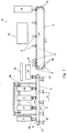
- the described embodiment comprises a bag magazine 7, an opening station 8, a filling station 9 and a closing station 10, which is above the first conveyor 6 are arranged.
- the conveyor 6 serves rows of Feed foil bags 1 to these treatment stations. Since FIG. 1 is a side view, only the first film bag in a row is closed see.
- the individual treatment stations each extend over the whole range of plastic bags.
- the known foil bags 1 are e.g. made of aluminum laminate film. Two Foils are welded together on three sides, while one on the fourth side Bottom part is inserted. In this way, the foil bag expands downwards to a standing area. In the unfilled state, the top edge of the bag 1 is still unwelded.
- Transport elements 2 are located on the conveyor 6 at a distance a in the conveying direction to each other.
- the individual transport elements include themselves known molded parts 2a, which are used to hold the film bag in an upright position or support the opening and closing process.
- the conveyor 6 with the transport elements 2 runs around deflection rollers 17 and forms in this way Endless belt.
- the opening station 8, the filling station 9 and the closing station 10 are in one Fixed frame 16, which is adjustable in height.
- a transfer station 11 which connects to the sealed film bags passes on a second conveyor 5.
- This second conveyor 5 leads by a cooling station 12, e.g. is formed by ventilation cooling. It however, other cooling mechanisms, e.g. appropriate cold zones or a water cooling 13 can be provided.
- Figure 1 shows e.g. schematically one Ventilation cooling 13.
- the second conveyor 5 On the second conveyor 5 transport elements 3 are attached, one Have a distance b between each other in the conveying direction that is smaller than the distance a of the transport elements 2 on the first conveyor 6.
- the second conveyor 5 is an endless belt which is fed back around the deflection rollers 18. in the Connection to the cooling station 12 is followed by a removal device 14.
- Both the first and the second transport elements (2, 3) are each in rows arranged side by side, of which in the side view of Figure 1 only that first one is visible.
- the foil bags used in such a range of transport elements are guided side by side through the treatment stations subjected to the respective treatment stations simultaneously.
- the figures show the For the sake of clarity, not all transport elements, the successive treatment stations be fed. Transport elements, not shown, are e.g. at the second conveyor identified by a dashed line.
- Figure 2 shows a schematic representation of a detailed section from Figure 1 with the transfer station 11.
- Carrying elements 20 are height-adjustable elements 21 attached to the Bottom end are clamps 22a, 22b, which hold the foil bags 1, 4 serve.
- These height adjustable elements 21 are e.g. Pneumatic cylinder or rotating spindles with corresponding thread counterparts.
- the other elements correspond to the Elements described with reference to Figure 1 and have the same reference numerals described. The movement of the individual elements and the foil bags in the Transfer area is also shown by arrows.
- an empty foil bag is taken from the magazine 7 by a transport element 2.
- the film bag is standing in guided a transport element. He is upright from elements 2a in Position held. Due to the cyclical movement of the conveyor 6 a film bag is guided to the opening station 8.
- In this opening station 8 Inflate the foil pouch with the help of an inserted tube.
- the film bag must be slightly opened at its upper edge become. This will e.g. achieved with a suction device, which is not shown in Figure 1 is, and laterally engages the upper edge of the film bag and pulls it apart.
- the film bag inflated in this way is conveyed further to the filling station 9.
- the foil pouch filled in this way is located below the closing station 10.
- the upper edges of the side surfaces must be brought together again. This can e.g. by loosening the suction devices that are used for opening take care of the foil bag in the opening station 8.
- Both the opening station, the The filling station and the closing station are different in height Customizable bag.
- an adjustable gesture 16 is provided. After closing in the sealing station 10, the film bags are transferred from the transfer device 11 from the first conveyor 6 to the second conveyor 5 spent.
- the transport elements 2 of the first conveyor device 6 are for receiving a new foil bag from magazine 7 with the aid of the deflection rollers 17 returned.
- FIG. 2 shows how the transfer device is designed in this embodiment is.
- the control of the entire transfer device 11 with the drives the brackets 22a, 22b, the height-adjustable elements 21 and the support elements 20 is taken over by a process computer.
- the foil bag 1 will from the first conveyor 6 in the support elements 2 of the transfer device 11 fed.
- clips 22a grip the foil bags in the upper region 1 on.
- Height-adjustable elements 21 pull the foil bag upwards while at the same time a horizontal movement of the support elements 20 on the support rail 19 is triggered.
- Both the vertical movement of the height adjustable elements 21 and the horizontal movement of the support members 20 is driven caused by the automatic control of the transfer device 11 be managed.
- drive means not explicitly shown in FIG. 2 are provided, e.g. Pneumatic cylinder or spindle gear, which in a known manner function.
- the transfer device Rows of foil bags treated simultaneously.
- the foil bags in the Brought area of the second conveyor 5.
- the clips 22b open and give the foil pouch in the transport elements 3 of the second conveyor 5 free.
- the second conveyor device 5 brings the filled film bags 4 to a ventilation cooling station 13.
- the speed of the second conveyor device 5 is lower than the speed of the first conveyor 6.
- FIG. 1 it can be seen how the second conveyor device 5 moves the rows of Foil bags 4 leads through the cooling station 12. Because of the lower speed the second conveyor 5, the film bags 4 are sufficient Time in the refrigerated area, even if the entire cooling station 12 is shorter is as in prior art filling machines.
- the rows of film bags are finally one Withdrawal station 14 for further transport or for packaging in no longer of interest Taken from the second conveyor 5.
- the filling machine according to the invention with two separate conveying devices 5, 6 enables individual control of the speed at which the foil bags be fed to the individual treatment stations or the cooling station. To this Way can e.g. a slower speed in the area of the cooling station realize without the fast work cycle in the area of opening, filling or Capping station would have to be abandoned.
- a separate conveyor for cooling is provided by with much simpler designed conveyor elements , the total number of complicated ones required in the machine Transport elements less because these only in the area of the first conveyor is required for the stations passed through there.
Abstract
Description
Die Erfindung betrifft eine Füllmaschine für flexible Folienbeutel mit einer Transporteinrichtung, die eine Vielzahl Von Transportelementen für Folienbeutel umfaßt, zur Zuführung der Folienbeutel zu einer Öffnungsstation, einer Füllstation, einer Verschließstation und einer Kühlstation entsprechend dem Oberbegriff des Anspruchs 1 und ein Verfahren zum Öffnen, Füllen, Verschließen und Kühlen von Folienbeuteln.The invention relates to a filling machine for flexible film bags with a transport device, which comprises a plurality of transport elements for foil bags, for feeding the foil bags to an opening station, a filling station, a closing station and a cooling station according to the preamble of claim 1 and a method for opening, filling, closing and cooling foil bags.
Um flexible Folienbeutel mehreren Behandlungsschritten, wie z.B. Ausbilden einer Beutelöffnung, Befüllen mit Füllgut, Versiegelung bzw. Verschließen und Kühlung zu unterziehen, ist es bekannt, die Folienbeutel mit Hilfe von Transportelementen an entsprechenden Behandlungsstationen vorbeizuführen.To handle flexible foil bags in several treatment steps, e.g. Train one Bag opening, filling with contents, sealing or closing and cooling undergo, it is known to attach the foil bag with the help of transport elements bring the appropriate treatment stations past.
Speziell in ungefülltem Zustand haben die Folienbeutel eine geringe Steifigkeit und müssen deswegen in geeigneter Position gehalten werden. Dazu müssen die Transportelemente entsprechende Haltevorrichtungen aufweisen. Außerdem müssen die Folienbeutel in der entsprechenden Behandlungsstation geöffnet werden, um mit Füllgut gefüllt zu werden bzw. im Anschluß daran wieder verschlossen werden. Dazu müssen die Transportelemente entsprechende Formungsteile aufweisen. Um alle diese erwähnten Aufgaben erfüllen zu können, benötigen bekannte Transportelemente daher mehr oder weniger aufwendige Konstruktionsteile mit entsprechenden Dimensionen.Especially in the unfilled state, the foil bags have a low rigidity and must therefore be kept in a suitable position. To do this, the transport elements have corresponding holding devices. They also have to Foil bags can be opened in the appropriate treatment station with Filled goods to be filled or then closed again. To the transport elements must have corresponding molded parts. To everyone Known transport elements are required to be able to fulfill these mentioned tasks therefore more or less complex construction parts with corresponding dimensions.
In einer sogen. Reihentaktmaschine werden mehrere Beutel in quer zur Transportrichtung verlaufenden Reihen gleichzeitig behandelt. Dazu ist eine Transporteinrichtung vorgesehen, die die Folienbeutel in den entsprechenden Transportelementen an den Behandlungsstationen taktweise vorbeiführt. Auf der Transporteinrichtung befinden sich im Betrieb mehrere Folienbeutel jeweils in einer Reihe quer zur der Bewegungsrichtung nebeneinander. Eine solche Reihe wird immer zum selben Zeitpunkt einem bestimmten Behandlungsschritt unterzogen. Die in Bewegungsrichtung darauffolgende Reihe von Folienbeuteln wird einem vorhergehenden Behandlungsschritt unterzogen. Der Abstand der einzelnen Transportelemente auf der Fördereinrichtung ist dementsprechend auf den Abstand der einzelnen Behandlungsstationen einerseits und den Dimensionen der Transportelemente andererseits abgestimmt.In a so-called Row cycle machines are several bags in the cross direction of transport trending rows treated simultaneously. There is a transport device for this provided that the foil bag in the appropriate transport elements past the treatment stations in cycles. On the transport device there are several foil bags in operation in a row transverse to the direction of movement side by side. Such a series is always at the same time undergone a certain treatment step. The one in the direction of movement Subsequent series of foil bags becomes a previous treatment step subjected. The distance between the individual transport elements on the conveyor is accordingly on the distance of the individual treatment stations on the one hand and the dimensions of the transport elements on the other.
Bei einer bekannten Füllmaschine werden die Transportelemente mit den darin befindlichen Folienbeuteln von einer Transporteinrichtung zunächst unter einer Öffnungsstation, einer Füllstation und einer Verschließstation entlanggeführt. Im weiteren Verlauf werden die Folienbeutel einer Kühlstation zugeführt, um die Folienbeutel nach der Füllung, z.B. mit heißem Füllgut, abzukühlen.In a known filling machine, the transport elements with those located therein Foil bags from a transport device first under an opening station, guided along a filling station and a closing station. In the further The film bags are fed to a cooling station around the film bags after filling, e.g. with hot filling, cool down.
Damit eine ausreichende Kühlung erreicht werden kann, müssen sich die Folienbeutel eine ausreichende Zeit lang in der Kühlstation befinden. Dazu muß die Transporteinrichtung entweder langsam genug betrieben werden oder diskontinuierlich, was zu einer unerwünschten Reduktion des Gesamtdurchsatzes führt. Werden die Folienbeutel der Kühlstation in den Transportelementen zugeführt, so bedingt dies eine große Anzahl derartiger Transportelemente. Da diese Transportelemente, wie beschrieben, einen komplizierten Aufbau mit entsprechenden Formungsteilen aufweisen, ist eine derartige Behälterfüllmaschine kostenintensiv.In order for sufficient cooling to be achieved, the foil bags must be be in the cooling station for a sufficient time. To do this, the transport device either run slowly enough or intermittently what leads to an undesirable reduction in total throughput. Become the foil pouch fed to the cooling station in the transport elements, this requires one large number of such transport elements. Since these transport elements, as described, have a complicated structure with corresponding molded parts, such a container filling machine is expensive.
Aufgabe der vorliegenden Erfindung ist es, eine Füllmaschine für flexible Folienbeutel zur Verfügung zu stellen, die trotz hoher Leistung einfacher und damit kostengünstiger insbesondere in der Herstellung ist.The object of the present invention is a filling machine for flexible film bags to make available that, despite high performance, easier and therefore cheaper especially in the manufacture.
Diese Aufgabe wird bei einer gattungsgemäßen Füllmaschine für Folienbeutel mit
den Merkmalen des kennzeichnenden Teils des Anspruchs 1 und durch ein Verfahren
mit den Merkmalen des Anspruchs 9 gelöst. Vorteilhafte Ausgestaltungen sind
Gegenstand der Unteransprüche.This task is performed with a generic filling machine for foil bags
the features of the characterizing part of claim 1 and by a method
solved with the features of
Bei einer erfindungsgemäßen Füllmaschine umfaßt die Transporteinrichtung eine erste Fördereinrichtung mit einer Vielzahl von ersten Transportelementen zur Zuführung von Folienbeuteln zur Öffnungsstation, der Füllstation und der Verschließstation, und eine zweite Fördereinrichtung mit einer Vielzahl von Zweiten Transportelementen zur Zuführung der Folienbeutel zur Kühlstation, und eine Übergabestation zur Übergabe der Folienbeutel von der ersten Fördereinrichtung zur zweiten Fördereinrichtung.In a filling machine according to the invention, the transport device comprises a first conveyor with a plurality of first transport elements for feeding from plastic bags to the opening station, the filling station and the closing station, and a second conveyor with a plurality of second transport elements for feeding the foil bags to the cooling station, and a transfer station for transfer the film bag from the first conveyor to the second conveyor.
Mit Hilfe zweier unabhängiger Fördereinrichtungen ist es möglich, die Geschwindigkeit bzw. den Takt, mit der die Folienbeutel an den entsprechenden Behandlungsstationen bzw. der Kühlstation vorbeigeführt werden, individuell zu regeln. Ein schneller Arbeitstakt, der z.B. bei der Öffnungs-, Füll- und der Verschließstation möglich ist, bedingt nicht notwendigerweise einen schnellen Arbeitstakt bzw. eine hohe Geschwindigkeit, wenn die Folienbeutel die Kühlstation passieren. Zudem können die zweiten Transportelemente der zweiten Fördereinrichtung einfacher gestaltet sein, da in der Kühlstation keine Öffnungs- bzw. Schließfunktionen mehr durchgeführt werden müssen. Die Folienbeutel sind in der Kühlstation bereits gefüllt, so daß sie auch eine ausreichende Eigenstabilität haben und keine aufwendigen Haltevorrichtungen in den Transportelementen vorgesehen sein müssen. Auf diese Weise ergibt sich die Möglichkeit, die zweiten Transportelemente, die die Folienbeutel der Kühlstation zuführen, einfacher zu gestalten, so daß die Anzahl der notwendigen, komplizierter aufgebauten Transportelemente erheblich verringert werden kann.With the help of two independent conveyors, it is possible to control the speed or the rhythm with which the foil bags at the corresponding treatment stations or the cooling station are guided to regulate individually. A quick one Work cycle, e.g. is possible at the opening, filling and closing station, does not necessarily require a fast work cycle or high speed, when the foil bags pass the cooling station. In addition, the second transport elements of the second conveyor can be made simpler because no opening or closing functions are carried out in the cooling station have to. The foil bags are already filled in the cooling station, so that they are also one have sufficient inherent stability and no expensive holding devices in the Transport elements must be provided. In this way there is the possibility the second transport elements, which feed the foil bags to the cooling station, easier to design, so that the number of necessary, more complicated Transport elements can be significantly reduced.
Vorteilhafterweise wird die zweite Fördereinrichtung mit einer kleineren Geschwindigkeit betrieben als die erste Fördereinrichtung. Eine kleinere Geschwindigkeit der zweiten Fördereinrichtung bedeutet eine längere Aufenthaltsdauer der Folienbeutel im Bereich der Kühlstation, was die Kühleffektivität erhöht.The second conveyor is advantageously driven at a lower speed operated as the first conveyor. A lower speed of second conveyor means a longer duration of stay of the foil bags in the area of the cooling station, which increases the cooling effectiveness.
In weiterer vorteilhafter Ausgestaltung weisen die zweiten Transportelemente der zweiten Fördereinrichtung einen kleineren Abstand in Förderrichtung zueinander auf als die ersten Transportelemente in der ersten Fördereinrichtung. Wenn die zweite Fördereinrichtung mit langsamerer Geschwindigkeit betrieben wird als die erste Fördereinrichtung, so kann durch eine kleinere Beabstandung gewährleistet werden, daß die mit einem schnelleren Takt von der ersten Fördereinrichtung zugeführten Folienbeutel von der zweiten Fördereinrichtung trotz der geringeren Geschwindigkeit wegbefördert werden. Auf diese Art und Weise kann die Maschine mit einer sehr hohen Leistung betrieben werden, die im wesentlichen durch den Arbeitstakt der ersten Fördereinrichtung bestimmt wird. Im Kühlbereich entsteht dann keine den Durchsatz vermindernde Engstelle.In a further advantageous embodiment, the second transport elements have the second conveyor a smaller distance from each other in the conveying direction than the first transport elements in the first conveyor. If the second Conveyor is operated at a slower speed than the first conveyor, it can be ensured by a smaller spacing that the film bags fed from the first conveyor device at a faster cycle transported away from the second conveyor despite the lower speed become. In this way, the machine can operate at a very high Power operated essentially by the work cycle of the first Conveyor is determined. Then there is no throughput in the cooling area reducing constriction.
In vorteilhafter Ausgestaltung ist die Arbeitshöhe der Öffnungsstation, der Füllstation und der Verschließstation einstellbar, um die Vorrichtung auf verschieden hohe Folienbeutel einrichten zu können.In an advantageous embodiment, the working height of the opening station, the filling station and the closing station adjustable to the device on different height foil bags to be able to set up.
In einer besonders vorteilhaften Ausführungsform umfaßt die Füllmaschine eine Plattform im Übergangsbereich zwischen der ersten und der zweiten Fördereinrichtung. Eine solche Plattform ermöglicht eine leichte Wartung bzw. Überwachung der einzelnen Behandlungsstationen bzw. -operationen.In a particularly advantageous embodiment, the filling machine comprises a Platform in the transition area between the first and the second conveyor. Such a platform enables easy maintenance or monitoring of the individual treatment stations or operations.
In einer Ausführungsform umfaßt die Übergabestation höhenveränderliche und laterial verschiebbare Elemente, die Klammern haltern, mit deren Hilfe die Folienbeutel von der ersten Fördereinrichtung zur zweiten Fördereinrichtung befördert werden. Vorteilhafterweise ist dazu eine automatische Steuerung vorgesehen.In one embodiment, the transfer station comprises variable-height and material Slidable elements that hold the clips with the help of the foil bags are conveyed from the first conveyor to the second conveyor. An automatic control is advantageously provided for this.
Im folgenden wird anhand der Figuren eine Ausführungsform einer erfindungsgemäßen Füllmaschine und deren Funktionsweise beschrieben.In the following, an embodiment of the invention is described with reference to the figures Filling machine and how it works.
Dabei zeigt
- Figur 1
- eine schematische Seitenansicht einer erfindungsgemäßen Füllmaschine und
Figur 2- eine schematische Seitenansicht des Übergabebereiches einer erfindungsgemäßen Füllmaschine.
- Figure 1
- is a schematic side view of a filling machine according to the invention and
- Figure 2
- is a schematic side view of the transfer area of a filling machine according to the invention.
Die beschriebene Ausführungsform umfaßt ein Beutelmagazin 7, eine Öffnungsstation
8, eine Füllstation 9 und eine Verschließstation 10, die oberhalb der ersten Fördereinrichtung
6 angeordnet sind. Die Fördereinrichtung 6 dient dazu, Reihen von
Folienbeuteln 1 diesen Behandlungsstationen zuzuführen. Da es sich bei der Figur 1
um eine Seitenansicht handelt, ist jeweils nur der erste Folienbeutel einer Reihe zu
sehen. Die einzelnen Behandlungsstationen erstrecken sich dabei jeweils über die
ganze Reihe von Folienbeuteln.The described embodiment comprises a
Die an sich bekannten Folienbeutel 1 bestehen z.B. aus Aluminiumlaminatfolie. Zwei Folien sind an drei Seiten miteinander verschweißt, während an der vierten Seite ein Bodenteil eingesetzt ist. Auf diese Weise erweitert sich der Folienbeutel nach unten zu einer Stndfläche. Im ungefüllten Zustand ist die Oberkante des Beutels 1 noch unverschweißt.The known foil bags 1 are e.g. made of aluminum laminate film. Two Foils are welded together on three sides, while one on the fourth side Bottom part is inserted. In this way, the foil bag expands downwards to a standing area. In the unfilled state, the top edge of the bag 1 is still unwelded.
Auf der Fördereinrichtung 6 befinden sich Transportelemente 2 mit einem Abstand a
in Förderrichtung zueinander. Die einzelnen Transportelemente umfassen an sich
bekannte Formteile 2a, die zum Halten der Folienbeutel in aufrechter Position dienen
bzw. den Öffnungs- und Verschließvorgang unterstützen. Die Fördereinrichtung 6 mit
den Transportelementen 2 läuft um Umlenkrollen 17 und bildet auf diese Weise ein
Endlosband.
Die Öffnungsstation 8, die Füllstation 9 und die Verschließstation 10 sind an einem
Gestell 16 befestigt, das höhenverstellbar ist. Im Anschluß an die Verschließstation
10 schließt sich eine Übergabestation 11 an, die die verschlossenen Folienbeutel an
eine zweite Fördereinrichtung 5 weitergibt. Diese zweite Fördereinrichtung 5 führt
durch eine Kühlstation 12, die z.B. durch eine Ventilationskühlung gebildet wird. Es
können jedoch auch andere Kühlmechanismen, wie z.B. entsprechende Kältezonen
oder eine Wasserkühlung 13 vorgesehen sein. Figur 1 zeigt z.B. schematisch eine
Ventilationskühlung 13.The
An der zweiten Fördereinrichtung 5 sind Transportelemente 3 befestigt, die einen
Abstand b untereinander in Förderrichtung haben, der kleiner ist als der Abstand a
der Transportelemente 2 auf der ersten Fördereinrichtung 6. Die zweite Fördereinrichtung
5 ist ein Endlosband, das um die Umlenkrollen 18 zurückgeführt wird. Im
Anschluß an die Kühlstation 12 schließt sich eine Entnahmevorrichtung 14 an.On the
Sowohl die ersten als auch die zweiten Transportelemente (2, 3) sind jeweils in Reihen nebeneinander angeordnet, von denen in der Seitenansicht der Figur 1 nur das jeweils erste sichtbar ist. Die Folienbeutel, die in einer solchen Reihe von Transportelementen nebeneinander durch die Behandlungsstationen geführt werden, werden den jeweiligen Behandlungsstationen gleichzeitig unterzogen. Die Figuren zeigen der Übersichtlichkeit halber nicht alle Transportelemente, die nacheinander den Behandlungsstationen zugeführt werden. Nicht gezeigte Transportelemente sind z.B.- bei der zweiten Fördereinrichtung durch eine Strichlinie gekennzeichnet.Both the first and the second transport elements (2, 3) are each in rows arranged side by side, of which in the side view of Figure 1 only that first one is visible. The foil bags used in such a range of transport elements are guided side by side through the treatment stations subjected to the respective treatment stations simultaneously. The figures show the For the sake of clarity, not all transport elements, the successive treatment stations be fed. Transport elements, not shown, are e.g. at the second conveyor identified by a dashed line.
Im Übergabebereich zwischen der ersten und der zweiten Fördereinrichtung befindet
sich oberhalb der Übergabevorrichtung 11 eine Wartungs- und Überwachungsplattform
15.Located in the transfer area between the first and the second conveyor
there is a maintenance and monitoring platform above the
Die Bewegungsrichtungen sowohl der ersten Fördereinrichtung 6 als auch der zweiten
Fördereinrichtung 5 sind durch Pfeile angeordnet.The directions of movement of both the
Figur 2 zeigt in schematischer Darstellung einen detaillierten Ausschnitt aus Figur 1
mit der Übergabestation 11.Figure 2 shows a schematic representation of a detailed section from Figure 1
with the
An einem Träger 19 befinden sich horizontal bewegliche Trageelemente 20. An diesen
Trageelementen 20 sind höhenveränderliche Elemente 21 befestigt, an deren
unterem Ende sich Klammern 22a, 22b anschließen, die zur Aufnahme der Folienbeutel
1, 4 dienen. Diese höhenverstellbaren Elemente 21 sind z.B. Pneumatikzylinder
oder drehbare Spindeln mit ensprechenden Gewindegegenstücken. Es sind jedoch
auch andere Realisierungen möglich. Die weiteren Elemente entsprechen den
mit Bezug zu Figur 1 beschriebenen Elementen und sind mit den gleichen Bezugsziffern
beschrieben. Die Bewegung der einzelnen Elemente und der Folienbeutel im
Übergabebereich ist ebenso durch Pfeile dargestellt.There are horizontally
Im folgenden wird die Funktionsweise der beschriebenen Ausführungsform erläutert. Dabei wird die Arbeitsweise am Durchgang eines Folienbeutels einer Reihe durch die Behandlungsstationen beschreiben.The operation of the described embodiment is explained below. The procedure for the passage of a film bag in a row is shown by the Describe treatment stations.
Durch einen nicht näher gezeigten Mechanismus, z.B. durch eine Saugvorrichtung,
wird aus dem Magazin 7 ein leerer Folienbeutel von einem Transportelement 2 übernommen.
Bei der beschriebenen Ausführungsform wird der Folienbeutel stehend in
einem Transportelement geführt. Dabei wird er von den Elementen 2a in aufrechter
Stellung gehalten. Durch die taktweise Fortbewegung der Fördereinrichtung 6 wird
ein Folienbeutel zu der Öffnungsstation 8 geführt. In dieser Öffnungsstation 8 wird der
Folienbeutel mit Hilfe eines eingeführten Röhrchens aufgeblasen. Um dieses Blasrohr
einführen zu können, muß der Folienbeutel an seiner Oberkante leicht geöffnet
werden. Dies wird z.B. mit einer Saugvorrichtung erreicht, die in der Figur 1 nicht gezeigt
ist, und seitlich an die Oberkante der Folienbeutel angreift und diese auseinanderzieht.
Der so aufgeblasene Folienbeutel wird zur Füllstation 9 weitergefördert. Dort
wird im allgemeinen heißes Gut, z.B. Getränk, eingefüllt. Einen weiteren Arbeitstakt
später befindet sich der so gefüllte Folienbeutel unterhalb der Verschließstation 10.
Um die Oberkante des Folienbeutels in der Verschließstation verschweißen zu können,
müssen die Oberkanten der Seitenflächen wieder zueinander geführt werden.
Dies kann z.B. durch Lösen der Saugvorrichtungen geschehen, die für die Öffnung
der Folienbeutel in der Öffnungsstation 8 sorgen. Sowohl die Öffnungsstation, die
Füllstation als auch die Verschließstation sind in der Höhe an die verschiedenen
Beutel anpaßbar. Dazu ist ein verstellbares Geste 16 vorgesehen. Nach dem Verschließen
in der Verschließstation 10 werden die Folienbeutel von der Übergabevorrichtung
11 von der ersten Fördereinrichtung 6 auf die zweite Fördereinrichtung 5
verbracht. Die Transportelemente 2 der ersten Fördereinrichtung 6 werden zur Aufnahme
eines neuen Folienbeutels aus dem Magazin 7 mit Hilfe der Umlenkrollen 17
zurückgeführt.By a mechanism, not shown, e.g. through a suction device,
an empty foil bag is taken from the
In Figur 2 ist gezeigt, wie bei dieser Ausführungsform die Übergabevorrichtung ausgestaltet
ist. Die Steuerung der gesamten Übergabevorrichtung 11 mit den Antrieben
der Klammern 22a, 22b, der höhenverstellbaren Elemente 21 und der Trägerelemente
20 wird dabei von einem Prozeßrechner übernommen. Die Folienbeutel 1 werden
von der ersten Fördereinrichtung 6 in den Trageelementen 2 der Übergabevorrichtung
11 zugeführt. Dort greifen Klammern 22a im oberen Bereich an die Folienbeutel
1 an. Höhenverstellbare Elemente 21 ziehen den Folienbeutel nach oben, während
gleichzeitig eine horizontale Bewegung der Trageelemente 20 an der Trageschiene
19 ausgelöst wird. Sowohl die vertikale Bewegung der höhenverstellbaren Elemente
21 als auch die horizontale Bewegung der Trageelemente 20 wird durch Antriebe
hervorgerufen, die von der automatischen Steuerung der Übergabevorrichtung 11
geregelt werden. Dazu sind in der Figur 2 nicht explizit gezeigte Antriebsmittel vorgesehen,
z.B. Pneumatikzylinder oder Spindelgetriebe, die in an sich bekannter Weise
funktionieren.FIG. 2 shows how the transfer device is designed in this embodiment
is. The control of the
Ebenso wie in den anderen Behandlungsstationen werden auch in der Übergabevorrichtung
Reihen von Folienbeuteln gleichzeitig behandelt. Durch die horizontale Bewegung
des Trageelementes 20 der Schiene 19 werden die Folienbeutel in den
Bereich der zweiten Fördereinrichtung 5 gebracht. Dort werden sie durch Absenken
der höhenverstellbaren Elemente 21 in die Transportelemente 3 der zweiten Fördereinrichtung
5 abgestellt. Die Klammern 22b öffnen sich und geben die Folienbeutel
in die Transportelemente 3 der zweiten Fördereinrichtung 5 frei.Just as in the other treatment stations, the transfer device
Rows of foil bags treated simultaneously. Through the horizontal movement
of the
Die zweite Fördereinrichtung 5 bringt die gefüllten Folienbeutel 4 zu einer Ventilationskühlstation
13. Die Geschwindigkeit der zweiten Födereinrichtung 5 ist geringer
als die Geschwindigkeit der ersten Fördereinrichtung 6. Um den Arbeitstakt der ersten
Fördereinrichtung 6 auch an der zweiten Fördereinrichtung 5 beibehalten zu
können, ist der Abstand b der einzelnen Transportelemente 3 auf der zweiten Fördereinrichtung
5 in Förderrichtung kleiner als der Abstand a der einzelnen Transportelemente
2 auf der ersten Fördereinrichtung 6. Auf diese Weise kann die geringere
Geschwindigkeit der zweiten Fördereinrichtung 5 ausgeglichen werden. Da sich die
Folienbeutel 4 auf der zweiten Fördereinrichtung 5 bereits in gefülltem Zustand befinden
und dementsprechend ausreichend stabil sind, brauchen sie keine aufwendige
Unterstützung, um sie senkrecht zu halten. Dementsprechend können die zweiten
Transportelemente 3 auf der zweiten Fördereinrichtung 5 weniger aufwendig und
weniger Platz beanspruchend konstruiert sein als die ersten Transportelemente 2 auf
der ersten Fördereinrichtung 6. Wie in Figur 2 dargestellt, können die Transportelemente
3 der zweiten Fördereinrichtung 5 einfache wannenförmige Elemente sein.The
Wiederum in Figur 1 ist erkennbar, wie die zweite Fördereinrichtung 5 die Reihen von
Folienbeuteln 4 durch die Kühlstation 12 führt. Aufgrund der geringeren Geschwindigkeit
der zweiten Fördereinrichtung 5 befinden sich die Folienbeutel 4 eine ausreichende
Zeit im gekühlten Bereich, auch wenn die gesamte Kühlstation 12 kürzer gestaltet
ist als bei Füllmaschinen des Standes der Technik.Again in FIG. 1 it can be seen how the
Am Ende der Kühlstation 12 werden schließlich die Reihen der Folienbeutel von einer
Entnahmestation 14 zum Weitertransport bzw. zur Verpackung in nicht weiter interessierender
Weise von der zweiten Fördereinrichtung 5 entnommen.At the end of the
Die erfindungsgemäße Füllmaschine mit zwei separaten Fördereinrichtungen 5, 6
ermöglicht eine individuelle Steuerung der Geschwindigkeit, mit der die Folienbeutel
den einzelnen Behandlungsstationen bzw. der Kühlstation zugeführt werden. Auf diese
Weise läßt sich z.B. eine langsamere Geschwindigkeit im Bereich der Kühlstation
realisieren, ohne daß der schnelle Arbeitstakt im Bereich der Öffnungs-, Füll- bzw.
Verschließstation aufgegeben werden müßte. Da für die Kühlung eine separate Fördereinrichtung
vorgesehen ist, die durch mit wesentlich einfacher gestalteten Förderelementen
auskommt, ist insgesamt die in der Maschine benötigte Anzahl von komplizierten
Transportelementen geringer, weil diese nur im Bereich der ersten Fördereinrichtung
für die dort durchlaufenen Stationen benötigt wird.The filling machine according to the invention with two separate conveying
Insgesamt läßt sich die Maschine somit bei vergleichbarer Leistung wesentlich kostengünstiger herstellen und ist letztlich auch in der Wartung weniger aufwendig als bekannte Maschinen.Overall, the machine can thus be compared to a comparable performance much cheaper manufacture and is ultimately less expensive than maintenance known machines.
Claims (9)
dadurch gekennzeichnet, daß
characterized in that
dadurch gekennzeichnet, daß
characterized in that
dadurch gekennzeichnet, daß
characterized in that
dadurch gekennzeichnet, daß
characterized in that
dadurch gekennzeichnet, daß
characterized in that
gekennzeichnet durch
marked by
dadurch gekennzeichnet, daß
characterized in that
gekennzeichnet durch
marked by
dadurch gekennzeichnet, daß
characterized in that
Priority Applications (1)
| Application Number | Priority Date | Filing Date | Title |
|---|---|---|---|
| SI9830838T SI0909708T1 (en) | 1997-10-16 | 1998-09-15 | Containers filling machine |
Applications Claiming Priority (2)
| Application Number | Priority Date | Filing Date | Title |
|---|---|---|---|
| DE19745852A DE19745852B4 (en) | 1997-10-16 | 1997-10-16 | Foil bag filling machine and foil bag filling process |
| DE19745852 | 1997-10-16 |
Publications (2)
| Publication Number | Publication Date |
|---|---|
| EP0909708A1 true EP0909708A1 (en) | 1999-04-21 |
| EP0909708B1 EP0909708B1 (en) | 2006-05-24 |
Family
ID=7845796
Family Applications (1)
| Application Number | Title | Priority Date | Filing Date |
|---|---|---|---|
| EP98117495A Expired - Lifetime EP0909708B1 (en) | 1997-10-16 | 1998-09-15 | Containers filling machine |
Country Status (27)
| Country | Link |
|---|---|
| US (1) | US6189293B1 (en) |
| EP (1) | EP0909708B1 (en) |
| JP (1) | JP3195936B2 (en) |
| KR (1) | KR100290756B1 (en) |
| CN (1) | CN1079351C (en) |
| AT (1) | ATE327160T1 (en) |
| BG (1) | BG63999B1 (en) |
| BR (1) | BR9804501A (en) |
| CA (1) | CA2249176C (en) |
| CY (1) | CY1105156T1 (en) |
| CZ (1) | CZ296795B6 (en) |
| DE (2) | DE19745852B4 (en) |
| DK (1) | DK0909708T3 (en) |
| ES (1) | ES2264179T3 (en) |
| HK (1) | HK1020556A1 (en) |
| HR (1) | HRP980549A2 (en) |
| HU (1) | HUP9802396A3 (en) |
| ID (1) | ID21097A (en) |
| PL (1) | PL187928B1 (en) |
| PT (1) | PT909708E (en) |
| SA (1) | SA98190880B1 (en) |
| SI (1) | SI0909708T1 (en) |
| SK (1) | SK142998A3 (en) |
| TR (1) | TR199802093A2 (en) |
| TW (1) | TW396135B (en) |
| YU (1) | YU45498A (en) |
| ZA (1) | ZA988979B (en) |
Cited By (1)
| Publication number | Priority date | Publication date | Assignee | Title |
|---|---|---|---|---|
| CN101898741A (en) * | 2009-09-29 | 2010-12-01 | 陈刚 | Opening, loading, filling and sealing integrated machine for internal lining bag of barreled water |
Families Citing this family (22)
| Publication number | Priority date | Publication date | Assignee | Title |
|---|---|---|---|---|
| DE19952006A1 (en) | 1999-10-28 | 2001-05-10 | Indag Gmbh | Procedure for handling stand-up pouches |
| DE19955830A1 (en) * | 1999-11-20 | 2001-05-23 | Boehl Gmbh H | Object wrapping method has wrapping band used for supporting object during transfer between spaced transport bands on opposite sides of wrapping station |
| DE10146487B4 (en) * | 2001-09-20 | 2009-08-27 | Fresenius Kabi Deutschland Gmbh | Apparatus for the continuous dispensing of bags with spouts |
| US8381534B2 (en) * | 2007-05-31 | 2013-02-26 | Reddy Ice Corporation | Ice distribution system and method |
| US8468784B2 (en) | 2010-02-02 | 2013-06-25 | Reddy Ice Corporation | Ice bagging system including auxiliary source of bags |
| WO2005051806A2 (en) * | 2003-11-25 | 2005-06-09 | Hauni Primary Gmbh | Handling device for a container used in the tobacco industry |
| DE10360082A1 (en) * | 2003-12-20 | 2005-07-21 | Robert Bosch Gmbh | Installation for processing containers, in particular, containers used in the pharmaceutical industry comprises treatment stations, buffer zones and at least two circulating transport units with separate drives |
| US7363753B2 (en) * | 2005-01-22 | 2008-04-29 | Gates Automation, Inc. | Method for removing a pouch from a plurality of pouches including bending and pulling of the pouch |
| DE102006038707A1 (en) * | 2006-08-18 | 2008-02-21 | Khs Ag | Device for the treatment of flexible, tube-like structures |
| AT10632U1 (en) * | 2008-04-07 | 2009-07-15 | Statec Anlagentechnik Gmbh | DEVICE FOR FILLING SAWS |
| TWI472459B (en) * | 2008-05-19 | 2015-02-11 | Melrose David | Headspace modification method for removal of vaccum pressure and apparatus therefor |
| DE102008048812A1 (en) * | 2008-09-24 | 2010-04-01 | Khs Ag | Method and device for the combined production and filling of plastic containers |
| ES2623871T3 (en) * | 2009-12-22 | 2017-07-12 | Premier Tech Technologies Ltée | Robotized transport and transfer system |
| US9890282B2 (en) * | 2014-02-28 | 2018-02-13 | Lg Chem, Ltd. | Flame retardant thermoplastic resin composition and electric wire comprising the same |
| CN106628296A (en) * | 2017-01-21 | 2017-05-10 | 安徽信远包装科技有限公司 | Device for upper pocket, filling, sealing and discharging of high temperature liquid package |
| CN107892035A (en) * | 2017-10-08 | 2018-04-10 | 刘道灵 | A kind of rice-pudding leaf fast package device |
| DE102018212591A1 (en) * | 2018-07-27 | 2020-01-30 | Vanderlande Industries B.V. | Loading station for a pocket conveyor |
| CN108945620B (en) * | 2018-08-02 | 2021-01-12 | 江西天锦农业发展股份有限公司 | Novel beef paste filling equipment in bags |
| IT202000012166A1 (en) * | 2020-05-25 | 2021-11-25 | Perfect Pack S R L | PACKAGING MACHINE |
| CN112078908B (en) * | 2020-07-23 | 2021-11-23 | 浙江小宇科技股份有限公司 | Filling machine |
| CN112061444B (en) * | 2020-09-09 | 2021-12-07 | 台州市亿源塑业有限公司 | Automatic liquid packaging machine |
| CN113636265A (en) * | 2021-08-14 | 2021-11-12 | 浙江珵美科技有限公司 | Encoder 46TO surface mount packaging device and method |
Citations (6)
| Publication number | Priority date | Publication date | Assignee | Title |
|---|---|---|---|---|
| US3941233A (en) * | 1973-05-07 | 1976-03-02 | Franco Aiuola | Apparatus for transferring bodies of delicate consistency from a feed line to a reception line |
| US3961569A (en) * | 1974-08-15 | 1976-06-08 | The United States Of America As Represented By The Secretary Of The Army | Apparatus for continuous microwave sterilization of food in pouches |
| EP0073867A1 (en) * | 1981-08-31 | 1983-03-16 | Société Fournier Frères | Automatic device for loading metal wire containers with horizontal bottles |
| EP0371474A1 (en) * | 1988-11-30 | 1990-06-06 | AZIONARIA COSTRUZIONI MACCHINE AUTOMATICHE-A.C.M.A.-S.p.A. | System for equally spacing and transferring items from a first to a second conveyor |
| US5423414A (en) * | 1994-01-19 | 1995-06-13 | I & H Conveying & Machine Co., Inc. | Evaporative pouch cooler |
| EP0711719A1 (en) * | 1994-11-11 | 1996-05-15 | AZIONARIA COSTRUZIONI MACCHINE AUTOMATICHE-A.C.M.A.-S.p.A. | Equally spaced product conveying method and line |
Family Cites Families (13)
| Publication number | Priority date | Publication date | Assignee | Title |
|---|---|---|---|---|
| US1932683A (en) * | 1932-06-29 | 1933-10-31 | Hazel Atlas Glass Co | Transfer mechanism for glassware |
| US3382644A (en) * | 1963-12-30 | 1968-05-14 | Clarence W. Vogt | Apparatus for and method of continuously forming and filling bags |
| US3340679A (en) * | 1965-02-01 | 1967-09-12 | Bartelt Engineering Co Inc | Apparatus for opening pouches |
| US3494482A (en) * | 1968-02-20 | 1970-02-10 | Riegel Paper Corp | Device for transferring packages |
| US3855907A (en) * | 1973-05-18 | 1974-12-24 | Rexham Corp | Method and machine for forming flat bottom bags having side gussets |
| IT1053104B (en) * | 1975-12-19 | 1981-08-31 | Azionaria Costruzioni Acma Spa | APPARATUS TO TRANSFER ... ACCORDING TO A PREDETERMINED STEP ... OBJECTS TO A RECEIVING CONVEYOR ... THE OBJECTS COMING FROM IRREGULAR INTERVALS FROM A DISPENSING CONVEYOR |
| US4263768A (en) * | 1980-02-07 | 1981-04-28 | Rexham Corporation | Pouch carrier |
| CA1179996A (en) * | 1980-10-17 | 1984-12-27 | Noboru Wakayama | Method and apparatus for automatically and continuously filling and sealing pouches with a filling material |
| JPS5962421A (en) | 1982-10-01 | 1984-04-09 | 東洋製罐株式会社 | Manufacture of filled sealed pouch |
| WO1986000595A1 (en) * | 1984-07-12 | 1986-01-30 | Amf Incorporated | Bag folding mechanism |
| FR2665694B1 (en) * | 1990-08-10 | 1993-07-02 | Marti Sala Jaime | IMPROVEMENTS TO AUTOMATIC VERTICAL POSITIONING MACHINES FOR CONTAINERS. |
| DE4329179A1 (en) * | 1993-08-30 | 1995-03-02 | Kettner Verpackungsmaschf | Machine for transferring articles into a packaging unit |
| IT1280363B1 (en) * | 1995-02-14 | 1998-01-20 | Gd Spa | PRODUCT ADVANCE LINE |
-
1997
- 1997-10-16 DE DE19745852A patent/DE19745852B4/en not_active Expired - Fee Related
-
1998
- 1998-09-15 ES ES98117495T patent/ES2264179T3/en not_active Expired - Lifetime
- 1998-09-15 EP EP98117495A patent/EP0909708B1/en not_active Expired - Lifetime
- 1998-09-15 SI SI9830838T patent/SI0909708T1/en unknown
- 1998-09-15 PT PT98117495T patent/PT909708E/en unknown
- 1998-09-15 DE DE59813547T patent/DE59813547D1/en not_active Expired - Lifetime
- 1998-09-15 AT AT98117495T patent/ATE327160T1/en active
- 1998-09-15 DK DK98117495T patent/DK0909708T3/en active
- 1998-09-30 US US09/163,754 patent/US6189293B1/en not_active Expired - Lifetime
- 1998-10-01 ZA ZA988979A patent/ZA988979B/en unknown
- 1998-10-05 CA CA002249176A patent/CA2249176C/en not_active Expired - Fee Related
- 1998-10-09 TW TW087116843A patent/TW396135B/en not_active IP Right Cessation
- 1998-10-13 HR HR19745852.1A patent/HRP980549A2/en not_active Application Discontinuation
- 1998-10-13 ID IDP981354A patent/ID21097A/en unknown
- 1998-10-14 JP JP29214998A patent/JP3195936B2/en not_active Expired - Fee Related
- 1998-10-14 CZ CZ0331398A patent/CZ296795B6/en not_active IP Right Cessation
- 1998-10-15 PL PL32920998A patent/PL187928B1/en unknown
- 1998-10-15 SK SK1429-98A patent/SK142998A3/en unknown
- 1998-10-15 HU HU9802396A patent/HUP9802396A3/en unknown
- 1998-10-15 BR BR9804501-6A patent/BR9804501A/en not_active IP Right Cessation
- 1998-10-15 KR KR1019980043155A patent/KR100290756B1/en not_active IP Right Cessation
- 1998-10-15 BG BG102852A patent/BG63999B1/en unknown
- 1998-10-16 YU YU45498A patent/YU45498A/en unknown
- 1998-10-16 CN CN98120966A patent/CN1079351C/en not_active Expired - Fee Related
- 1998-10-16 TR TR1998/02093A patent/TR199802093A2/en unknown
- 1998-12-15 SA SA98190880A patent/SA98190880B1/en unknown
-
1999
- 1999-11-01 HK HK99104916A patent/HK1020556A1/en not_active IP Right Cessation
-
2006
- 2006-08-11 CY CY20061101142T patent/CY1105156T1/en unknown
Patent Citations (6)
| Publication number | Priority date | Publication date | Assignee | Title |
|---|---|---|---|---|
| US3941233A (en) * | 1973-05-07 | 1976-03-02 | Franco Aiuola | Apparatus for transferring bodies of delicate consistency from a feed line to a reception line |
| US3961569A (en) * | 1974-08-15 | 1976-06-08 | The United States Of America As Represented By The Secretary Of The Army | Apparatus for continuous microwave sterilization of food in pouches |
| EP0073867A1 (en) * | 1981-08-31 | 1983-03-16 | Société Fournier Frères | Automatic device for loading metal wire containers with horizontal bottles |
| EP0371474A1 (en) * | 1988-11-30 | 1990-06-06 | AZIONARIA COSTRUZIONI MACCHINE AUTOMATICHE-A.C.M.A.-S.p.A. | System for equally spacing and transferring items from a first to a second conveyor |
| US5423414A (en) * | 1994-01-19 | 1995-06-13 | I & H Conveying & Machine Co., Inc. | Evaporative pouch cooler |
| EP0711719A1 (en) * | 1994-11-11 | 1996-05-15 | AZIONARIA COSTRUZIONI MACCHINE AUTOMATICHE-A.C.M.A.-S.p.A. | Equally spaced product conveying method and line |
Cited By (2)
| Publication number | Priority date | Publication date | Assignee | Title |
|---|---|---|---|---|
| CN101898741A (en) * | 2009-09-29 | 2010-12-01 | 陈刚 | Opening, loading, filling and sealing integrated machine for internal lining bag of barreled water |
| CN101898741B (en) * | 2009-09-29 | 2012-04-25 | 陈刚 | Opening, loading, filling and sealing integrated machine for internal lining bag of barreled water |
Also Published As
Similar Documents
| Publication | Publication Date | Title |
|---|---|---|
| EP0909708B1 (en) | Containers filling machine | |
| EP1268319B1 (en) | Conveying device comprising a packages carrier | |
| EP2522581B1 (en) | Workstation for a packaging machine and method for swapping tools | |
| DE60121893T2 (en) | Apparatus and method for feeding bags designed with pouring spouts to a filling machine | |
| DE102004023473B4 (en) | Packaging machine and method for feeding containers in a packaging machine | |
| DE3516651A1 (en) | METHOD AND DEVICE FOR THE TREATMENT OF CRUSHABLE, TUBE-SHAPED CONTAINERS AND THEIR PACKAGING IN BOXES | |
| DE102016207157A1 (en) | A BAG STATION | |
| DE3638806C2 (en) | ||
| EP0621185B1 (en) | Apparatus for conveying and treating packages for liquids | |
| EP0513439A1 (en) | Device for the filling and closing of packages for flowable products | |
| DE4029464C2 (en) | Method and device for discharging package packages from a drawn false twister | |
| DE4116370A1 (en) | Filling and sealing machine for fluid containers - has intermediate transport boxes to process groups of packages simultaneously | |
| DE10356073B4 (en) | Method and device for filling open-top beverage containers | |
| DE102017125973A1 (en) | Process for processing and / or filling of packaging | |
| EP1588946B1 (en) | Method and apparatus for sorting containers in boxes | |
| DE3336109A1 (en) | DEVICE FOR STACKING, TRANSPORTING AND FILLING CONTAINERS | |
| EP1115636B1 (en) | Method and device for supplying, positioning, storing and/or changing containers | |
| EP1871672B1 (en) | Method and system for treating flexible bags | |
| DE4210749C2 (en) | Device for introducing bag packs into a collecting container | |
| EP1129950B1 (en) | Apparatus for removing a bag from a stack of bags | |
| EP1340687A2 (en) | Arrangement for manufacturing hose-like bags | |
| DE102021103751A1 (en) | Packaging robot and method for performing a packaging process | |
| DE2239859C3 (en) | Forming and packing machine | |
| DE1931608A1 (en) | Device for feeding eggs or egg-shaped objects to a processing station | |
| DE7121338U (en) | Conveyor device for packs |
Legal Events
| Date | Code | Title | Description |
|---|---|---|---|
| PUAI | Public reference made under article 153(3) epc to a published international application that has entered the european phase |
Free format text: ORIGINAL CODE: 0009012 |
|
| AK | Designated contracting states |
Kind code of ref document: A1 Designated state(s): AT BE CH CY DE DK ES FI FR GB GR IE IT LI LU MC NL PT SE |
|
| AX | Request for extension of the european patent |
Free format text: AL;LT;LV;MK;RO;SI |
|
| 17P | Request for examination filed |
Effective date: 19990401 |
|
| AKX | Designation fees paid |
Free format text: AT BE CH CY DE DK ES FI FR GB GR IE IT LI LU MC NL PT SE |
|
| AXX | Extension fees paid |
Free format text: AL PAYMENT 19990401;LT PAYMENT 19990401;LV PAYMENT 19990401;MK PAYMENT 19990427;RO PAYMENT 19990401;SI PAYMENT 19990401 |
|
| 17Q | First examination report despatched |
Effective date: 20020618 |
|
| APBN | Date of receipt of notice of appeal recorded |
Free format text: ORIGINAL CODE: EPIDOSNNOA2E |
|
| APBR | Date of receipt of statement of grounds of appeal recorded |
Free format text: ORIGINAL CODE: EPIDOSNNOA3E |
|
| APAA | Appeal reference recorded |
Free format text: ORIGINAL CODE: EPIDOS REFN |
|
| APBT | Appeal procedure closed |
Free format text: ORIGINAL CODE: EPIDOSNNOA9E |
|
| GRAP | Despatch of communication of intention to grant a patent |
Free format text: ORIGINAL CODE: EPIDOSNIGR1 |
|
| RAP1 | Party data changed (applicant data changed or rights of an application transferred) |
Owner name: INDAG GESELLSCHAFT FUER INDUSTRIEBEDARF MBH & C |
|
| GRAS | Grant fee paid |
Free format text: ORIGINAL CODE: EPIDOSNIGR3 |
|
| APAF | Appeal reference modified |
Free format text: ORIGINAL CODE: EPIDOSCREFNE |
|
| GRAA | (expected) grant |
Free format text: ORIGINAL CODE: 0009210 |
|
| AK | Designated contracting states |
Kind code of ref document: B1 Designated state(s): AT BE CH CY DE DK ES FI FR GB GR IE IT LI LU MC NL PT SE |
|
| AX | Request for extension of the european patent |
Extension state: AL LT LV MK RO SI |
|
| REG | Reference to a national code |
Ref country code: GB Ref legal event code: FG4D Free format text: NOT ENGLISH |
|
| REG | Reference to a national code |
Ref country code: CH Ref legal event code: EP |
|
| GBT | Gb: translation of ep patent filed (gb section 77(6)(a)/1977) |
Effective date: 20060524 |
|
| REG | Reference to a national code |
Ref country code: IE Ref legal event code: FG4D Free format text: LANGUAGE OF EP DOCUMENT: GERMAN |
|
| REF | Corresponds to: |
Ref document number: 59813547 Country of ref document: DE Date of ref document: 20060629 Kind code of ref document: P |
|
| REG | Reference to a national code |
Ref country code: DK Ref legal event code: T3 Ref country code: CH Ref legal event code: NV Representative=s name: DIPL.-ING. HORST QUEHL PATENTANWALT |
|
| REG | Reference to a national code |
Ref country code: SE Ref legal event code: TRGR |
|
| REG | Reference to a national code |
Ref country code: PT Ref legal event code: SC4A Effective date: 20060712 |
|
| REG | Reference to a national code |
Ref country code: GR Ref legal event code: EP Ref document number: 20060403048 Country of ref document: GR |
|
| ET | Fr: translation filed | ||
| REG | Reference to a national code |
Ref country code: ES Ref legal event code: FG2A Ref document number: 2264179 Country of ref document: ES Kind code of ref document: T3 |
|
| PLBE | No opposition filed within time limit |
Free format text: ORIGINAL CODE: 0009261 |
|
| STAA | Information on the status of an ep patent application or granted ep patent |
Free format text: STATUS: NO OPPOSITION FILED WITHIN TIME LIMIT |
|
| 26N | No opposition filed |
Effective date: 20070227 |
|
| PGFP | Annual fee paid to national office [announced via postgrant information from national office to epo] |
Ref country code: MC Payment date: 20090928 Year of fee payment: 12 |
|
| PGFP | Annual fee paid to national office [announced via postgrant information from national office to epo] |
Ref country code: LU Payment date: 20090924 Year of fee payment: 12 |
|
| PGFP | Annual fee paid to national office [announced via postgrant information from national office to epo] |
Ref country code: CY Payment date: 20090907 Year of fee payment: 12 |
|
| LTLA | Lt: lapse of european patent or patent extension |
Effective date: 20100915 |
|
| PG25 | Lapsed in a contracting state [announced via postgrant information from national office to epo] |
Ref country code: MC Free format text: LAPSE BECAUSE OF NON-PAYMENT OF DUE FEES Effective date: 20100930 |
|
| PG25 | Lapsed in a contracting state [announced via postgrant information from national office to epo] |
Ref country code: CY Free format text: LAPSE BECAUSE OF NON-PAYMENT OF DUE FEES Effective date: 20100915 |
|
| PG25 | Lapsed in a contracting state [announced via postgrant information from national office to epo] |
Ref country code: LU Free format text: LAPSE BECAUSE OF NON-PAYMENT OF DUE FEES Effective date: 20100915 |
|
| REG | Reference to a national code |
Ref country code: FR Ref legal event code: PLFP Year of fee payment: 18 |
|
| PGFP | Annual fee paid to national office [announced via postgrant information from national office to epo] |
Ref country code: ES Payment date: 20150924 Year of fee payment: 18 Ref country code: PT Payment date: 20150831 Year of fee payment: 18 Ref country code: FI Payment date: 20150930 Year of fee payment: 18 Ref country code: CH Payment date: 20150924 Year of fee payment: 18 Ref country code: IE Payment date: 20150925 Year of fee payment: 18 Ref country code: GB Payment date: 20150924 Year of fee payment: 18 |
|
| PGFP | Annual fee paid to national office [announced via postgrant information from national office to epo] |
Ref country code: AT Payment date: 20150930 Year of fee payment: 18 Ref country code: GR Payment date: 20150929 Year of fee payment: 18 Ref country code: FR Payment date: 20150924 Year of fee payment: 18 Ref country code: SE Payment date: 20150924 Year of fee payment: 18 |
|
| PGFP | Annual fee paid to national office [announced via postgrant information from national office to epo] |
Ref country code: DK Payment date: 20150924 Year of fee payment: 18 |
|
| PGFP | Annual fee paid to national office [announced via postgrant information from national office to epo] |
Ref country code: DE Payment date: 20150925 Year of fee payment: 18 Ref country code: IT Payment date: 20150930 Year of fee payment: 18 |
|
| PGFP | Annual fee paid to national office [announced via postgrant information from national office to epo] |
Ref country code: NL Payment date: 20150921 Year of fee payment: 18 Ref country code: BE Payment date: 20150921 Year of fee payment: 18 |
|
| PG25 | Lapsed in a contracting state [announced via postgrant information from national office to epo] |
Ref country code: BE Free format text: LAPSE BECAUSE OF NON-PAYMENT OF DUE FEES Effective date: 20160930 |
|
| REG | Reference to a national code |
Ref country code: DE Ref legal event code: R119 Ref document number: 59813547 Country of ref document: DE |
|
| REG | Reference to a national code |
Ref country code: DK Ref legal event code: EBP Effective date: 20160930 |
|
| PG25 | Lapsed in a contracting state [announced via postgrant information from national office to epo] |
Ref country code: SE Free format text: LAPSE BECAUSE OF NON-PAYMENT OF DUE FEES Effective date: 20160916 Ref country code: FI Free format text: LAPSE BECAUSE OF NON-PAYMENT OF DUE FEES Effective date: 20160915 |
|
| REG | Reference to a national code |
Ref country code: CH Ref legal event code: PL |
|
| REG | Reference to a national code |
Ref country code: SE Ref legal event code: EUG |
|
| REG | Reference to a national code |
Ref country code: NL Ref legal event code: MM Effective date: 20161001 |
|
| REG | Reference to a national code |
Ref country code: AT Ref legal event code: MM01 Ref document number: 327160 Country of ref document: AT Kind code of ref document: T Effective date: 20160915 |
|
| GBPC | Gb: european patent ceased through non-payment of renewal fee |
Effective date: 20160915 |
|
| PG25 | Lapsed in a contracting state [announced via postgrant information from national office to epo] |
Ref country code: PT Free format text: LAPSE BECAUSE OF NON-PAYMENT OF DUE FEES Effective date: 20170315 |
|
| REG | Reference to a national code |
Ref country code: IE Ref legal event code: MM4A |
|
| PG25 | Lapsed in a contracting state [announced via postgrant information from national office to epo] |
Ref country code: NL Free format text: LAPSE BECAUSE OF NON-PAYMENT OF DUE FEES Effective date: 20161001 |
|
| REG | Reference to a national code |
Ref country code: FR Ref legal event code: ST Effective date: 20170531 |
|
| REG | Reference to a national code |
Ref country code: GR Ref legal event code: ML Ref document number: 20060403048 Country of ref document: GR Effective date: 20170411 |
|
| PG25 | Lapsed in a contracting state [announced via postgrant information from national office to epo] |
Ref country code: GB Free format text: LAPSE BECAUSE OF NON-PAYMENT OF DUE FEES Effective date: 20160915 Ref country code: GR Free format text: LAPSE BECAUSE OF NON-PAYMENT OF DUE FEES Effective date: 20170411 Ref country code: DE Free format text: LAPSE BECAUSE OF NON-PAYMENT OF DUE FEES Effective date: 20170401 Ref country code: FR Free format text: LAPSE BECAUSE OF NON-PAYMENT OF DUE FEES Effective date: 20160930 Ref country code: CH Free format text: LAPSE BECAUSE OF NON-PAYMENT OF DUE FEES Effective date: 20160930 Ref country code: LI Free format text: LAPSE BECAUSE OF NON-PAYMENT OF DUE FEES Effective date: 20160930 Ref country code: IE Free format text: LAPSE BECAUSE OF NON-PAYMENT OF DUE FEES Effective date: 20160915 |
|
| REG | Reference to a national code |
Ref country code: SI Ref legal event code: KO00 Effective date: 20170609 |
|
| PG25 | Lapsed in a contracting state [announced via postgrant information from national office to epo] |
Ref country code: AT Free format text: LAPSE BECAUSE OF NON-PAYMENT OF DUE FEES Effective date: 20160915 Ref country code: IT Free format text: LAPSE BECAUSE OF NON-PAYMENT OF DUE FEES Effective date: 20160915 |
|
| REG | Reference to a national code |
Ref country code: BE Ref legal event code: MM Effective date: 20160930 |
|
| PG25 | Lapsed in a contracting state [announced via postgrant information from national office to epo] |
Ref country code: DK Free format text: LAPSE BECAUSE OF NON-PAYMENT OF DUE FEES Effective date: 20160930 |
|
| PG25 | Lapsed in a contracting state [announced via postgrant information from national office to epo] |
Ref country code: ES Free format text: LAPSE BECAUSE OF NON-PAYMENT OF DUE FEES Effective date: 20160916 |
|
| REG | Reference to a national code |
Ref country code: ES Ref legal event code: FD2A Effective date: 20181116 |