EP1340687A2 - Arrangement for manufacturing hose-like bags - Google Patents
Arrangement for manufacturing hose-like bags Download PDFInfo
- Publication number
- EP1340687A2 EP1340687A2 EP03003510A EP03003510A EP1340687A2 EP 1340687 A2 EP1340687 A2 EP 1340687A2 EP 03003510 A EP03003510 A EP 03003510A EP 03003510 A EP03003510 A EP 03003510A EP 1340687 A2 EP1340687 A2 EP 1340687A2
- Authority
- EP
- European Patent Office
- Prior art keywords
- film
- tool
- pair
- tube
- tubular
- Prior art date
- Legal status (The legal status is an assumption and is not a legal conclusion. Google has not performed a legal analysis and makes no representation as to the accuracy of the status listed.)
- Withdrawn
Links
Images


Classifications
-
- B—PERFORMING OPERATIONS; TRANSPORTING
- B65—CONVEYING; PACKING; STORING; HANDLING THIN OR FILAMENTARY MATERIAL
- B65B—MACHINES, APPARATUS OR DEVICES FOR, OR METHODS OF, PACKAGING ARTICLES OR MATERIALS; UNPACKING
- B65B51/00—Devices for, or methods of, sealing or securing package folds or closures; Devices for gathering or twisting wrappers, or necks of bags
- B65B51/10—Applying or generating heat or pressure or combinations thereof
- B65B51/26—Devices specially adapted for producing transverse or longitudinal seams in webs or tubes
- B65B51/30—Devices, e.g. jaws, for applying pressure and heat, e.g. for subdividing filled tubes
Abstract
Description
Die Erfindung bezieht sich auf eine Einrichtung zum kontinuierlichen Herstellen schlauchförmiger Beutel für Schüttgut, unter Einsatz einer Schlauchformschulter über die aus einer Flachbahnfolie ein Schlauch gezogen und durch eine geeignete Vorrichtung mit einer Längsnaht geschlossen wird, sowie mit beiderseits des Schlauches angeordneten und mit Antrieben versehenen Werkzeugpaaren zum Bearbeiten, wie verschliessen und schneiden der Schlauchbeutel.The invention relates to a device for the continuous production of tubular Bags for bulk goods, using a tubular shoulder over which from a Flat web film pulled a tube and through a suitable device with a Longitudinal seam is closed, as well as arranged on both sides of the hose and with Driven tool pairs for processing, such as closing and cutting the tubular bag.
Bei bekannten Einrichtungen wird zur Erzeugung des Schlauches für die Herstellung der Beutel, eine Folien - Abzugsstation eingesetzt, die die Flachbahnfolie über eine Schlauchformschulter, unter Einsatz von Vakuum oder anderen Elementen von einer Rolle abzieht. Die Abzugstation besteht meist aus angetriebenen Riemen, die die Folie gegen das Füllrohr pressen und zur Abpackeinrichtung bewegen. Ein im Bereich der Antriebsriemen angeordnetes Schweiss- und / oder Siegelwerkzeug schliesst die Längsnaht des Folienschlauches. Die Antriebsgeschwindigkeit dieser kontinuierlich laufenden Riemen wird durch die Verarbeitungsgeschwindigkeit der nachfolgenden Abpackeinrichtung bestimmt, in der die Beutel durch quer zum Folienschlauch mit Wärme und Druck arbeitende Werkzeuge, verschlossen und geschnitten werden.In known devices for the production of the hose for the production of Bag, a film take-off station is used, which the flat web film over a tubular shoulder, pulls off a roll using vacuum or other elements. The pull-off station usually consists of driven belts that slide the film against the fill tube press and move to the packing unit. One in the area of the drive belt arranged welding and / or sealing tool closes the longitudinal seam of the film tube. The drive speed of these continuously running belts is determined by determines the processing speed of the subsequent packaging device in which the bags through tools working transversely to the film tube with heat and pressure, be closed and cut.
Bei Einrichtungen dieser Art spielt die Abpackgeschwindigkeit eine wesentliche Rolle, die durch verschiedene Faktoren beeinflusst wird. Die Werkzeuge zum Verschluss der Beutel müssen eine ausreichende Zeit mit entsprechenden Druck einwirken können. Die Länge des Füllrohres beeinflusst neben der Materialbehandlung die Fallzeit des Schüttgutes und damit auch die Abpackgeschwindigkeit. Schliesslich ist in vielen Fällen die Geschwindigkeit zu berücksichtigen mit der die zum Verschluss der Beutel eingesetzten Werkzeuge nach jedem Abpackvorgang zurückgesetzt werden.The packaging speed plays an important role in this type of equipment is influenced by various factors. The tools for closing the bags must be able to act with sufficient pressure for a sufficient time. The length of the filling pipe influences the fall time of the bulk material and hence the packing speed. After all, in many cases the speed is to be taken into account with the tools used to seal the bags be reset every time the packaging is carried out.
Der Erfindung liegt die Aufgabe zugrunde, bei Einrichtungen der beschriebenen Art, im kontinuierlichen Durchsatz, die Abpackgeschwindigkeit zu erhöhen, das Füllrohr und damit die Fallhöhe zu verkürzen und die Einwirkdauer der Werkzeuge zum Schliessen der Beutel zu verlängern. The invention has for its object in devices of the type described in continuous throughput, increasing the packing speed, the filling tube and thus reduce the drop height and the duration of action of the tools to close the bags to extend.
Gemäss der Erfindung wird die gestellte Aufgabe dadurch gelöst, dass zwei abwechselnd auf die Folie mit einer Schliessbewegung zugreifende Werkzeugpaare, die Folie dadurch kontinuierlich abziehen, dass das eine Werkzeugpaar die Folie mit dem Schliessen erfasst und mit der gewünschten Durchlaufgeschwindigkeit über die Schlauchformschulter abzieht, während das zweite Werkzeugpaar geöffnet im Abstand der Länge der Beutel auf die nächste Bearbeitungsstelle der Schlauchfolie zurückgesetzt, geschlossen und mit dem Schlauch in Abzugsrichtung bewegt wird, ehe das abziehende Werkzeugpaar öffnet.According to the invention, the object is achieved in that two alternately pairs of tools accessing the film with a closing movement, the film thereby pull off continuously so that one pair of tools grips the film with the closure and pulls off at the desired throughput speed over the tube shape shoulder, while the second pair of tools opened at a distance the length of the bag on the next processing point of the tubular film reset, closed and with the Hose is moved in the pulling direction before the pulling tool pair opens.
Durch das Abziehen der Folie mit den Siegelwerkzeugen, wird der gesonderte Riemenabzug eingespart, was zu einer Verkürzung des Füllrohres für das zu verpackende Schüttgut führt. Damit ist nicht nur eine Verkürzung der Fallzeit, sondern auch eine Schonung des Schüttgutes verbunden. Da die Siegelwerkzeuge so lange geschlossen bleiben, so lange diese den verschlossenen Beutel und damit die Folie abziehen, ist die Einwirkdauer verlängert, was eine Herabsetzung von Druck und vor allem von Temperatur ermöglicht. Dies ist ein sehr erwünschter Effekt, denn niedrigere Temperaturen vermindern den Energieaufwand. Ein geringerer Druck erlaubt auch die Konstruktion und die Antriebe einer niedrigeren Leistungsstufe zuzuordnen.By pulling off the film with the sealing tools, the separate belt pull is saved, which leads to a shortening of the filling tube for the bulk goods to be packed leads. This not only reduces the fall time, but also protects the Bulk goods connected. Because the sealing tools stay closed for so long this pulls off the sealed bag and thus the film, the exposure time is extended, which allows a reduction in pressure and especially temperature. This is a very desirable effect because lower temperatures reduce energy consumption. A lower pressure also allows the design and drives to be lower Assign performance level.
Voraussetzung für einen hohen Durchsatz mit kurzen Taktzeiten ist ein kontinuierliches Abziehen und Bearbeiten der Folie. Damit die Folie kontinuierlich abgezogen wird, muss das Zurücksetzen der Verschlusswerkzeuge (Siegelwerkzeuge) schneller erfolgen, als das Abziehen der Folie. Dies wird durch gesonderte Antriebe für jedes der Werkzeugpaare erreicht, die durch programmierbare Steuerungen unabhängig voneinander betrieben werden.A continuous throughput is a prerequisite for high throughput with short cycle times Peel and edit the film. So that the film is pulled off continuously resetting the locking tools (sealing tools) is faster than that Peel off the film. This is achieved by separate drives for each of the tool pairs, operated independently of each other by programmable controls become.
An Hand von schematischen Zeichnungen wird die Erfindung erläutert.
Die Fig. 1 zeigt in schematischer Darstellung zwei durch gesteuerte Antriebe bewegte
Werkzeugpaare "a" und "b", die aus dem Folienschlauch 1 durch kleben oder verschweissen
der Folie unter Einfluss von Wärme und Druck im kontinuierlichen Durchlauf
mit Schüttgut gefüllte Beutel 2 erzeugen. Der Hub dieser Werkzeugpaare "a", "b" entspricht
der Länge der gefertigten Beutel 2. Mit dem Abziehen der Beutel 2 durch die Werkzeugpaare
"a", "b" wird die Folie über die Formschulter 3 vom Wickel 4 abgezogen und durch
eine Verschlussvorrichtung 5 für die Längsnaht, vorzugsweise ein Ultraschall
Schweissgerät, zu einem Folienschlauch 1 geformt. Der Folienschlauch 1 wird durch eines
der Werkzeugpaare "a", "b" zunächst unten geschlossen und damit zu einem Beutel 2 geformt,
der durch ein im Bereich der Formschulter 3 eingesetztes Füllrohr 6 mit Schüttgut
bestückt wird.Fig. 1 shows a schematic representation of two moved by controlled drives
Tool pairs "a" and "b" that glue or weld from the film tube 1
the film under the influence of heat and pressure in a continuous pass
Create bag 2 filled with bulk material. The stroke of these tool pairs corresponds to "a", "b"
the length of the manufactured bags 2. By pulling the bags 2 through the tool pairs
"a", "b", the film is pulled off the
Die Steuerung der Antriebe für die Werkzeugpaare "a" und "b" sind derart aufgebaut. dass
mit dem Schliessen eines der Werkzeugpaare, der gefüllte Folienschlauch 1 nicht nur
zusammengedrückt und verschlossen, sondern auch über die volle Länge des Beutels 2
nach unten gezogen wird. Damit wird auch die Folie über die Formschulter 3 vom Wickel 4
ohne Einsatz eines angetriebenen Folienabzuges kontinuierlich abgezogen und zu einem
Folienschlauch geformt.The control of the drives for the tool pairs "a" and "b" are structured in this way. that
with the closing of one of the tool pairs, the filled film tube 1 not only
compressed and closed, but also over the full length of the bag 2
is pulled down. This also removes the film from the
Damit das Abziehen der Folie und die Fertigung des Folienschlauches kontinuierlich erfolgt, muss das aus Fig. 2a ersichtliche Siegelpaar "a" geschlossen sein und eine Bewegung nach unten in Arbeitsrichtung eingeleitet haben, ehe das unten liegende Siegelpaar "b" geöffnet und die aus Fig. 2b ersichtliche Rücksetzbewegung eingeleitet wird. Dies ist bei einem kontinuierlichen Durchsatz der Folie und damit der Herstellung gefüllter Beutel 2 nur möglich, wenn die Rücksetzbewegung schneller erfolgt, als die vertikale Bewegungsgeschwindigkeit der Werkzeuge beim Verschliessen und Abziehen der Beutel 2.So that the film is pulled off and the film tube is manufactured continuously, The pair of seals "a" shown in FIG. 2a must be closed and a movement have introduced downwards in the working direction before the pair of seals below "b" is opened and the reset movement shown in FIG. 2b is initiated. This is with a continuous throughput of the film and thus the production of filled bags 2 only possible if the reset movement is faster than the vertical movement speed the tools when closing and pulling off the bags 2.
Nach Fig. 2a sind beide Werkzeugpaare "a" und "b" geschlossen. Während das Werkzeugpaar "a" den gefüllten Folienschlauch 1 zu einem Beutel 2 verschliesst und diesen nach unter zieht, öffnet das Werkzeugpaar "b" für die Rücksetzbewegung. Ein nicht gezeichneter Antrieb bewegt das geöffnete Werkzeugpaar "b" gemäss Fig. 2b unter Umgehung des geschlossenen Werkzeugpaares "a", um die Länge eines Beutels nach oben. Nach Fig. 2c wird damit das geöffnete Werkzeugpaar "a" durch seinen Antrieb unter Umgehung des abziehenden Werkzeugpaares "b" auf die Höhe der nächsten Beutelverschlusses zurückgesetzt.2a, both tool pairs "a" and "b" are closed. While the pair of tools "a" closes the filled film tube 1 into a bag 2 and this pulls the tool pair "b" open for the reset movement. A not Drawn drive moves the opened tool pair "b" according to FIG. 2b below Bypassing the closed pair of tools "a" by the length of a bag above. According to FIG. 2c, the opened tool pair "a" is driven by its drive Bypassing the pulling tool pair "b" to the level of the next bag closure reset.
Jedes der Werkzeugpaare "a" und "b" führt beim Abziehen der Folie vertikale und beim Schliessen und Öffnen der Werkzeugpaare horizontale Bewegungen aus. Damit diese Bewegungen sich nicht gegenseitig stören und die kontinuierliche Bewegung beim Folienabzug sichergestellt ist, sind die Antriebe für die Werkzeugpaare getrennt steuerbar und die Werkzeuge auf Trägern gelagert, die einseitig auf gegenüberliegenden Seiten des Folienschlauches frei abstehend angeordnet sind und geführt bewegt werden.Each of the tool pairs "a" and "b" leads when the film is pulled off vertically and when Closing and opening of the tool pairs prevents horizontal movements. So that these Movements do not interfere with each other and the continuous movement when pulling off the film is ensured, the drives for the tool pairs can be controlled separately and the tools are mounted on supports that are on one side on opposite sides of the Foil tube are freely protruding and are moved guided.
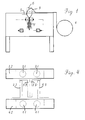
An Hand der Fig. 3 sei beispielhaft die Aufbauform der Werkzeugantriebe und deren Wirkungsweise erörtert. Aus Gründen der Übersicht ist nur die Lagerung und der Bewegungsablauf eines der zwei spiegelbildlich angeordneten Werkzeugpaare dargestellt.3 is an example of the design of the tool drives and their Effectiveness discussed. For the sake of clarity, only the storage and the Movement sequence of one of the two mirror-image arranged tool pairs is shown.
Das Ausführungsbeispiel zeigt zwei ortsfeste, säulenartige Stützen als Träger 31 für das
Gehäuse 32, das die Antriebe für die Bewegung der Werkzeugträger 33 aufnimmt. Für die
vertikale Bewegung der Werkzeugträger 33 ist im Gehäuse 32 ein Antrieb vorgesehen, der
dieses relativ zu den Stützen 31 vertikal bewegt. Für die horizontale Bewegung ist im Gehäuse
32 ein weiterer Antrieb eingesetzt der die Werkzeugträger 33 gegenüber dem Gehäuse
32 im Sinne einer Öffnungs- oder Schliessbewegung der nicht gezeichneten Werkzeuge
steuert. Für die Bewegung der Gehäuse 32 und der Werkzeugträger 33 können beispielhaft
Linearmotoren oder Spindelantriebe bekannter Bauart eingesetzt werden.The embodiment shows two stationary, columnar supports as a
Die Fig. 3a zeigt, wie das Gehäuse 32 nach dem Öffnen der Werkzeugträger 33 mit den
nicht gezeichneten Werkzeugen entsprechend der gewählten Beutellänge zur nächsten
Siegelstelle nach oben zurückgesetzt ist. In dieser Lage wird der Werkzeugträger 33 und
damit das Werkzeugpaar geschlossen. Nach dem Schliessen des Werkzeugpaares (Fig.
3b) wird das Gehäuse 32 unter Mitnahme der durch die Werkzeugpaare eingeklemmten -
nicht gezeichneten - Schlauchfolie, entsprechend der einstellbaren Länge der Schlauchbeutel
- nach unten in die aus Fig. 3c ersichtliche Stellung bewegt. In dieser Endstellung
werden die Werkzeugträger 33 geöffnet und gleichzeitig das Gehäuse 32 nach oben in die
aus Fig. 3a ersichtliche Stellung gefahren.Fig. 3a shows how the
Für den kontinuierlichen Betrieb ist ein zweites Werkzeugpaar erforderlich, das spiegelbildlich zu den aus Fig. 3 ersichtlichen Aufbau anzuordnen ist. Die Werkzeugträger sind einseitig gelagert, so dass die zur Aufnahme der Werkzeugpaare bestimmten Werkzeugträger im freien Raum zwischen den Gehäusen durch gesteuerte Antriebe kollissionsfrei bewegt werden können.A second pair of tools is required for continuous operation to the arrangement shown in Fig. 3 is to be arranged. The tool carriers are mounted on one side, so that the tool carrier intended for receiving the tool pairs Collision-free in the free space between the housings thanks to controlled drives can be moved.
Die Fig. 4 zeigt schematisch die aus Fig. 3 ersichtliche Aufbauform mit den Stützen 31 und
41, sowie den an den Gehäusen 32 und 42 spiegelbildlich angeordneten Werkzeugträgern
33 und 43 in der Aufsicht. Die Werkzeugträger sind einseitig an den Gehäusen 32 bzw. 42
gelagert, so dass die Bewegungen der Werkzeugträger 33,43 und damit auch der Werkzeuge
durch gesteuerte Antriebe an die gewünschten horizontalen und vertikalen Bewegungsabläufe
mit einstellbarer Länge und Geschwindigkeit angepasst werden können.FIG. 4 schematically shows the construction form shown in FIG. 3 with the
Unter Beibehaltung der Vorteile hinsichtlich kurzer Füll- und Taktzeiten, geringen Materiala ifwandes, niedriger Bauweise, geringen Raumbedarfes und schonender Materialbehandlung, sowie der durch die gesteuerten Antriebe leicht einstellbaren Beutellängen, können die einzusetzenden Werkzeuge beliebig gewählt werden. Der Bewegungsablauf ist mit den Werkzeugpaaren bei kontinuierlichem Folienabzug weitgehend frei programmierbar.While maintaining the advantages in terms of short filling and cycle times, low material ifwandes, low construction, low space requirements and gentle material handling, and the bag lengths, which are easily adjustable by the controlled drives the tools to be used can be chosen arbitrarily. The sequence of movements is with the Tool pairs with continuous film removal largely freely programmable.
Claims (4)
Applications Claiming Priority (2)
| Application Number | Priority Date | Filing Date | Title |
|---|---|---|---|
| DE20202487U DE20202487U1 (en) | 2002-02-19 | 2002-02-19 | Device for producing tubular bags |
| DE20202487U | 2002-02-19 |
Publications (2)
| Publication Number | Publication Date |
|---|---|
| EP1340687A2 true EP1340687A2 (en) | 2003-09-03 |
| EP1340687A3 EP1340687A3 (en) | 2005-11-23 |
Family
ID=7967927
Family Applications (1)
| Application Number | Title | Priority Date | Filing Date |
|---|---|---|---|
| EP03003510A Withdrawn EP1340687A3 (en) | 2002-02-19 | 2003-02-15 | Arrangement for manufacturing hose-like bags |
Country Status (2)
| Country | Link |
|---|---|
| EP (1) | EP1340687A3 (en) |
| DE (1) | DE20202487U1 (en) |
Cited By (2)
| Publication number | Priority date | Publication date | Assignee | Title |
|---|---|---|---|---|
| WO2006049722A2 (en) * | 2004-11-02 | 2006-05-11 | Sealed Air Corporation | Apparatus and method for forming inflated containers |
| DE102012021920A1 (en) * | 2012-11-09 | 2014-05-15 | Kiefel Gmbh | Joining installation, method for producing a product by means of a joining installation and product produced therewith |
Families Citing this family (1)
| Publication number | Priority date | Publication date | Assignee | Title |
|---|---|---|---|---|
| CH704455A1 (en) | 2011-02-09 | 2012-08-15 | Ferag Ag | Method and apparatus for packaging products. |
Citations (3)
| Publication number | Priority date | Publication date | Assignee | Title |
|---|---|---|---|---|
| GB1202419A (en) * | 1967-02-10 | 1970-08-19 | Leon Doyen | Machine for packing liquid products |
| US4133162A (en) * | 1976-03-23 | 1979-01-09 | Papeteries De Belgique | Process and means for preforming containers or cartons from a tube which is formed of a material which can be automatically welded by pressure |
| US4729210A (en) * | 1984-02-02 | 1988-03-08 | Padeco S.A. | Process and apparatus for packaging articles in stretchable plastic film |
Family Cites Families (3)
| Publication number | Priority date | Publication date | Assignee | Title |
|---|---|---|---|---|
| DE3545228A1 (en) * | 1985-12-20 | 1987-07-02 | Rovema Gmbh | PACKING MACHINE FOR THE PRODUCTION, FILLING AND SEALING OF BAGS |
| DE19808789B4 (en) * | 1998-03-03 | 2008-02-07 | Rovema - Verpackungsmaschinen Gmbh | Fill and seal machine |
| DE29822122U1 (en) * | 1998-12-11 | 2000-04-20 | Vision Verpackungstechnik Gmbh | Device for processing continuously moving material |
-
2002
- 2002-02-19 DE DE20202487U patent/DE20202487U1/en not_active Expired - Lifetime
-
2003
- 2003-02-15 EP EP03003510A patent/EP1340687A3/en not_active Withdrawn
Patent Citations (3)
| Publication number | Priority date | Publication date | Assignee | Title |
|---|---|---|---|---|
| GB1202419A (en) * | 1967-02-10 | 1970-08-19 | Leon Doyen | Machine for packing liquid products |
| US4133162A (en) * | 1976-03-23 | 1979-01-09 | Papeteries De Belgique | Process and means for preforming containers or cartons from a tube which is formed of a material which can be automatically welded by pressure |
| US4729210A (en) * | 1984-02-02 | 1988-03-08 | Padeco S.A. | Process and apparatus for packaging articles in stretchable plastic film |
Cited By (5)
| Publication number | Priority date | Publication date | Assignee | Title |
|---|---|---|---|---|
| WO2006049722A2 (en) * | 2004-11-02 | 2006-05-11 | Sealed Air Corporation | Apparatus and method for forming inflated containers |
| WO2006049722A3 (en) * | 2004-11-02 | 2006-08-17 | Sealed Air Corp | Apparatus and method for forming inflated containers |
| US8020358B2 (en) | 2004-11-02 | 2011-09-20 | Sealed Air Corporation (Us) | Apparatus and method for forming inflated containers |
| US9340311B2 (en) | 2004-11-02 | 2016-05-17 | Sealed Air Corporation (Us) | Apparatus and method for forming inflated containers |
| DE102012021920A1 (en) * | 2012-11-09 | 2014-05-15 | Kiefel Gmbh | Joining installation, method for producing a product by means of a joining installation and product produced therewith |
Also Published As
| Publication number | Publication date |
|---|---|
| DE20202487U1 (en) | 2003-07-03 |
| EP1340687A3 (en) | 2005-11-23 |
Similar Documents
| Publication | Publication Date | Title |
|---|---|---|
| DE3905605C2 (en) | Method and device for manufacturing, filling and closing bags | |
| DE19745852B4 (en) | Foil bag filling machine and foil bag filling process | |
| DE2415228C2 (en) | Device for manufacturing and filling sacks made of thermally weldable material | |
| CH672767A5 (en) | ||
| DE4313325C2 (en) | Device for filling and closing packages | |
| CH442711A (en) | Method and device for the continuous production of hollow bodies from thermoplastic material | |
| DE4122692B4 (en) | Device for wrapping cuboid objects | |
| CH417449A (en) | Device for packing bulk goods in a protective gas atmosphere | |
| EP0513439A1 (en) | Device for the filling and closing of packages for flowable products | |
| DE1094562B (en) | Method and device for the production of sterile packages by continuously filling plastic tubes with aseptic milk and similar liquid sterile filling goods | |
| EP1340687A2 (en) | Arrangement for manufacturing hose-like bags | |
| DE102004049376B4 (en) | Method for generating a welding force | |
| DE102017120355A1 (en) | FORMATION FOR A DEEP PACKING MACHINE AND METHOD FOR CHANGING A FORM STAMP | |
| EP0624458B1 (en) | Method and apparatus for manufacturing bags out of a plastics film, especially for beverages and foodstuffs | |
| EP1113962B1 (en) | Method and device for opening and filling pre-manufactured bag packages | |
| EP2174872B1 (en) | Transport device for packages, in particular for tobacco pouches | |
| DE3238553C2 (en) | Method for producing a container for bulk material from a plastic tube laid flat and device for carrying out the method | |
| DE102005018545A1 (en) | Method for production and filling of bags used in e.g. foodstuffs industry, involves supplying roll of hose-like material already added with slide fasteners and bag sidewalls to form, fill, and seal (FFS) machine | |
| DE2310787C2 (en) | Method and device for the production of cans with opening threads | |
| DE19624539C2 (en) | Device for the production of cup-shaped lids from a plastic film strip | |
| DE1511627C3 (en) | Apparatus for producing evacuated bag packs | |
| DE1165481B (en) | Method and device for closing bags made of thermally weldable material and filled with liquid or solid material | |
| EP0945372B1 (en) | Device and method for conveying articles | |
| DE102021115738A1 (en) | tubing coating device | |
| EP3858749A1 (en) | Deep drawing packaging machine with vacuum cooling station and method for vacuum cooling hot-packed products |
Legal Events
| Date | Code | Title | Description |
|---|---|---|---|
| PUAI | Public reference made under article 153(3) epc to a published international application that has entered the european phase |
Free format text: ORIGINAL CODE: 0009012 |
|
| AK | Designated contracting states |
Kind code of ref document: A2 Designated state(s): AT BE BG CH CY CZ DE DK EE ES FI FR GB GR HU IE IT LI LU MC NL PT SE SI SK TR |
|
| AX | Request for extension of the european patent |
Extension state: AL LT LV MK RO |
|
| PUAL | Search report despatched |
Free format text: ORIGINAL CODE: 0009013 |
|
| AK | Designated contracting states |
Kind code of ref document: A3 Designated state(s): AT BE BG CH CY CZ DE DK EE ES FI FR GB GR HU IE IT LI LU MC NL PT SE SI SK TR |
|
| AX | Request for extension of the european patent |
Extension state: AL LT LV MK RO |
|
| 17P | Request for examination filed |
Effective date: 20060523 |
|
| AKX | Designation fees paid |
Designated state(s): AT BE BG CH CY CZ DE DK EE ES FI FR GB GR HU IE IT LI LU MC NL PT SE SI SK TR |
|
| 17Q | First examination report despatched |
Effective date: 20060920 |
|
| STAA | Information on the status of an ep patent application or granted ep patent |
Free format text: STATUS: THE APPLICATION IS DEEMED TO BE WITHDRAWN |
|
| 18D | Application deemed to be withdrawn |
Effective date: 20070131 |