EP0908651A2 - Rückschlagventileinrichtung - Google Patents
Rückschlagventileinrichtung Download PDFInfo
- Publication number
- EP0908651A2 EP0908651A2 EP98117761A EP98117761A EP0908651A2 EP 0908651 A2 EP0908651 A2 EP 0908651A2 EP 98117761 A EP98117761 A EP 98117761A EP 98117761 A EP98117761 A EP 98117761A EP 0908651 A2 EP0908651 A2 EP 0908651A2
- Authority
- EP
- European Patent Office
- Prior art keywords
- channel
- valve device
- nozzle
- connecting piece
- molded part
- Prior art date
- Legal status (The legal status is an assumption and is not a legal conclusion. Google has not performed a legal analysis and makes no representation as to the accuracy of the status listed.)
- Granted
Links
Images
Classifications
-
- F—MECHANICAL ENGINEERING; LIGHTING; HEATING; WEAPONS; BLASTING
- F16—ENGINEERING ELEMENTS AND UNITS; GENERAL MEASURES FOR PRODUCING AND MAINTAINING EFFECTIVE FUNCTIONING OF MACHINES OR INSTALLATIONS; THERMAL INSULATION IN GENERAL
- F16K—VALVES; TAPS; COCKS; ACTUATING-FLOATS; DEVICES FOR VENTING OR AERATING
- F16K15/00—Check valves
- F16K15/14—Check valves with flexible valve members
- F16K15/144—Check valves with flexible valve members the closure elements being fixed along all or a part of their periphery
- F16K15/147—Check valves with flexible valve members the closure elements being fixed along all or a part of their periphery the closure elements having specially formed slits or being of an elongated easily collapsible form
-
- B—PERFORMING OPERATIONS; TRANSPORTING
- B60—VEHICLES IN GENERAL
- B60S—SERVICING, CLEANING, REPAIRING, SUPPORTING, LIFTING, OR MANOEUVRING OF VEHICLES, NOT OTHERWISE PROVIDED FOR
- B60S1/00—Cleaning of vehicles
- B60S1/02—Cleaning windscreens, windows or optical devices
- B60S1/46—Cleaning windscreens, windows or optical devices using liquid; Windscreen washers
- B60S1/48—Liquid supply therefor
- B60S1/52—Arrangement of nozzles; Liquid spreading means
-
- Y—GENERAL TAGGING OF NEW TECHNOLOGICAL DEVELOPMENTS; GENERAL TAGGING OF CROSS-SECTIONAL TECHNOLOGIES SPANNING OVER SEVERAL SECTIONS OF THE IPC; TECHNICAL SUBJECTS COVERED BY FORMER USPC CROSS-REFERENCE ART COLLECTIONS [XRACs] AND DIGESTS
- Y10—TECHNICAL SUBJECTS COVERED BY FORMER USPC
- Y10T—TECHNICAL SUBJECTS COVERED BY FORMER US CLASSIFICATION
- Y10T137/00—Fluid handling
- Y10T137/7722—Line condition change responsive valves
- Y10T137/7837—Direct response valves [i.e., check valve type]
- Y10T137/7879—Resilient material valve
- Y10T137/788—Having expansible port
- Y10T137/7882—Having exit lip
Definitions
- the invention relates to a valve device, in particular a window cleaning device in motor vehicles, with the features of the preamble of the claim 1, which is known from practice.
- the device essentially comprises a plastic nozzle housing with a Channel, two nozzles inserted at its end and one plugged into the channel on the other side and a connector, sealed therein, for supplying a cleaning liquid to the nozzles.
- the tubular connector is at its the nozzle end facing with a check valve. This prevents running back the cleaning liquid if the delivery pressure -z. B. by switching off the associated Pump is dismantled.
- the well-known check valve is similar to that of older bicycle tubes known hose valves built.
- the tubular connector is on his closed on the nozzle end, but has at least one in its lateral surface Drilling. This is thin from an outside and pulled onto the connector elastic hose covered. If the pressure inside the connector now rises, so the hose is slightly raised by the liquid emerging from the bore. This then flows between the outer surface of the connector and the inner wall of the hose and exits to the nozzles.
- the invention is based, primarily a generic valve device to improve from a fluidic point of view, but the ease of assembly and maintain a low number of parts.
- the mouth has a flat nozzle-like Cross section and is in between the open end of the connector and the nozzle Axial direction of the channel oriented towards the nozzle. This eliminates redirections Flow so that throttling losses can be minimized.
- the molded part particularly advantageously has an undersize on the connecting piece opened tubular section, of which two pressure-free, the lips forming the mouth go out. These lips can be easily removed from the fluid apart and disrupt the passing beam only a little.
- the elastic molded part is annular at its end facing away from the nozzle circumferential thickening surrounding the connector, it can be as one piece Ring seal between the connector and the housing the necessary Provide sealing of the end section of the channel.
- the channel preferably forms an annular shoulder facing away from the nozzle as a stop for the connector to be inserted. So the fitter has a tangible feedback, that the end position of the connector in the housing is reached. At the same time this ring shoulder in a particularly functional manner as a contact surface for the thickening serve the elastic molded part and thus forms part of the seal of the channel Outside.
- a major advantage in terms of quality assurance is achieved if the Insertion depth of the connector in the channel limiting stop is provided.
- the connector can only be up to a fixed, from the channel side Insert ring shoulder of independent depth into the channel. Accidental crushing of the elastic molded part is thus reliably prevented.
- connection piece is opposite the housing and / or the inner wall of the channel positively by locking means is fixed in its installed position, because separate handles for fixing the connector omitted in the housing and the whole process may also be mechanized can be.
- a channel 2 is recessed in a housing 1, which preferably consists of injection-molded plastic.
- a dash-dotted line pointing obliquely upward to the left denotes the further course of the channel to a nozzle 3, which is only indicated, and a tubular connecting piece 4 is inserted into the end of the channel 2 facing away from the nozzle 3.
- the connecting piece 4 essentially comprises a protruding outwardly from the housing 1, here hose connector 5 running at an angle to channel 2 with an end-side, pulling off a drawn-on hose (not shown here) makes it difficult Thickening and a cylindrical insertion section 6 inserted into the channel 2 one end open to channel 2.
- hose connector 5 running at an angle to channel 2 with an end-side, pulling off a drawn-on hose (not shown here) makes it difficult Thickening and a cylindrical insertion section 6 inserted into the channel 2 one end open to channel 2.
- annular collar 7 protrudes over the outer surface of the connector, whose outer diameter is larger than the diameter of the channel section in which the insertion section 6 is inserted.
- the open end of the insertion section 6 is closable by means of an elastic molded part 8 serving as a check valve.
- the inner wall of the channel 2 forms an annular shoulder 12 at a distance from its opening. This reduces the inside diameter of the channel 2 in steps from one to the outside diameter the insertion section 6 of the connector 4 and the annular thickening 10 of the molded part 8 corresponding dimension approximately to the outer diameter of the tubular section 9 of the molded part 8.
- the annular shoulder 12 forms a mounting end stop for the annular thickening 10, the collar 7 of the connecting piece 4 an accidental squeezing of the elastically deformable thickening 10 safely prevented since it can only approach the outer edge of the housing 1 to this.
- the connector 4 or its insertion section 6 is in the housing 1 or in the inner wall of the channel 2 fixed by means of a locking connection 13, also only indicated.
- Fluid located once in this channel section behind the check valve can only still exit through the nozzle 3.
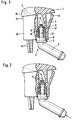
- Fig. 2 only illustrates that the sealing lips of the elastic molded part 8 open when pressure is applied to the connecting piece 4 and release an overflow cross-section through which a fluid jet indicated by arrows, in particular cleaning fluid for a vehicle window or lens, can escape to the nozzle 3 .
- valve device / window cleaning device is made up of a few individual parts Can be preassembled quickly and fail-safe in just a few simple steps.
- the housing 1 is for releasably snapping into a recess of a thin one Body part, e.g. B. a bonnet or an impact absorber of a motor vehicle, intended.
- a head 15 and a recessed head Shaft 16 on the one hand a locking lug 17 and on the other hand an elastic deformable clip hooks 18 are formed.
- the pre-assembled valve device is guided when assembling from the outside into the recess in the sheet until the lower edge of the head 15 projecting in stages relative to the shaft 16 on the Edge of the recess rests.
- the latch 17 and the clip hook 18 pass through the recess come into contact with the underside of the sheet and thus secure the Valve device detachable in the recess.
Abstract
Description
- Fig. 1
- eine Schnittdarstellung durch die Ventileinrichtung in geschlossener Stellung des Rückschlagventils,
- Fig. 2
- die Ventileinrichtung mit durch Fluiddruck geöffnetem Rückschlagventil.
Claims (12)
- Ventileinrichtung, insbesondere Scheibenreinigungseinrichtung in Kraftfahrzeugen, umfassend ein Gehäuse (1) mit einem Kanal (2) und mindestens einer Düse (3) sowie ein rohrförmiges Anschlußstück (4) zum Zuführen eines unter Druck stehenden Fluids, insbesondere einer Reinigungsflüssigkeit, in den Kanal und zur Düse, welches Anschlußstück an seinem düsenseitigen Ende mit einem Rückschlagventil versehen ist, welches gegen eine Rückströmung von der Düse in das Anschlußstück sperrt, dadurch gekennzeichnet, daßdas Anschlußstück (4) an seinem düsenseitigen Ende offen ist unddas Rückschlagventil aus einem elastischen Formteil (8) mit einer normalerweise geschlossenen, durch den Druck der Reinigungsflüssigkeit zu öffnenden Mündung besteht.
- Ventileinrichtung nach Anspruch 1, dadurch gekennzeichnet, daß die Mündung des Formteils (8) einen flachdüsenartigen Querschnitt hat und zwischen dem offenen Ende des Anschlußstücks (4) und der Düse (3) in Achsrichtung des Kanals (2) zu der Düse (3) hin orientiert ist.
- Ventileinrichtung nach Anspruch 1 oder 2, dadurch gekennzeichnet, daß das Formteil (8) einen auf das Anschlußstück (4) mit Untermaß aufgezogenen rohrförmigen Abschnitt (9) aufweist, von dem zwei drucklos aneinanderliegende, die Mündung bildende Dichtlippen (11) ausgehen.
- Ventileinrichtung nach einem der vorstehenden Ansprüche, dadurch gekennzeichnet, daß das elastische Formteil (8) den auf die Mündung folgenden Bereich des Kanals (2) durch Ausfüllen eines zwischen dem Anschlußstück (4) und dem Gehäuse (1) gebildeten Ringspalts abdichtet.
- Ventileinrichtung nach einem der vorstehenden Ansprüche, dadurch gekennzeichnet, daß das elastische Formte (8) an seinem von der Düse (3) abgewandten Ende eine ringförmig umlaufende, das Anschlußstück (4) umgebende Verdickung (10) hat.
- Ventileinrichtung nach einem der vorstehenden Ansprüche, dadurch gekennzeichnet, daß der Kanal (2) eine von der Düse (3) abgewandte Ringschulter (12) als Anschlag für das einzuschiebende Anschlußstück (4) bildet.
- Ventileinrichtung nach den Ansprüchen 5 und 6, dadurch gekennzeichnet, daß die Verdickung (10) des Formteils (8) in Einbaulage des Anschlußstücks (4) gegen die Ringschulter (12) mit Vorspannung in axialer Richtung des Kanals (2) anliegt.
- Ventileinrichtung nach einem der vorstehenden Ansprüche, dadurch gekennzeichnet, daß ein die Einstecktiefe des Anschlußstücks (4) in den Kanal (2) begrenzender Anschlag (Ringbund 7) vorgesehen ist.
- Ventileinrichtung nach Anspruch 8, dadurch gekennzeichnet, daß der Anschlag durch einen außen einstückig an das Anschlußstück (4) angeformten Ringbund (7) gebildet ist, dessen Außendurchmesser größer als der einsteckseitige Durchmesser des Kanals (2) ist.
- Ventileinrichtung nach einem der vorstehenden Ansprüche, dadurch gekennzeichnet, daß der Außendurchmesser des elastischen Formteils (8) im wesentlichen kleiner als der Außendurchmesser eines in den Kanal (2) einzuführenden Einsteckabschnitts (6) des Anschlußstücks (4) ist und daß letzteres an seinem endseitigen Außenrand eine Rille aufweist, auf welche das elastische Formteil (8) aufziehbar ist.
- Ventileinrichtung nach Anspruch 10, dadurch gekennzeichnet, daß der Außendurchmesser der elastischen Verdickung (10) gleich groß wie oder geringfügig größer als der des Einsteckabschnitts (6) ist.
- Ventileinrichtung nach einem der vorstehenden Ansprüche, dadurch gekennzeichnet, daß das Anschlußstück (4) gegenüber dem Gehäuse (1) und/oder der Innenwand des Kanals (2) formschlüssig durch Rastmittel (13) in seiner Einbaulage fixiert ist.
Applications Claiming Priority (2)
| Application Number | Priority Date | Filing Date | Title |
|---|---|---|---|
| DE19744040A DE19744040B4 (de) | 1997-10-06 | 1997-10-06 | Scheibenreinigungseinrichtung |
| DE19744040 | 1997-10-06 |
Publications (3)
| Publication Number | Publication Date |
|---|---|
| EP0908651A2 true EP0908651A2 (de) | 1999-04-14 |
| EP0908651A3 EP0908651A3 (de) | 2000-07-26 |
| EP0908651B1 EP0908651B1 (de) | 2003-04-09 |
Family
ID=7844698
Family Applications (1)
| Application Number | Title | Priority Date | Filing Date |
|---|---|---|---|
| EP98117761A Expired - Lifetime EP0908651B1 (de) | 1997-10-06 | 1998-09-18 | Rückschlagventileinrichtung |
Country Status (4)
| Country | Link |
|---|---|
| US (2) | US6155299A (de) |
| EP (1) | EP0908651B1 (de) |
| DE (2) | DE19744040B4 (de) |
| ES (1) | ES2196447T3 (de) |
Cited By (3)
| Publication number | Priority date | Publication date | Assignee | Title |
|---|---|---|---|---|
| WO2000056583A1 (de) * | 1999-03-23 | 2000-09-28 | Robert Bosch Gmbh | Spritzdüse für eine scheibenwaschanlage |
| WO2001028829A1 (de) * | 1999-10-21 | 2001-04-26 | Robert Bosch Gmbh | Düsenanordnung zur zuführung einer flüssigkeit auf ein ziel, zum beispiel eine scheibe eines fahrzeugs |
| CN107042215A (zh) * | 2016-02-05 | 2017-08-15 | 法雷奥系统公司 | 用于机动车辆的光学检测系统以及用于清洁该系统的装置 |
Families Citing this family (13)
| Publication number | Priority date | Publication date | Assignee | Title |
|---|---|---|---|---|
| DE19833142A1 (de) * | 1998-07-23 | 2000-02-03 | Mannesmann Vdo Ag | Scheibenreinigungsanlage |
| JP3768116B2 (ja) * | 2001-05-11 | 2006-04-19 | アスモ株式会社 | ウインドウ・ウォッシャノズル及びノズル成形用金型装置 |
| DE10236965A1 (de) * | 2002-08-13 | 2004-03-04 | Volaplast Werner Hoppach Kg | Rückschlagventil zur Verwendung in einer Scheiben- oder Scheinwerferwaschanlage eines Fahrzeugs |
| DE10242034B4 (de) * | 2002-09-11 | 2014-04-30 | Continental Automotive Gmbh | Teileinheit für eine Scheibenwaschanlage |
| DE10253850A1 (de) * | 2002-11-15 | 2004-05-27 | Hansgrohe Ag | Abgabesystem für Wasser |
| GB2401778B (en) * | 2003-05-21 | 2006-09-06 | Rehau Ag & Co | Nozzle body for a cleaning system on a motor vehicle |
| JP4295587B2 (ja) * | 2003-09-17 | 2009-07-15 | 本田技研工業株式会社 | 空気吸入パイプの端末構造 |
| DE102005018449A1 (de) * | 2005-04-20 | 2006-10-26 | Roediger Vakuum- Und Haustechnik Gmbh | Unterdruckventil |
| FR2976538B1 (fr) * | 2011-06-17 | 2013-07-26 | Valeo Systemes Dessuyage | Support de connecteurs et dispositif de distribution de liquide lave-glace pour balais d'essuie-glace de vehicule automobile |
| FR3003219B1 (fr) * | 2013-03-14 | 2016-11-18 | Valeo Systemes Dessuyage | Dispositif de distribution de liquide lave-glace de balais d'essuie-glace de vehicule automobile |
| DE102013211870B4 (de) | 2013-06-21 | 2022-03-24 | Continental Automotive Gmbh | Waschdüse für eine Scheibenwaschanlage eines Kraftfahrzeuges |
| FR3013291B1 (fr) * | 2013-11-21 | 2017-07-14 | Valeo Systemes Dessuyage | Interface hydraulique chauffante pour un systeme d'approvisionnement et/ou de distribution en liquide lave glace de vehicule automobile |
| JP6259163B2 (ja) * | 2015-02-17 | 2018-01-10 | コーニンクレッカ フィリップス エヌ ヴェKoninklijke Philips N.V. | スチーマ及び衣服用スチーマ |
Family Cites Families (17)
| Publication number | Priority date | Publication date | Assignee | Title |
|---|---|---|---|---|
| US2616581A (en) * | 1945-10-08 | 1952-11-04 | Seamless Rubber Co | Nursing outfit |
| US2598601A (en) * | 1947-02-05 | 1952-05-27 | Trico Products Corp | Windshield clearing system |
| GB924557A (en) * | 1958-06-09 | 1963-04-24 | Denis James Battersby | Improvements relating to washers for vehicle windscreens |
| US3199787A (en) * | 1963-08-26 | 1965-08-10 | Trico Products Corp | Windshield washer system |
| SE313956B (de) * | 1965-08-02 | 1969-08-25 | Mitsubishi Heavy Ind Ltd | |
| FR1545811A (fr) * | 1967-10-02 | 1968-11-15 | Dba Sa | Commande de lave-glace |
| US4084606A (en) * | 1974-04-23 | 1978-04-18 | Baxter Travenol Laboratories, Inc. | Fluid transfer device |
| US4426062A (en) * | 1982-02-10 | 1984-01-17 | Black & Decker Inc. | Fluid flow control valves |
| DE3433091A1 (de) * | 1984-09-08 | 1986-03-20 | Audi AG, 8070 Ingolstadt | Spritzduesenkopf |
| US4725266A (en) * | 1985-03-25 | 1988-02-16 | Siposs George G | Left ventricle vacuum control and pressure relief valve |
| JPS63146264U (de) * | 1987-03-18 | 1988-09-27 | ||
| DE3831380C2 (de) * | 1987-09-26 | 1998-06-04 | Volkswagen Ag | Membranventil für die Doppelförderpumpe von Scheibenwascheinrichtungen in Fahrzeugen |
| JP2536331Y2 (ja) * | 1989-12-28 | 1997-05-21 | 自動車電機工業株式会社 | ウオッシャノズル |
| DE4143316C2 (de) * | 1991-02-21 | 1995-06-29 | Bosch Gmbh Robert | Waschvorrichtung für Abdeckscheiben von Kraftfahrzeugleuchten |
| US5636794A (en) * | 1995-04-12 | 1997-06-10 | Bowles Fluidics Corporation | In-line check valve |
| DE19514825A1 (de) * | 1995-04-21 | 1996-10-24 | Teves Gmbh Alfred | Waschdüse für eine Scheibenwaschanlage eines Fahrzeuges |
| FR2783225B1 (fr) * | 1998-09-10 | 2001-02-23 | Journee Paul Sa | Dispositif perfectionne de projection de liquide de lavage et essuie-glace portant un tel dispositif |
-
1997
- 1997-10-06 DE DE19744040A patent/DE19744040B4/de not_active Expired - Fee Related
-
1998
- 1998-09-18 ES ES98117761T patent/ES2196447T3/es not_active Expired - Lifetime
- 1998-09-18 EP EP98117761A patent/EP0908651B1/de not_active Expired - Lifetime
- 1998-09-18 DE DE59807828T patent/DE59807828D1/de not_active Expired - Fee Related
- 1998-09-24 US US09/162,468 patent/US6155299A/en not_active Expired - Fee Related
-
2000
- 2000-09-20 US US09/665,739 patent/US6260771B1/en not_active Expired - Fee Related
Non-Patent Citations (1)
| Title |
|---|
| None |
Cited By (4)
| Publication number | Priority date | Publication date | Assignee | Title |
|---|---|---|---|---|
| WO2000056583A1 (de) * | 1999-03-23 | 2000-09-28 | Robert Bosch Gmbh | Spritzdüse für eine scheibenwaschanlage |
| US6460780B1 (en) | 1999-03-23 | 2002-10-08 | Robert Bosch Gmbh | Spray nozzle for a windscreen washing system |
| WO2001028829A1 (de) * | 1999-10-21 | 2001-04-26 | Robert Bosch Gmbh | Düsenanordnung zur zuführung einer flüssigkeit auf ein ziel, zum beispiel eine scheibe eines fahrzeugs |
| CN107042215A (zh) * | 2016-02-05 | 2017-08-15 | 法雷奥系统公司 | 用于机动车辆的光学检测系统以及用于清洁该系统的装置 |
Also Published As
| Publication number | Publication date |
|---|---|
| DE19744040B4 (de) | 2004-07-22 |
| EP0908651B1 (de) | 2003-04-09 |
| ES2196447T3 (es) | 2003-12-16 |
| US6155299A (en) | 2000-12-05 |
| US6260771B1 (en) | 2001-07-17 |
| EP0908651A3 (de) | 2000-07-26 |
| DE59807828D1 (de) | 2003-05-15 |
| DE19744040A1 (de) | 1999-04-29 |
Similar Documents
| Publication | Publication Date | Title |
|---|---|---|
| DE102007039106B4 (de) | Farbbehälter für eine Spritzpistole, mit einem Anschlussteil zur Verbindung des Farbbehälters an eine Spritzpistole und Farbspritzeinrichtung | |
| EP0908651B1 (de) | Rückschlagventileinrichtung | |
| EP2027931B1 (de) | Anschlussteil zur Verbindung einer Materialzuführungseinrichtung an eine Spritzpistole | |
| EP1934405B1 (de) | Sanitäres einbauteil | |
| DE102007027282B3 (de) | Kunststoffverdichtergehäuse und Verfahren zur Herstellung eines Kunststoffverdichtergehäuses | |
| DE602004001332T2 (de) | Verbindervorrichtung mit dichtungsschutz | |
| DE102006043879B4 (de) | Vorrichtung zum absperren und steuern des wasserauslasses auseinem sprenger sowie betätigungsanordnung hierfür | |
| DE102006043883A1 (de) | Wasserabsperr- und Auslasssteuervorrichtung für Sprenger | |
| EP3717312B1 (de) | Wischarmsprühvorrichtung | |
| EP0916540A2 (de) | Kraftstoffördereinheit mit einem Leitungsanschluss | |
| EP0755341A1 (de) | Wischarm, insbesondere für kraftfahrzeuge | |
| EP0787864A1 (de) | Sanitäre Sicherungseinrichtung | |
| DE10257783B3 (de) | Düsenanordnung für ein Hochdruckreinigungsgerät | |
| DE202007003299U1 (de) | Zu- und Überlaufgarnitur für Badewannen | |
| DE102008051584A1 (de) | Waschanlage für Fahrzeugscheiben sowie Rückschlagventil für eine solche Anlage | |
| DE3206965C2 (de) | ||
| WO1990010563A1 (de) | Scheibenreinigungsanlage | |
| EP3204669B1 (de) | Ablaufstutzen | |
| DE202010003996U1 (de) | Strahlregler o.dgl. sanitäres Auslaufelement sowie Spritzgusswerkzeug zu dessen Herstellung | |
| DE19756090A1 (de) | Spender für Medien | |
| EP2489799B1 (de) | Abwasserhebeanlage | |
| EP2134994B1 (de) | Vorrichtung zum sperren eines fluiddurchtritts durch ein rohrförmiges teil mittels eines rückschlagventils, insbesondere in einem hausgerät | |
| DE102004025163B4 (de) | Abschirmungselement als Spritzschutz für Verbindungsstellen von unter Druck stehenden, Kraftstoff oder Schmierstoff führenden Rohrleitungen | |
| DE102007044659A1 (de) | Zweiteiliges Ventilgehäuse eines Tiertränkeventils | |
| DE19823573B4 (de) | Kraftstoffördereinheit zum Einsatz in Kraftstofftanks |
Legal Events
| Date | Code | Title | Description |
|---|---|---|---|
| PUAI | Public reference made under article 153(3) epc to a published international application that has entered the european phase |
Free format text: ORIGINAL CODE: 0009012 |
|
| AK | Designated contracting states |
Kind code of ref document: A2 Designated state(s): DE ES FR GB SE |
|
| AX | Request for extension of the european patent |
Free format text: AL;LT;LV;MK;RO;SI |
|
| PUAL | Search report despatched |
Free format text: ORIGINAL CODE: 0009013 |
|
| AK | Designated contracting states |
Kind code of ref document: A3 Designated state(s): AT BE CH CY DE DK ES FI FR GB GR IE IT LI LU MC NL PT SE |
|
| AX | Request for extension of the european patent |
Free format text: AL;LT;LV;MK;RO;SI |
|
| 17P | Request for examination filed |
Effective date: 20000616 |
|
| AKX | Designation fees paid |
Free format text: DE ES FR GB SE |
|
| RAP1 | Party data changed (applicant data changed or rights of an application transferred) |
Owner name: SIEMENS AKTIENGESELLSCHAFT |
|
| 17Q | First examination report despatched |
Effective date: 20020213 |
|
| GRAH | Despatch of communication of intention to grant a patent |
Free format text: ORIGINAL CODE: EPIDOS IGRA |
|
| GRAH | Despatch of communication of intention to grant a patent |
Free format text: ORIGINAL CODE: EPIDOS IGRA |
|
| GRAA | (expected) grant |
Free format text: ORIGINAL CODE: 0009210 |
|
| AK | Designated contracting states |
Designated state(s): DE ES FR GB SE |
|
| REG | Reference to a national code |
Ref country code: GB Ref legal event code: FG4D Free format text: NOT ENGLISH |
|
| REG | Reference to a national code |
Ref country code: SE Ref legal event code: TRGR |
|
| GBT | Gb: translation of ep patent filed (gb section 77(6)(a)/1977) | ||
| PGFP | Annual fee paid to national office [announced via postgrant information from national office to epo] |
Ref country code: SE Payment date: 20030904 Year of fee payment: 6 Ref country code: GB Payment date: 20030904 Year of fee payment: 6 |
|
| PGFP | Annual fee paid to national office [announced via postgrant information from national office to epo] |
Ref country code: ES Payment date: 20030912 Year of fee payment: 6 |
|
| PGFP | Annual fee paid to national office [announced via postgrant information from national office to epo] |
Ref country code: FR Payment date: 20030930 Year of fee payment: 6 |
|
| REG | Reference to a national code |
Ref country code: ES Ref legal event code: FG2A Ref document number: 2196447 Country of ref document: ES Kind code of ref document: T3 |
|
| ET | Fr: translation filed | ||
| PLBE | No opposition filed within time limit |
Free format text: ORIGINAL CODE: 0009261 |
|
| STAA | Information on the status of an ep patent application or granted ep patent |
Free format text: STATUS: NO OPPOSITION FILED WITHIN TIME LIMIT |
|
| 26N | No opposition filed |
Effective date: 20040112 |
|
| PG25 | Lapsed in a contracting state [announced via postgrant information from national office to epo] |
Ref country code: GB Free format text: LAPSE BECAUSE OF NON-PAYMENT OF DUE FEES Effective date: 20040918 |
|
| PG25 | Lapsed in a contracting state [announced via postgrant information from national office to epo] |
Ref country code: SE Free format text: LAPSE BECAUSE OF NON-PAYMENT OF DUE FEES Effective date: 20040919 |
|
| PG25 | Lapsed in a contracting state [announced via postgrant information from national office to epo] |
Ref country code: ES Free format text: LAPSE BECAUSE OF NON-PAYMENT OF DUE FEES Effective date: 20040920 |
|
| EUG | Se: european patent has lapsed | ||
| GBPC | Gb: european patent ceased through non-payment of renewal fee |
Effective date: 20040918 |
|
| PG25 | Lapsed in a contracting state [announced via postgrant information from national office to epo] |
Ref country code: FR Free format text: LAPSE BECAUSE OF NON-PAYMENT OF DUE FEES Effective date: 20050531 |
|
| REG | Reference to a national code |
Ref country code: FR Ref legal event code: ST |
|
| REG | Reference to a national code |
Ref country code: ES Ref legal event code: FD2A Effective date: 20040920 |
|
| PGFP | Annual fee paid to national office [announced via postgrant information from national office to epo] |
Ref country code: DE Payment date: 20061120 Year of fee payment: 9 |
|
| PG25 | Lapsed in a contracting state [announced via postgrant information from national office to epo] |
Ref country code: DE Free format text: LAPSE BECAUSE OF NON-PAYMENT OF DUE FEES Effective date: 20080401 |