EP0908604A1 - Variable Ventilsteuervorrichtung - Google Patents
Variable Ventilsteuervorrichtung Download PDFInfo
- Publication number
- EP0908604A1 EP0908604A1 EP98118846A EP98118846A EP0908604A1 EP 0908604 A1 EP0908604 A1 EP 0908604A1 EP 98118846 A EP98118846 A EP 98118846A EP 98118846 A EP98118846 A EP 98118846A EP 0908604 A1 EP0908604 A1 EP 0908604A1
- Authority
- EP
- European Patent Office
- Prior art keywords
- rocker arm
- valve
- operating mechanism
- set forth
- valve operating
- Prior art date
- Legal status (The legal status is an assumption and is not a legal conclusion. Google has not performed a legal analysis and makes no representation as to the accuracy of the status listed.)
- Granted
Links
Images


Classifications
-
- F—MECHANICAL ENGINEERING; LIGHTING; HEATING; WEAPONS; BLASTING
- F01—MACHINES OR ENGINES IN GENERAL; ENGINE PLANTS IN GENERAL; STEAM ENGINES
- F01L—CYCLICALLY OPERATING VALVES FOR MACHINES OR ENGINES
- F01L13/00—Modifications of valve-gear to facilitate reversing, braking, starting, changing compression ratio, or other specific operations
- F01L13/0015—Modifications of valve-gear to facilitate reversing, braking, starting, changing compression ratio, or other specific operations for optimising engine performances by modifying valve lift according to various working parameters, e.g. rotational speed, load, torque
- F01L13/0036—Modifications of valve-gear to facilitate reversing, braking, starting, changing compression ratio, or other specific operations for optimising engine performances by modifying valve lift according to various working parameters, e.g. rotational speed, load, torque the valves being driven by two or more cams with different shape, size or timing or a single cam profiled in axial and radial direction
-
- F—MECHANICAL ENGINEERING; LIGHTING; HEATING; WEAPONS; BLASTING
- F01—MACHINES OR ENGINES IN GENERAL; ENGINE PLANTS IN GENERAL; STEAM ENGINES
- F01L—CYCLICALLY OPERATING VALVES FOR MACHINES OR ENGINES
- F01L1/00—Valve-gear or valve arrangements, e.g. lift-valve gear
- F01L1/26—Valve-gear or valve arrangements, e.g. lift-valve gear characterised by the provision of two or more valves operated simultaneously by same transmitting-gear; peculiar to machines or engines with more than two lift-valves per cylinder
- F01L1/267—Valve-gear or valve arrangements, e.g. lift-valve gear characterised by the provision of two or more valves operated simultaneously by same transmitting-gear; peculiar to machines or engines with more than two lift-valves per cylinder with means for varying the timing or the lift of the valves
Definitions
- This invention relates to an engine valve actuating system and more particularly to an improved arrangement for achieving variable valve actuation (timing and/or lift) in the operation of an engine valve.
- the invention relates to an improved lash adjustment arrangement useable in engine valve actuation.
- variable valve timing and variable valve lift have been proposed for achieving either or both of the variable valve timing and variable valve lift. For the most part, however, they are fairly complex and add significantly to the complexity of the valve train.
- valve operating mechanism comprised of a single cam shaft having a pair of adjacent cams.
- a pair of adjacent, pivotally supported rocker arms each cooperated with a respective one of the cams.
- a first of the rocker arms had an operating portion for direct cooperation with the valve stem for operating the valve.
- Means provided a selective coupling of the second rocker arm to the first rocker arm for effecting actuation of the valve through the first rocker arm.
- This invention is adapted to be embodied in the valve actuating mechanism for operating a single poppet valve of an engine through cooperation with the stem thereof.
- the valve operating mechanism is comprised of a single cam shaft having a pair of adjacent cams.
- a pair of adjacent, pivotally supported rocker arms each cooperate with a respective one of the cams.
- a first of the rocker arms has an operating portion for direct cooperation with the valve stem for operating the valve.
- Means provide a selective, adjustable coupling of the second rocker arm to the first rocker arm for effecting actuation of the valve through the first rocker arm.
- This coupling includes a replaceable adjusting shim.
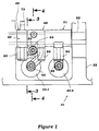
- a portion of a cylinder head assembly of an internal combustion engine is illustrated and is identified generally by the reference numeral 31. Only a portion of the engine is illustrated and specifically the cylinder head thereof because the invention deals, as aforenoted, with a valve actuating mechanism for engines. Therefore, when any details of the construction of the engine are not illustrated, they may be considered to be conventional. Those skilled in the art will be able to determine from the following description how the invention can be utilized with a wide variety of engines.
- the depicted engine and cylinder head 31 are of the four valve cylinder type. This is because the invention has particular utility with multi-valve engines, for reasons which will become apparent. However, the invention can be utilized with engines having any number of valves including only two valves per cylinder or more than two valves in any number.
- the cylinder head assembly 31 includes a main cylinder head member 32 which has an upper surface which carries a bearing and cam carrier 33 and which is closed by a cam cover 34.
- each cylinder of the engine is served by a pair of intake passages 35 that terminate in valve seats 36 which are valved by poppet-type intake valves, indicated generally by the reference numeral 37.
- These valves 37 have head portions 38 that cooperate with the valve seats 36 and stem portions 39 that are slidably supported in valve guides 41 affixed to the cylinder head member 32.
- keeper retainer assemblies 42 retain spring assemblies 43 that act between the keeper retainer assemblies 42 and the cylinder head for biasing the valves 37 to their closed positions, as is well-known in this art.
- a cam shaft is journaled in the cam carrier 43 by bearing surfaces formed by it and bearing caps which are not illustrated.
- the cam shaft 44 has three lobes comprised of a first, center lobe 45, a second lobe 46, and a third lobe 47.
- first, second and third rocker arms are associated with these lobes 45-47.
- rocker arms 48, 49 and 51 are all journaled on a common rocker arm shaft 52 that is carried by the cam carrier member 33 in any known manner.
- cam lobes 45 and 46 and their cooperating rocker arms 48 and 49 are associated with one of the valves 37, the keeper retainer of which is indicated by the reference numeral 42-1.
- the remaining cam lobe 47 and rocker arm 51 are associated with and operate the remaining intake valve 37 and their association is indicated by the reference numeral 42-2, which identifies the keeper retainer of this remaining valve.
- the first rocker arm 48 is a rocker arm which, under all conditions, operates the associated intake valve having a retainer 42-1.
- This rocker arm 48 has a follower portion 59 which is engaged with the cam lobe 45 and which is actuated by it.
- An actuating portion 61 extends integrally outwardly from the area adjacent the cam follower 59 and carries an adjusting screw 62 at its outer end which cooperates with the tip of the stem 39 of the associated valve.
- this rocker arm generally operates as a conventional rocker arm for the valve actuation during such time as the second rocker arm 49 is not coupled to it. This coupling method will be described later.
- the rocker arm 49 has an outwardly extending arm which forms an integral follower 63 that is engaged by the cam lobe 46.
- the cam lobe 46 is of a larger lift and larger diameter than that of the cam lobe 45. This is readily apparent from Figure 10.
- this cam lobe 46 may also be configured to provide slightly different timing through its cooperation with the first rocker arm 48.
- the rocker arm 49 Adjacent the follower surface 63, the rocker arm 49 is provided with a protrusion 64 that receives an adjusting screw 65.
- This adjusting screw 65 operates in conjunction with a coupling mechanism to, at times, control the operation of the first rocker arm 48. That mechanism will be described very shortly.
- a biasing arrangement shown in Figure 3 is provided.
- a spring carrier 66 is fixed to the cam carrier 33 in a known manner.
- the spring carrier 66 is provided with a plurality of pockets, one for each rocker arm 49.
- a spring arrangement, indicated by the reference numeral 67, is supported in each of these pockets.
- the spring arrangement includes an outer cylinder member 68 which defines a bore in which a sliding biasing member 69 is provided.
- the sliding biasing member 69 is biased by a coil compression spring 71 into engagement with a further follower surface 72 formed on a portion of the rocker arm 49 that extends in somewhat diametrical opposition to the portion that forms the follower surface 63.
- the spring 71 acting through the biasing member 69 and rocker arm surface 72 will maintain the rocker arm follower 63 in engagement with the cam lobe 46.
- FIGs 4 through 7 show this coupling mechanism, which is indicated generally by the reference numeral 73, in the disengaged condition so that the first rocker arm 48 operates without any control or interference from the second rocker arm 43. Under this condition, the cam lobe 45 and first rocker arm 48 control the degree of maximum opening and timing of opening of the valve 37 with the fully-opened position being shown in Figure 5.
- the rocker arm 48 has a boss portion 74 that is formed adjacent its follower surface 59 but below it.
- a cylindrical bore 75 is formed in this boss 74.
- a coupling plunger member having a configuration shown in Figures 4-10 and indicated generally by the reference numeral 76, is slidably supported within this bore.
- This coupling plunger member 76 has a head or top portion 77 which is positioned to be and is engaged during the running of the engine by the screw 65.
- the lower end of the bore 74 is partially closed by a cap 78 which forms an engagement for a biasing spring 79 that acts on the lower end of the coupling plunger member 76.
- This spring 79 keeps the coupling plunger member 76 and specifically its surface 77 in consant engagement with the adjusting screw 65. It should be apparent, however, that if desired, some clearance may be maintained in this gap depending upon how the valve operation is to be accomplished. Also in some views the position of the plunger member 76 in the bore may not be the true position depending upon the lift characteristics of the respective cams 45 and 46 and specifically that of their lobes.
- the coupling plunger member 76 is formed with a bore 81 that extends from a flat surface 82 formed in a side thereof by a machined recess 83. Received within the bore 81 is a return spring arrangement that is comprised of a pair of end caps 85 and 86 that are urged apart by a coil compression spring 87.
- this compression spring 87 causes the retaining member 83 to be urged to a position where a flat surface of it is coextensive with the surface 82. Under this condition the surface 82 is engaged by a slidable locking member 88.
- the locking member 88 is slidably supported within a bore 89 that extends through the rocker arm 48 below its journal on the rocker arm shaft 51. The outer end of this bore 89 is closed by a closure plug 91 and in the uncoupled state, the locking member 88 is abuttingly engaged with this closure plug 91.
- a gap 92 is provided between it and the end closure 91.
- This gap communicates with an oil control passage 93 that extends through the rocker arm shaft 51 and rocker arm 48.
- the rocker arm shaft 51 is hollow and hydraulic fluid pressure may be exerted selectively through this passage 73 to the area 92 in accordance with a desired control strategy.
- One such strategy will be described later by reference to the embodiment of Figure 11.
- rocker arm 51 and cam lobe 47 that operate the remaining intake valve which does not have its lift varied in this embodiment.
- the rocker arm 51 has a follower surface 94 that is engaged by the cam lobe 47.
- An adjusting screw 95 carried at the tip of this rocker arm cooperates with the stem of this valve to operate it in a normal manner.
- Varying types of lift arrangements may be employed and different lift ratios and/or valve timing between the non-variable actuated valve and the variable actuated valve. That is the lift and/or timing of the valve operated by the cam 47 may be the same as that provided by either of the cams 45 or 46 associated with the other valve or different from either of them.
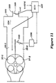
- FIG 11 is a view that shows one way in which this mechanism may operate.
- This view shows the induction system schematically and it now will be described by reference to that Figure.
- the normally or non-variably actuated valve is indicated by the reference numeral 37-2, while the variably actuated valve is indicated by the reference numeral 37-1.
- the intake passages 35 associated therewith have also been indicated by the same suffixes, i.e., 35-2 and 35-1.
- an air inlet device draws atmospheric air through an inlet opening 102 in which a manually actuated throttle control valve 103 is positioned.
- the air inlet device 101 forms a plenum chamber 104 that communicates with the runners 35-1 and 35-2 of each cylinder.
- a control valve 105 is provided in the runner 35-2 and is operated by a servo motor 106 under the control of an ECU, indicated generally by the reference numeral 107.
- the intake valve 37-1 and its operation is adjusted to optimize primarily the low and mid-range performance of the engine.
- the cam lobe 45 and rocker arm 48 can be tailored for optimum performance under low-speed and low-mid range running.
- the cam lobe 46 and rocker arm 49 are coupled for a higher range of operation and may provide a substantially greater lift so as to improve the performance under higher speeds and loads.
- control strategy for the ECU is to sense throttle position or load and engine speed and be mapped so as to activate the servo motor 106 and maintain the throttle valve 105 in a closed position during low-speed and low-to-medium mid-range running.
- the ECU effects opening of the control valve 105 by the servo motor 106.
- the engine can provide very good performance under a wide variety of speeds and loads due to the use of the variable valve actuating mechanism and the control valve 105.
- valves 37-1 and 37-2 can be either the same or different depending upon the particular engine and taning arrangement selected, as already noted.
- Figures 12 and 20 show another embodiment of the invention wherein both of the intake valves 37-1 and 37-2 are provided with a variable valve actuating mechanism.
- the cam shaft is provided with, in addition to, the lobes 45 and 46, for actuating the first intake valve 37-1, with additional lobes 151 and 152 for operating the rocker arms 48 and 49 associated with the remaining valve 37-2.
- rocker arms 48 and 49 associated with the second intake valve 37-2 are mirror images so as to permit the two rocker arms 48 to be positioned next to each other and the other two rocker arms to be spaced more widely. With this type of arrangement, as shown, the initial lift for the valve 37-2 is less than that of the valve 37-1 but the maximum lift provided by the cam lobes 46 and 152 can be the same.
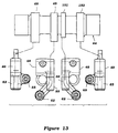
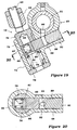
- Figures 21 - 23 show yet another embodiment.
- the rocker arms are reversed from the position utilized in Figures 12 through 21. That is, the direct actuating rocker arms 48 are disposed outwardly of the indirect acting rocker arms 49.
- varying lift arrangements may be employed.
- the initial lift of the valve 37-1 is substantially greater than that of the remaining valve 37-2 while the maximum lift also is larger but only slightly larger as indicated by the respective cam lobe portions.
- Figure 23 also shows a different biasing arrangement for the second rocker arms that is like that used in the embodiment of Figure 15. Since these are the only main differences from former embodiments, components which are the same or substantially the same have been identified by the same reference numerals.
- the second rocker arms 48 have, on the opposite side from their follower surfaces 59, a protruding portion 251 that is engaged by a spring return mechanism which is in essence the same as that employed in and shown in detail in Figure 3.
- this return mechanism 67 is mounted directly in the cylinder head member 32 rather than on the cam carrier 33. In all other regards, this embodiment is the same and thus, further description of it is not believed to be necessary to permit those skilled in the art to practice the invention.
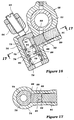
- Figures 24 and 25 show an embodiment which is generally the same as the embodiment of Figures 12-20 but also permits the use of the biasing arrangement as seen in Figures 15 and 23.
- This embodiment differs from that earlier embodiment only in the way in which the two rocker arms 48 and 49 cooperate with each other so as to avoid the necessity of utilizing the adjusting screws 65. As may be seen in Figure 24, this permits the bearing area 63 of the second rocker arms to be substantially wider. Also the cam lobes 46 and 152 may be so widened. Thus, wear can be reduced and also the entire cylinder head construction can be made more compact.
- the portion of the rocker arm 63 which previously carried the adjusting screw 65 merely overlie an adjusting pad 201 ( Figure 25) that is received in a complimentary recess formed in the upper portion of the plunger assembly 73 and specifically the member 76 thereof.
- the height or thickness of this shim 201 an be varied so as to provide the desired clearance and avoid the use of an adjusting screw.
- this arrangement provides a larger wear area between the two rocker arms 49 and 48 and thus also reduces wear. In all other regards, this construction is the same as that previously described.
Landscapes
- Engineering & Computer Science (AREA)
- Mechanical Engineering (AREA)
- General Engineering & Computer Science (AREA)
- Valve Device For Special Equipments (AREA)
- Valve-Gear Or Valve Arrangements (AREA)
Applications Claiming Priority (3)
| Application Number | Priority Date | Filing Date | Title |
|---|---|---|---|
| JP27416197A JP4014702B2 (ja) | 1996-10-07 | 1997-10-07 | 内燃エンジンの動弁機構 |
| JP27416197 | 1997-10-07 | ||
| JP274161/97 | 1997-10-07 |
Publications (2)
| Publication Number | Publication Date |
|---|---|
| EP0908604A1 true EP0908604A1 (de) | 1999-04-14 |
| EP0908604B1 EP0908604B1 (de) | 2002-05-15 |
Family
ID=17537894
Family Applications (1)
| Application Number | Title | Priority Date | Filing Date |
|---|---|---|---|
| EP19980118846 Expired - Lifetime EP0908604B1 (de) | 1997-10-07 | 1998-10-06 | Variable Ventilsteuervorrichtung |
Country Status (2)
| Country | Link |
|---|---|
| EP (1) | EP0908604B1 (de) |
| DE (1) | DE69805382T2 (de) |
Cited By (1)
| Publication number | Priority date | Publication date | Assignee | Title |
|---|---|---|---|---|
| DE10323427B4 (de) * | 2002-05-24 | 2008-04-10 | Mitsubishi Jidosha Kogyo K.K. | Ventilsystem für Verbrennungsmotoren |
Citations (4)
| Publication number | Priority date | Publication date | Assignee | Title |
|---|---|---|---|---|
| DE3613945A1 (de) * | 1985-04-26 | 1986-10-30 | Mazda Motor Corp., Hiroshima | Veraenderbarer ventilmechanismus fuer verbrennungsmaschinen |
| EP0452671A2 (de) * | 1990-03-14 | 1991-10-23 | Suzuki Kabushiki Kaisha | Ventiltriebvorrichtung für Viertaktbrennkraftmaschine |
| EP0583584A1 (de) * | 1992-07-16 | 1994-02-23 | Mitsubishi Jidosha Kogyo Kabushiki Kaisha | Ventilsteuerungsvorrichtung mit Mechanismus zur Veränderung der Ventilsteuerzeit |
| EP0834647A1 (de) | 1996-10-07 | 1998-04-08 | Yamaha Hatsudoki Kabushiki Kaisha | Ventiltriebvorrichtung für Brennkraftmaschine |
-
1998
- 1998-10-06 DE DE1998605382 patent/DE69805382T2/de not_active Expired - Lifetime
- 1998-10-06 EP EP19980118846 patent/EP0908604B1/de not_active Expired - Lifetime
Patent Citations (4)
| Publication number | Priority date | Publication date | Assignee | Title |
|---|---|---|---|---|
| DE3613945A1 (de) * | 1985-04-26 | 1986-10-30 | Mazda Motor Corp., Hiroshima | Veraenderbarer ventilmechanismus fuer verbrennungsmaschinen |
| EP0452671A2 (de) * | 1990-03-14 | 1991-10-23 | Suzuki Kabushiki Kaisha | Ventiltriebvorrichtung für Viertaktbrennkraftmaschine |
| EP0583584A1 (de) * | 1992-07-16 | 1994-02-23 | Mitsubishi Jidosha Kogyo Kabushiki Kaisha | Ventilsteuerungsvorrichtung mit Mechanismus zur Veränderung der Ventilsteuerzeit |
| EP0834647A1 (de) | 1996-10-07 | 1998-04-08 | Yamaha Hatsudoki Kabushiki Kaisha | Ventiltriebvorrichtung für Brennkraftmaschine |
Cited By (1)
| Publication number | Priority date | Publication date | Assignee | Title |
|---|---|---|---|---|
| DE10323427B4 (de) * | 2002-05-24 | 2008-04-10 | Mitsubishi Jidosha Kogyo K.K. | Ventilsystem für Verbrennungsmotoren |
Also Published As
| Publication number | Publication date |
|---|---|
| DE69805382T2 (de) | 2002-11-07 |
| EP0908604B1 (de) | 2002-05-15 |
| DE69805382D1 (de) | 2002-06-20 |
Similar Documents
| Publication | Publication Date | Title |
|---|---|---|
| CA1274132A (en) | Valve operating mechanism for internal combustion engine | |
| US6354254B1 (en) | Exhaust and intake rocker arm assemblies for modifying valve lift and timing during positive power | |
| US5046462A (en) | Rocker arm arrangement for variable valve timing type internal combustion engine valve train | |
| EP0608925B1 (de) | Kompakte Ventilstössel | |
| EP0420159B1 (de) | Kipphebelanordnung für verstellbaren Ventilantrieb in einer Brennkraftmaschine | |
| EP0213758A1 (de) | Ventilantriebsmechanismus | |
| JP4420493B2 (ja) | 圧縮エンジンブレーキ装置 | |
| US7404386B1 (en) | Multi-step valve actuation system | |
| EP0834647B1 (de) | Ventiltriebvorrichtung für Brennkraftmaschine | |
| US4538559A (en) | Engine cam for use in internal combustion engine | |
| US6053135A (en) | Variable valve timing mechanism | |
| US5427065A (en) | Valve operating mechanism for 4-cycle engine | |
| US6481398B2 (en) | High-low speed range switching type valve mechanism for internal combustion engine | |
| EP0908604B1 (de) | Variable Ventilsteuervorrichtung | |
| US4495902A (en) | Mechanism for variably controlling an internal combustion engine valve | |
| JPH0317207U (de) | ||
| JPH0346642B2 (de) | ||
| JPH0550565B2 (de) | ||
| JPH04284109A (ja) | エンジンの弁作動装置 | |
| JPH05312014A (ja) | 内燃機関の可変動弁装置 | |
| JPS63105211A (ja) | エンジンのバルブ駆動装置 | |
| US6964252B2 (en) | Valve lifter for internal combustion engine | |
| JP2850046B2 (ja) | 弁作動装置の油圧式隙間調整装置 | |
| JPH0347408B2 (de) | ||
| JPH0619767Y2 (ja) | Ohv式機関の動弁機構 |
Legal Events
| Date | Code | Title | Description |
|---|---|---|---|
| PUAI | Public reference made under article 153(3) epc to a published international application that has entered the european phase |
Free format text: ORIGINAL CODE: 0009012 |
|
| AK | Designated contracting states |
Kind code of ref document: A1 Designated state(s): DE FR GB IT |
|
| AX | Request for extension of the european patent |
Free format text: AL;LT;LV;MK;RO;SI |
|
| 17P | Request for examination filed |
Effective date: 19990702 |
|
| AKX | Designation fees paid |
Free format text: DE FR GB IT |
|
| 17Q | First examination report despatched |
Effective date: 20000602 |
|
| GRAG | Despatch of communication of intention to grant |
Free format text: ORIGINAL CODE: EPIDOS AGRA |
|
| GRAG | Despatch of communication of intention to grant |
Free format text: ORIGINAL CODE: EPIDOS AGRA |
|
| GRAG | Despatch of communication of intention to grant |
Free format text: ORIGINAL CODE: EPIDOS AGRA |
|
| GRAH | Despatch of communication of intention to grant a patent |
Free format text: ORIGINAL CODE: EPIDOS IGRA |
|
| GRAH | Despatch of communication of intention to grant a patent |
Free format text: ORIGINAL CODE: EPIDOS IGRA |
|
| GRAA | (expected) grant |
Free format text: ORIGINAL CODE: 0009210 |
|
| AK | Designated contracting states |
Kind code of ref document: B1 Designated state(s): DE FR GB IT |
|
| REG | Reference to a national code |
Ref country code: GB Ref legal event code: FG4D |
|
| REF | Corresponds to: |
Ref document number: 69805382 Country of ref document: DE Date of ref document: 20020620 |
|
| ET | Fr: translation filed | ||
| PLBE | No opposition filed within time limit |
Free format text: ORIGINAL CODE: 0009261 |
|
| STAA | Information on the status of an ep patent application or granted ep patent |
Free format text: STATUS: NO OPPOSITION FILED WITHIN TIME LIMIT |
|
| 26N | No opposition filed |
Effective date: 20030218 |
|
| PGFP | Annual fee paid to national office [announced via postgrant information from national office to epo] |
Ref country code: GB Payment date: 20051005 Year of fee payment: 8 |
|
| PGFP | Annual fee paid to national office [announced via postgrant information from national office to epo] |
Ref country code: FR Payment date: 20051010 Year of fee payment: 8 |
|
| PGFP | Annual fee paid to national office [announced via postgrant information from national office to epo] |
Ref country code: IT Payment date: 20061031 Year of fee payment: 9 |
|
| GBPC | Gb: european patent ceased through non-payment of renewal fee |
Effective date: 20061006 |
|
| REG | Reference to a national code |
Ref country code: FR Ref legal event code: ST Effective date: 20070629 |
|
| PG25 | Lapsed in a contracting state [announced via postgrant information from national office to epo] |
Ref country code: GB Free format text: LAPSE BECAUSE OF NON-PAYMENT OF DUE FEES Effective date: 20061006 |
|
| PG25 | Lapsed in a contracting state [announced via postgrant information from national office to epo] |
Ref country code: FR Free format text: LAPSE BECAUSE OF NON-PAYMENT OF DUE FEES Effective date: 20061031 |
|
| PG25 | Lapsed in a contracting state [announced via postgrant information from national office to epo] |
Ref country code: IT Free format text: LAPSE BECAUSE OF NON-PAYMENT OF DUE FEES Effective date: 20071006 |
|
| PGFP | Annual fee paid to national office [announced via postgrant information from national office to epo] |
Ref country code: DE Payment date: 20100929 Year of fee payment: 13 |
|
| PG25 | Lapsed in a contracting state [announced via postgrant information from national office to epo] |
Ref country code: DE Free format text: LAPSE BECAUSE OF NON-PAYMENT OF DUE FEES Effective date: 20120501 |
|
| REG | Reference to a national code |
Ref country code: DE Ref legal event code: R119 Ref document number: 69805382 Country of ref document: DE Effective date: 20120501 |