EP0908315B1 - Détection de gouttes d'encre - Google Patents
Détection de gouttes d'encre Download PDFInfo
- Publication number
- EP0908315B1 EP0908315B1 EP98308138A EP98308138A EP0908315B1 EP 0908315 B1 EP0908315 B1 EP 0908315B1 EP 98308138 A EP98308138 A EP 98308138A EP 98308138 A EP98308138 A EP 98308138A EP 0908315 B1 EP0908315 B1 EP 0908315B1
- Authority
- EP
- European Patent Office
- Prior art keywords
- print head
- ink drop
- ink
- ejected
- sensing element
- Prior art date
- Legal status (The legal status is an assumption and is not a legal conclusion. Google has not performed a legal analysis and makes no representation as to the accuracy of the status listed.)
- Expired - Lifetime
Links
Images

Classifications
-
- B—PERFORMING OPERATIONS; TRANSPORTING
- B41—PRINTING; LINING MACHINES; TYPEWRITERS; STAMPS
- B41J—TYPEWRITERS; SELECTIVE PRINTING MECHANISMS, i.e. MECHANISMS PRINTING OTHERWISE THAN FROM A FORME; CORRECTION OF TYPOGRAPHICAL ERRORS
- B41J2/00—Typewriters or selective printing mechanisms characterised by the printing or marking process for which they are designed
- B41J2/005—Typewriters or selective printing mechanisms characterised by the printing or marking process for which they are designed characterised by bringing liquid or particles selectively into contact with a printing material
- B41J2/01—Ink jet
- B41J2/07—Ink jet characterised by jet control
- B41J2/125—Sensors, e.g. deflection sensors
Definitions
- the present invention pertains to the field of printers. More particularly, this invention relates to a low cost ink drop detector.
- Prior printers including black and white printers and color printers commonly include one or more print heads that eject ink drops onto paper.
- a print head usually includes multiple nozzles through which ink drops are ejected.
- a print head ejects ink drops in response to drive signals generated by print control circuitry in the printer.
- a print head that ejects ink drops in response to drive signals may be referred to as a drop on demand print head.
- drop on demand print head employs piezo-electric crystals that squeeze out ink drops through nozzles in the print head in response to the drive signals.
- Another type of drop on demand print head employs heating elements that boil out ink drops through nozzles in the print head in response to the drive signals.
- Such print heads may be referred to as thermal ink jet print heads.
- the nozzles through which ink drops are ejected can become clogged with paper fibers or other debris during normal use or clogged with dry ink during prolonged idle periods.
- Prior printers commonly include mechanisms for cleaning the print head and removing the debris.
- Such a mechanism may be referred to as print head service station and may include mechanisms for wiping the print head and applying suction td the print head to clear out any blocked nozzles.
- Prior printers typically lack a mechanism for determining whether the print head actually requires cleaning. Such printers usually apply the service station to the print head based on a determination of whether the print head may possible require cleaning. Unfortunately, such printers must then employ over cleaning which usually slows the overall printing throughput.
- a printer with a mechanism for detecting whether ink drops are being ejected from the print head. Such a mechanism could be used to determine whether a print head actually requires cleaning.
- a mechanism for detecting ink drops could be used to detect permanent failures of individual nozzles which may be caused, for example, by failures of heating elements in a thermal ink jet print head.
- Another possible solution is to equip the printer with an optical detector that includes a light source and a detector.
- an ink jet nozzle must be aimed so that ink drops pass between the light source and the detector and occlude light rays that travel between the light source and the detector.
- the circuitry for such an optical detector is usually expensive and therefore adds to the manufacturing cost of a printer.
- such a technique usually requires very fine control over the positioning of the optical detector with respect to nozzles being tested.
- mist or spray from the nozzle can contaminate the optical detector and cause reliability problems.
- thermal ink jet print heads Another possible solution which is specific to thermal ink jet print heads is to equip the print head itself with an acoustic detector.
- an acoustic drop detector detects the shock wave associated with the collapse of ink bubbles in the print head.
- ink bubble shock waves may occur even though ink is not being ejected from the print head.
- acoustic measurements can be corrupted by large current pulses that occur during printer operation.
- the acoustic detector and associated signal amplifier circuitry for such an acoustic detector is usually expensive and increases the overall manufacturing costs of a printer.
- US-A-4,323,905 discloses an ink drop sensing means in which ink drops impinge on a metallised foil and deflect the coil to cause a change in capacitance which is detected and evaluated.
- an ink drop burst detector comprising:
- a method for detecting ink drop bursts from a print head comprising the steps of:
- an ink drop detector comprising:
- Systems according to the present invention minimize the costs of a printer by employing preexisting digital signal processing elements and low cost analog sensing circuitry.
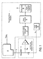
- Figure 1 illustrates a low cost ink drop detector which employs preexisting digital signal processing elements in a printer along with low cost analog sensing elements.
- the preexisting digital signal processing elements include an analog-to-digital converter 18, a printer processor 20, and a memory 22.
- the low cost analog sensing elements include an electrostatic sensing element 14 and a sense amplifier 16.
- the digital signal processing capability provided by the preexisting elements in the printer enables the use of a relatively low sensitivity, low speed and therefore low cost implementation of the sense amplifier 16.
- the digital signal processing enables the extraction of a reliable drop detection value from the low cost amplifier even though the output signal of the low cost amplifier may be lower than its electrical noise.
- a print head 10 is positioned opposite the sensing element 14 at a distance of several millimeters during ink drop detection. In one embodiment, the print head 10 is positioned 3 millimeters away from the sensing element 14.
- the sensing element 14 may be disposed in an existing service station in the printer.
- the sensing element 14 is applied with a voltage potential V 0 by a power supply 24.
- the print head 10 is applied with a drive voltage V DRIVE for actuating the ink drop firing mechanisms of its nozzles.
- the voltage potential V DRIVE applied to the print head 10 is relatively low compared to V 0 .
- V DRIVE is approximately 5 volts and the power supply 24 applies a V 0 of approximately 100 volts. This results in an electric field between the print head 10 and the sensing element 14 of approximately 30 volts/millimeter.
- the print head 10 ejects a series of ink drops 12 during an ink drop test cycle.
- the relatively high electric field between the print head 10 and the sensing element 14 cause the accumulation of electrical charge in the portions of the ink drops 12 closest to the sensing element 14 as they shear away from a nozzle of the print head 10.
- Each of the ink drops 12 separates from the print head 10 it retains its accumulated electrical charge.
- Each of the ink drops 12 thus transports its induced charge to the sensing element 14.
- each of the ink drops 12 imparts a spike or pulse of electrical charge onto the sensing element 14 as it makes contact.
- These spikes or pulses on the sensing element 14 are AC coupled through an input capacitor C IN to an input of the sense amplifier 16.
- the sense amplifier 16 generates an output signal 40 in response to the electrical voltage imparted onto the sensing element 14 by the bursts of the ink drops 12.
- the sense amplifier 15 amplifies the pulses and provides some filtering.
- the sense amplifier 16 is a relatively low cost amplifier which does not have enough sensitivity or speed to detect individual ones of the ink drops 12.
- the sense amplifier 16 is realized with a two-stage single supply operational amplifier implemented on a CMOS integrated circuit chip.
- the first stage is AC coupled to the sensing element 14 and converts the electrical current imparted to the sensing element 14 by the ink drops 12 into a voltage.
- the second stage provides voltage amplification of the first stage voltage output to provide the output signal 40.
- the gain of the second stage is set such that a 1 millisecond current pulse of 200 pico-amps at the input to the first stage results in a 2.5 volt pulse of the output signal 40.
- the ink drops 12 are fired in a series of bursts having a predetermined frequency or pattern of frequencies.
- the sense amplifier 16 is tuned to amplify signals from the sensing element 14 at the frequency or frequencies of the predetermined pattern.
- the output signal 40 from the sense amplifier 16 is provided to an analog-to-digital converter 18 which generates a digitized version. This digitized version of the output signal 40 is provided to the printer processor 20 which executes signal processing code 62.
- the printer processor 20 when executing the signal processing code 62 performs a digital signal processing function on the digitized version of the output signal 40.
- the digital signal processing function performed by the printer processor 20 determines a magnitude of the output signal 40 at the predetermined frequency or pattern of frequencies at which ink drops are ejected from the print head 10. This magnitude provides a drop detection value that is then used to characterize ink drops ejected from the print head 10 during an ink drop test cycle.
- One characteristic which the drop detection value is used to determine is whether any ink drops were ejected during the ink drop test cycle. Another characteristic is the volume of the ink drops ejected during the ink drop test cycle. Another characteristic is the velocity of the ink drops ejected during the ink drop test cycle.
- FIG. 2 illustrates an example pattern of ink drop bursts 30-32 which are fired from the print head 10 during an ink drop test cycle.
- Each of the bursts 30-32 includes a series of eight ink drops.
- each of the bursts 30-32 has a duration of T 0 and a period of T 1 .
- the total number of the bursts 30-32 in an ink drop test cycle is equal to N.
- the predetermined frequency of the bursts 30-32 is 1/T 1 throughout the duration of an ink drop test cycle.
- T 0 is .8 milliseconds and T1 is 1.6 milliseconds which yields a 50 percent duty cycle.
- the predetermined frequency of the bursts 30-32 is 1/1.6 milliseconds or 625 hertz.
- the rate of firing of individual ink drops during each of the bursts 30-32 is 10 kilohertz.
- the sense amplifier 16 is tuned to 625 hertz which is relatively slow compared to the 10 kilohertz rate of nozzle firing from the print head 10.
- a waveform 40 represents the output signal 40 of the sense amplifier 16 in response to the bursts 30-32.
- the waveform 40 has a periodic shape roughly corresponding to the frequency of the bursts 30-32.
- the analog-to-digital converter 18 samples the waveform 40 several times during each cycle of the waveform 40 at equal time intervals. For example, the analog-to-digital converter 18 begins sampling the waveform 40 at time t1 and completes a sample cycle at time t2 which is just before the start of the burst 31. The analog-to-digital converter 18 then begins sampling the next cycle of the waveform 40, which corresponds to the burst 31, at time t3 and so on.
- the bursts 30-32 are ejected from the print head 10 in a predetermined pattern of frequencies.
- a predetermined pattern may be a shifting pattern of frequencies.
- the frequency of the bursts 30-32 may shift from 500 hertz to 525 hertz to 550 hertz and back again to 500 hertz in a repeating pattern.
- Each frequency in the shifting pattern is within the frequency response range of the amplifier 16.
- the shifting pattern of frequencies avoids errors that may be caused by a condition in which a particular frequency of the bursts 30-32 matches a frequency of noise that exists in the environment of the printer.
- the shifting pattern makes it likely that one or more of the frequencies in the pattern will be clear of the noise and be useable for rendering a drop detection value.
- the frequencies in the shifting pattern not be multiples of each other. It is also preferable that the frequencies in the shifting pattern not be harmonics of each other.
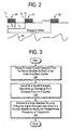
- Figure 3 illustrates one embodiment of the digital signal processing steps performed by the printer processor 20 when executing the signal processing code 62.
- the printer processor 20 uses the analog-to-digital converter 13 to obtain S digitized samples for each of the N cycles of the output signal 40 from the sense amplifier 16.
- the printer processor generates a signal averaged data array by overlaying the S samples for each of the N cycles of the output signal 40 and generating an average value for each of the S samples.
- the averaged values in the signal averaged data array eliminate noise in the output signal 40.
- the signal averaged data array contains S averaged values.
- the printer processor 20 determines a drop detection value from the signal averaged data array by fitting the data array to a target waveform having a frequency equal to the predetermined frequency of the bursts 30-32.
- the signal averaged data array is fit to a function having the following form: A sin( ⁇ t+ ⁇ )
- the amplitude A provides the drop detection value which is the amplitude of the output signal 40 at the predetermined frequency of the bursts 30-32 which is ⁇ .
- ⁇ is equal to 625 Hz.
- the phase angle ⁇ is a characteristic of the particular implementation of the sense amplifier 16 and in one embodiment determined by measurement and stored for the printing processor 20. Alternatively, the phase angle ⁇ can be derived as a variable in the same manner as the amplitude A .
- the target waveform is a square wave having the predetermined burst cycle frequency. In another embodiment, the target waveform is an experimentally derived waveform that matches the actual measured response of the sense amplifier 16.
- the printer processor 20 extracts the drop detection value from the data array by multiplying the data array by a sine array and a cosine array, then summing the results and then taking the square root of the sum of the squares according to the following equation: where
- the printer processor 20 is provided with lookup tables that contain the values for the sine and cosine arrays.
- the digital signal processor 20 performs a fast fourier transformation (FFT) on the digitized version of the output signal 40 and then extracts the amplitude at the frequencies of interest, namely the predetermined frequency of the bursts 30-32.
- FFT fast fourier transformation
- the resulting drop detection value at step 104 is proportional to the number of drops fired from the print head 10.
- the resulting drop detection value is also proportional to the volume of the ink drops ejected and the velocity of the ink drops that were ejected depending upon which characteristic is being determined.
- the drop detection value is a linear function of the number of ink drops in each of the bursts 30-32, the number of nozzles fired during each of the bursts 30-32, and the bias voltage V 0 applied to the sensing element 14 if the velocity and volume of ink drops remain constant.
- the step of signal averaging may be minimized or skipped.
- a drop detection value is determined for each of the frequencies in the predetermined pattern of the bursts 30-32 using the techniques described above or their equivalents. For example, a data array may be generated for each frequency in the predetermined pattern and a waveform matching step may be performed on each of the data arrays. The resulting drop detection values are then used for a variety of determinations as described hereinafter.
- Figure 4 is a graph showing the drop detection value verses the number of ink drops contained in each of the bursts 30-32 of an ink drop test cycle.
- the graph shows the advantage of using ink drop bursts having multiple ink drop firings given the relatively low sensitivity of the sense amplifier 16.
- the sense amplifier 16 yields a low output at the frequency of interest as shown by the graph when 5 or fewer drops are included in each of the bursts 30-32.
- the values in this graph are stored by the printer processor 20 for subsequent use when detecting ink drops or characterizing ink drops ejected from the print head 10.
- the data for this graph may be preprogrammed into a table in the signal processing code 62 at the time of manufacture or the printer processor 20 may gather the data at any time after manufacture.
- the printer processor 20 compares the drop detection value or values obtained from a ink drop test cycle to the stored representation of this graph to determine the number of drops fired by the print head 10 during the ink drop test cycle. For example, if the drop detection value from an ink drop test cycle is within a tolerance value of the number N1, then it can be concluded that 10 ink drops struck the sensing element 14 during each the bursts 30-32. If the drive control electronics for the print head 10 actuated 10 firings per burst then it can be concluded that the particular nozzle of the print head 10 under test is functioning properly. If, on the other hand, the drive control electronics actuated 10 firings and the resulting drop detection value is significantly below N1 then it can be concluded that the particular nozzle under test is not functioning properly.
- the drop detection values is useful for rendering a go/no-go decision on each of the nozzles in the print head 10.
- the printer processor 20 opportunistically tests a few nozzles on the fly at the end of a print cycle on a page. If the drop detection value from a particular ink drop test cycle is too low then the printer applies the print head 10 to the service station in the printer. If after cleaning several times the particular nozzle or nozzles are still bad then the printer processor 20 can adjust its printing algorithm embodied in the printing code 60 to compensate for the bad nozzle or provide an error indication to a user of the printer that the print head 10 should be replaced.
- the drop detection value is also useful for characterizing the individual nozzles of the print head 10 in order to enhance gray scale or color resolution.
- the printer processor 20 can obtain cumulative drop detection values for each of the nozzles of the print head 10. This per nozzle drop detection data may be used to estimate the size or volume of the individual drops ejected by particular nozzles in the print head 10 on a per nozzle basis.
- the volume of ink drops from individual nozzles can vary due to process variation during manufacture of the print head 10.
- the volume of ink drops from a particular nozzle may also vary over time as the print head 10 is in extended use.
- the printer processor 20 can use the per nozzle drop detection data to adjust the numbers of ink drops ejected from particular nozzles for a desired gray scale level.
- the drop detection value is also useful for adjusting the drive voltages to individual ones or groups of nozzles in a thermal print head in order to enhance the life of the heating elements contained therein.
- Process control variations during manufacture of a thermal print head can cause certain ones of the nozzles to fire at higher or lower drive voltages that others.
- groups of nozzles may require higher drive voltages due to bussing variation in a thermal print head as well as process control variations among the nozzles.
- these turn on energy levels for individual nozzles can vary over time with extended use of the thermal print head.
- the printer processor 20 could conduct firing trials on individual nozzles or groups of nozzles to detect the minimum level of drive voltage required to fire ink drops.
- the printer processor 20 varies the drive voltages or the pulse width of the drive voltages until the drop detection value indicates optimum drive conditions for a particular nozzle.
- the printer processor 20 selects a minimum voltage operating point that will extend the life of the heating elements in the thermal print head.
- Figures 5a-5c show various configurations for the sensing element 14.
- the sensing element is contained in a trough or spittoon that accepts test ink drops fired from the print head 10.
- the spittoon prevents test ink drops from contaminating other parts of the printer.
- the spittoon may be an existing spittoon in the service station of a printer or may be an additional spittoon provided for ink drop detection.
- Figure 5a shows the sensing element 14 as a layer of electrically conductive plastic foam disposed in a spittoon 50.
- the foam layer 14 is compressible and absorbs ink drops to prevent printer contamination.
- the layer 14 is electrically coupled to the input capacitor C IN for the sense amplifier 16 by an electrical signal line (not shown).
- Figure 5b shows the sensing element 14 as a grid of fine stainless steel wire positioned at the opening of a spittoon 54.
- the stainless steel wire 14 is electrically coupled to the input capacitor C IN for the sense amplifier 16 by an electrical signal line (not shown).
- the spittoon 54 contains a layer 52 of nonconductive foam that absorbs the test ink drops.
- FIG. 5c shows an application specific integrated circuit (ASIC) 64 contained in the trough of a spittoon 54.
- the ASIC 64 implements the circuitry of the sense amplifier 16.
- the ASIC 64 is encapsulated by an insulating layer 68.
- the sensing element 14 is a metal layer disposed on top of the insulating layer 68 and is electrically coupled to circuitry on the ASIC 64 through a via 66 through the insulating layer 68.
- a layer 60 of insulating foam covers the trough of the spittoon 56.
- the sensing element 14 may be positioned beneath a paper path in a printing area opposite the print head 10.
- a sensing element 14 may be constructed of a conductive pad of foam or a metallic or a conductive plastic member.
Landscapes
- Ink Jet (AREA)
- Particle Formation And Scattering Control In Inkjet Printers (AREA)
Claims (15)
- Détecteur de salves de gouttes d'encre, comprenant :un élément détecteur (14) qui reçoit un stimulus électrique chaque fois qu'il est touché par une goutte d'encre dans une série de salves de gouttes d'encre qui sont éjectées d'une tête d'impression (10) ;un amplificateur de lecture (16) couplé à l'élément détecteur, et des moyens de traitement (18, 20, 22) reliés à l'amplificateur de lecture, caractérisés en ce que :des moyens sont fournis pour produire une différence de potentiel entre la tête d'impression et l'élément détecteur, moyennant quoi une charge électrique est créée qui s'accumule dans les gouttes d'encre éjectées, ledit stimulus électrique consistant en l'application de la charge accumulée sur l'élément détecteur, en ce sens que l'amplificateur de lecture est réglé sur une fréquence à laquelle les salves de gouttes d'encre sont éjectées de la tête d'impression, et en ce sens que le moyen de traitement détermine l'amplitude d'un signal de sortie produit par l'amplificateur de lecture à la fréquence à laquelle les salves de gouttes d'encre doivent être éjectées, de telle manière que l'amplitude indique une caractéristique des gouttes d'encre éjectées pendant chaque salve.
- Détecteur de gouttes d'encre selon la revendication 1, dans lequel le moyen de traitement détermine l'amplitude en exécutant une fonction de traitement du signal numérique sur le signal de sortie.
- Détecteur de gouttes d'encre selon la revendication 1, dans lequel la caractéristique est de savoir si des gouttes d'encre ont été éjectées pendant chaque salve.
- Détecteur de gouttes d'encre selon la revendication 1, dans lequel la caractéristique est le volume de gouttes d'encre pour chaque salve.
- Détecteur de gouttes d'encre selon la revendication 1, dans lequel la caractéristique est la vitesse des gouttes d'encre pour chaque salve.
- Détecteur de gouttes d'encre selon l'une quelconque des revendications 1 à 5, dans lequel l'élément détecteur est contenu dans un crachoir.
- Détecteur de gouttes d'encre selon l'une quelconque des revendications 1 à 5, dans lequel l'élément détecteur est positionné sur une surface d'impression faisant face à la tête d'impression.
- Procédé de détection des salves de gouttes d'encre d'une tête d'impression, comprenant les étapes de :production d'un signal électrique en réponse à chacune des séries de salves de gouttes d'encre de la tête d'impression ;détection et amplification des signaux électriques de manière à produire un signal de sortie à une fréquence à laquelle les salves sont éjectées de la tête d'impression et ;détermination d'une amplitude du signal de sortie à la fréquence, en exécutant une fonction de traitement du signal numérique sur le signal de sortie, de telle manière que l'amplitude indique une caractéristique des gouttes d'encre pour chaque salve, le signal électrique étant généré par la production d'une différence de potentiel entre ladite tête d'impression et le moyen de détection, moyennant quoi une charge électrique est créée qui s'accumule dans les gouttes d'encre éjectées, et ledit signal électrique est créé en appliquant la charge accumulée sur le moyen de détection.
- Procédé selon la revendication 8, dans lequel l'amplitude indique un volume des gouttes d'encre éjectées par la tête d'impression.
- Procédé selon la revendication 8, dans lequel l'étape de détermination de l'amplitude comprend les étapes de numérisation du signal de sortie de manière à générer un tableau de données, et de faire ensuite correspondre le tableau de données à un objectif sous forme d'onde ayant la fréquence.
- Procédé selon la revendication 8, dans lequel l'étape de détermination de l'amplitude est effectuée au moyen d'un processeur préexistant et d'un convertisseur analogique numérique préexistant dans une imprimante qui contient la tête d'impression.
- Détecteur de gouttes d'encre, comprenant :un élément détecteur qui reçoit un stimulus électrique quand il entre en contact avec une série de salves de gouttes d'encre éjectées d'une tête d'impression dans laquelle les salves de gouttes d'encre se produisent selon un modèle prédéterminé de fréquences ; caractérisé en ce que le détecteur de gouttes d'encre comprend en outre :des moyens pour produire une différence de potentiel entre la tête d'impression et l'élément détecteur, moyennant quoi une charge électrique est créée qui s'accumule dans les gouttes d'encre éjectées, ledit stimulus électrique consistant dans l'application de la charge accumulée sur l'élément détecteur ;un amplificateur de lecture qui est réglé sur le modèle prédéterminé de fréquences, l'amplificateur de lecture produisant un signal de sortie en réponse aux salves de gouttes d'encre entrant en contact avec l'élément détecteur ;un moyen de traitement qui détermine une amplitude du signal de sortie pour chaque fréquence du modèle prédéterminé de fréquences, de telle manière que chaque amplitude fournisse une caractérisation des gouttes d'encre pour chaque salve correspondante.
- Détecteur de gouttes d'encre selon la revendication 12, dans lequel le moyen de traitement détermine les amplitudes en exécutant une fonction de traitement du signal numérique sur le signal de sortie pour chaque fréquence du modèle prédéterminé de fréquences.
- Détecteur de gouttes d'encre selon l'une des revendications 12 ou 13, dans lequel le modèle prédéterminé de fréquences est présélectionné pour éviter des résultats erronés dans la détermination des amplitudes qui sont provoqués par le bruit dans l'amplificateur de lecture.
- Détecteur de gouttes d'encre selon la revendication 12, dans lequel le moyen de traitement détermine les amplitudes en numérisant le signal de sortie, de manière à générer un tableau de données pour chaque fréquence du modèle prédéterminé, et en faisant ensuite correspondre chaque tableau de données à un objectif sous forme d'onde ayant une fréquence correspondante dans le modèle prédéterminé.
Applications Claiming Priority (2)
| Application Number | Priority Date | Filing Date | Title |
|---|---|---|---|
| US08/946,190 US6086190A (en) | 1997-10-07 | 1997-10-07 | Low cost ink drop detector |
| US946190 | 1997-10-07 |
Publications (3)
| Publication Number | Publication Date |
|---|---|
| EP0908315A2 EP0908315A2 (fr) | 1999-04-14 |
| EP0908315A3 EP0908315A3 (fr) | 1999-11-17 |
| EP0908315B1 true EP0908315B1 (fr) | 2003-03-12 |
Family
ID=25484077
Family Applications (1)
| Application Number | Title | Priority Date | Filing Date |
|---|---|---|---|
| EP98308138A Expired - Lifetime EP0908315B1 (fr) | 1997-10-07 | 1998-10-06 | Détection de gouttes d'encre |
Country Status (4)
| Country | Link |
|---|---|
| US (1) | US6086190A (fr) |
| EP (1) | EP0908315B1 (fr) |
| JP (1) | JPH11170569A (fr) |
| DE (1) | DE69812025T2 (fr) |
Families Citing this family (52)
| Publication number | Priority date | Publication date | Assignee | Title |
|---|---|---|---|---|
| US6375299B1 (en) * | 1998-11-02 | 2002-04-23 | Encad, Inc. | Faulty ink ejector detection in an ink jet printer |
| US6315383B1 (en) | 1999-12-22 | 2001-11-13 | Hewlett-Packard Company | Method and apparatus for ink-jet drop trajectory and alignment error detection and correction |
| US6998230B1 (en) * | 2000-04-26 | 2006-02-14 | Agilent Technologies, Inc. | Array fabrication with drop detection |
| EP1203945B1 (fr) * | 2000-10-26 | 2006-12-20 | Agilent Technologies, Inc. (a Delaware corporation) | Microechantillons |
| US6460964B2 (en) | 2000-11-29 | 2002-10-08 | Hewlett-Packard Company | Thermal monitoring system for determining nozzle health |
| US6454374B1 (en) | 2001-01-31 | 2002-09-24 | Hewlett-Packard Company | Uni-directional waste ink removal system |
| US6454373B1 (en) | 2001-01-31 | 2002-09-24 | Hewlett-Packard Company | Ink drop detector waste ink removal system |
| US6533377B2 (en) | 2001-01-31 | 2003-03-18 | Hewlett-Packard Company | Cleaning system for cleaning ink residue from a sensor |
| US6692099B2 (en) * | 2001-04-30 | 2004-02-17 | Hewlett-Packard Development Company, L.P. | Testing nozzles in print heads |
| US6474772B1 (en) | 2001-07-17 | 2002-11-05 | Hewlett-Packard Company | Method of determining thermal turn on energy |
| US6536865B2 (en) | 2001-07-25 | 2003-03-25 | Hewlett-Packard Company | Method and apparatus for detecting printer service station capacity |
| US6769756B2 (en) * | 2001-07-25 | 2004-08-03 | Hewlett-Packard Development Company, L.P. | Ink drop detector configurations |
| US6550887B2 (en) | 2001-07-25 | 2003-04-22 | Christopher B. Miller | Ink drop detector |
| US6612677B2 (en) | 2001-07-25 | 2003-09-02 | Hewlett-Packard Company | Ink drop sensor |
| US6491366B1 (en) | 2001-08-20 | 2002-12-10 | Hewlett-Packard Company | Ink drop detector waste ink removal system |
| US6454376B1 (en) * | 2001-08-27 | 2002-09-24 | Hewlett-Packard Company | Determining inkjet printer pen turn-on voltages |
| US6530640B1 (en) | 2001-08-29 | 2003-03-11 | Hewlett-Packard Company | Focused ink drop detection |
| US6513901B1 (en) | 2001-09-28 | 2003-02-04 | Hewlett-Packard Company | Method and apparatus for determining drop volume from a drop ejection device |
| US6533384B1 (en) | 2001-10-30 | 2003-03-18 | Hewlett-Packard Company | System and method for selective printhead based servicing operations |
| US6561614B1 (en) | 2001-10-30 | 2003-05-13 | Hewlett-Packard Company | Ink system characteristic identification |
| JP3697209B2 (ja) | 2001-12-27 | 2005-09-21 | キヤノン株式会社 | 液体吐出検出方法及びその装置とインクジェット記録装置 |
| US6578946B1 (en) * | 2002-03-22 | 2003-06-17 | Hewlett-Packard Development Company, L.P. | Movable ink drop detector pick up for a drop-on-demand printer |
| US6742864B2 (en) | 2002-04-30 | 2004-06-01 | Hewlett-Packard Development Company, L.P. | Waste ink removal system |
| US7101508B2 (en) * | 2002-07-31 | 2006-09-05 | Agilent Technologies, Inc. | Chemical array fabrication errors |
| US6837561B2 (en) * | 2002-10-30 | 2005-01-04 | Xerox Corporation | Current switching architecture for head driver of solid ink jet print heads |
| US6814419B2 (en) | 2002-10-30 | 2004-11-09 | Xerox Corporation | Normalization of head driver current for solid ink jet printhead |
| US6793306B2 (en) | 2002-10-30 | 2004-09-21 | Xerox Corporation | Normalization of head driver current for solid ink jet printhead by current slop adjustment |
| JP4227395B2 (ja) | 2002-11-14 | 2009-02-18 | キヤノン株式会社 | 液滴吐出状態判定方法及び装置とインクジェットプリンタ及びそのプログラムと記憶媒体 |
| US7025433B2 (en) | 2002-11-27 | 2006-04-11 | Hewlett-Packard Development Company, L.P. | Changing drop-ejection velocity in an ink-jet pen |
| US7013804B2 (en) * | 2003-12-16 | 2006-03-21 | Lexmark International, Inc. | Method of ink level determination for multiple ink chambers |
| JP4079127B2 (ja) * | 2004-07-01 | 2008-04-23 | セイコーエプソン株式会社 | 検査装置及び液滴吐出検査方法 |
| JP4910283B2 (ja) * | 2004-11-09 | 2012-04-04 | セイコーエプソン株式会社 | 吐出検査装置、液体滴吐出装置、及び吐出検査方法 |
| US7503637B2 (en) | 2004-11-10 | 2009-03-17 | Seiko Epson Corporation | Liquid-ejection testing method, liquid-ejection testing device, and computer-readable medium |
| US7134328B2 (en) | 2004-11-10 | 2006-11-14 | Seiko Epson Corporation | Liquid-ejection testing method, liquid-ejection testing device, and computer-readable medium |
| JP2006142554A (ja) | 2004-11-17 | 2006-06-08 | Seiko Epson Corp | 液体吐出検査装置、液体吐出検査方法、液体吐出装置、印刷装置、プログラム、および液体吐出システム |
| US20070024658A1 (en) * | 2005-07-28 | 2007-02-01 | Eastman Kodak Company | Apparatus and method for detection of liquid droplets |
| JP5011672B2 (ja) * | 2005-08-04 | 2012-08-29 | セイコーエプソン株式会社 | 印刷ヘッド検査装置、印刷装置、印刷ヘッド検査方法 |
| US7673976B2 (en) * | 2005-09-16 | 2010-03-09 | Eastman Kodak Company | Continuous ink jet apparatus and method using a plurality of break-off times |
| US7434919B2 (en) * | 2005-09-16 | 2008-10-14 | Eastman Kodak Company | Ink jet break-off length measurement apparatus and method |
| JP5017931B2 (ja) * | 2005-09-30 | 2012-09-05 | セイコーエプソン株式会社 | 画像形成装置、印刷ヘッド検査方法及びそのプログラム |
| JP4311418B2 (ja) | 2006-07-24 | 2009-08-12 | セイコーエプソン株式会社 | ノズル検査装置およびノズル検査方法 |
| DE112007003370B4 (de) * | 2007-02-27 | 2019-08-08 | Hewlett-Packard Development Company, L.P. | Graphische Diagnosedarstellung von Druckköpfen |
| JP5281275B2 (ja) | 2007-11-27 | 2013-09-04 | セイコーエプソン株式会社 | 吐出検査装置、記録装置、吐出検査方法及び吐出検査プログラム |
| JP4905380B2 (ja) * | 2008-02-08 | 2012-03-28 | セイコーエプソン株式会社 | 駆動信号設定方法 |
| JP2009189954A (ja) * | 2008-02-14 | 2009-08-27 | Seiko Epson Corp | 駆動信号設定方法 |
| JP5369757B2 (ja) * | 2009-02-27 | 2013-12-18 | 株式会社リコー | インク滴検出装置、インクジェットプリンタ及びインク滴検出方法 |
| JP5088708B2 (ja) * | 2010-02-18 | 2012-12-05 | セイコーエプソン株式会社 | 液体吐出検査装置および液体吐出検査方法 |
| JP2011189667A (ja) * | 2010-03-16 | 2011-09-29 | Ricoh Co Ltd | インクジェット記録装置 |
| WO2012083980A1 (fr) * | 2010-12-21 | 2012-06-28 | Baumer Innotec Ag | Tête d'impression à jet d'encre à contrôle optique intégré de la fonction de buse |
| JP2014097642A (ja) * | 2012-11-15 | 2014-05-29 | Ricoh Co Ltd | 画像形成装置 |
| US9154093B2 (en) | 2013-01-25 | 2015-10-06 | Hewlett-Packard Development Company, L.P. | Liquid drop detection using backscattered light with amplifiers |
| US9073374B1 (en) * | 2014-03-31 | 2015-07-07 | Xerox Corporation | System for detecting inoperative inkjets in three-dimensional object printing using a test pattern and electrical continuity probes |
Family Cites Families (10)
| Publication number | Priority date | Publication date | Assignee | Title |
|---|---|---|---|---|
| US4067019A (en) * | 1976-06-14 | 1978-01-03 | International Business Machines Corporation | Impact position transducer for ink jet |
| US4128841A (en) * | 1977-09-28 | 1978-12-05 | Burroughs Corporation | Droplet microphone |
| US4310846A (en) * | 1978-12-28 | 1982-01-12 | Ricoh Company, Ltd. | Deflection compensated ink ejection printing apparatus |
| US4323905A (en) * | 1980-11-21 | 1982-04-06 | Ncr Corporation | Ink droplet sensing means |
| US4333083A (en) * | 1980-12-23 | 1982-06-01 | International Business Machines Corporation | Electrostatic drop sensor with sensor diagnostics for ink jet printers |
| US4636809A (en) * | 1985-10-21 | 1987-01-13 | Videojet Systems International, Inc. | Ink catcher and drop charge sensing device |
| US4872028A (en) * | 1988-03-21 | 1989-10-03 | Hewlett-Packard Company | Thermal-ink-jet print system with drop detector for drive pulse optimization |
| US4878064A (en) * | 1988-10-31 | 1989-10-31 | Eastman Kodak Company | Continuous ink jet stimulation adjustment based on overdrive detection |
| US5036340A (en) * | 1989-01-31 | 1991-07-30 | Hewlett-Packard Company | Piezoelectric detector for drop position determination in multi-pen ink jet printing systems |
| JP2891439B2 (ja) * | 1992-03-02 | 1999-05-17 | シルバー精工株式会社 | 連続噴射型インクジェット記録装置および そのインクジェット飛翔軸自動調整方法 |
-
1997
- 1997-10-07 US US08/946,190 patent/US6086190A/en not_active Expired - Lifetime
-
1998
- 1998-10-01 JP JP10280064A patent/JPH11170569A/ja active Pending
- 1998-10-06 EP EP98308138A patent/EP0908315B1/fr not_active Expired - Lifetime
- 1998-10-06 DE DE69812025T patent/DE69812025T2/de not_active Expired - Lifetime
Also Published As
| Publication number | Publication date |
|---|---|
| US6086190A (en) | 2000-07-11 |
| DE69812025D1 (de) | 2003-04-17 |
| DE69812025T2 (de) | 2004-03-04 |
| EP0908315A2 (fr) | 1999-04-14 |
| EP0908315A3 (fr) | 1999-11-17 |
| JPH11170569A (ja) | 1999-06-29 |
Similar Documents
| Publication | Publication Date | Title |
|---|---|---|
| EP0908315B1 (fr) | Détection de gouttes d'encre | |
| US6517183B2 (en) | Method for detecting drops in printer device | |
| US6375299B1 (en) | Faulty ink ejector detection in an ink jet printer | |
| US4323905A (en) | Ink droplet sensing means | |
| EP2955026B1 (fr) | Dispositif et procédé d'éjection de gouttelettes liquides et appareil d'enregistrement à jet d'encre | |
| CN110402199A (zh) | 包括应变计传感器的流体喷射管芯 | |
| US4484199A (en) | Method and apparatus for detecting failure of an ink jet printing device | |
| US9340048B2 (en) | Inkjet print head health detection | |
| JP2004160889A (ja) | 液滴吐出状態判定方法 | |
| WO1998025768A1 (fr) | Detecteur de gouttes pour appareil a jet d'encre | |
| US8388089B2 (en) | Printing device, discharge test device and discharge test method | |
| US4994821A (en) | Continuous ink jet printer apparatus having improved short detection construction | |
| US7108349B2 (en) | Print head charge shield | |
| JP4022805B2 (ja) | インクジェット式プリンタのインク残量検出装置及び検出方法 | |
| US6604807B1 (en) | Method and apparatus for detecting anomalous nozzles in an ink jet printer device | |
| JP2012196774A (ja) | 吐出検査装置 | |
| US11794472B2 (en) | Method and apparatus for continuous inkjet printing | |
| US4631549A (en) | Method and apparatus for adjusting stimulation amplitude in continuous ink jet printer | |
| US20110085001A1 (en) | Ejection Examination Apparatus and Printing Apparatus | |
| JP2012196773A (ja) | 吐出検査方法 | |
| JPS60112454A (ja) | インクジエツト記録装置 | |
| JPS60112453A (ja) | インクジエツト記録装置 |
Legal Events
| Date | Code | Title | Description |
|---|---|---|---|
| PUAI | Public reference made under article 153(3) epc to a published international application that has entered the european phase |
Free format text: ORIGINAL CODE: 0009012 |
|
| AK | Designated contracting states |
Kind code of ref document: A2 Designated state(s): DE FR GB |
|
| AX | Request for extension of the european patent |
Free format text: AL;LT;LV;MK;RO;SI |
|
| PUAL | Search report despatched |
Free format text: ORIGINAL CODE: 0009013 |
|
| AK | Designated contracting states |
Kind code of ref document: A3 Designated state(s): AT BE CH CY DE DK ES FI FR GB GR IE IT LI LU MC NL PT SE |
|
| AX | Request for extension of the european patent |
Free format text: AL;LT;LV;MK;RO;SI |
|
| 17P | Request for examination filed |
Effective date: 20000221 |
|
| AKX | Designation fees paid |
Free format text: DE FR GB |
|
| RAP1 | Party data changed (applicant data changed or rights of an application transferred) |
Owner name: HEWLETT-PACKARD COMPANY, A DELAWARE CORPORATION |
|
| 17Q | First examination report despatched |
Effective date: 20010418 |
|
| GRAG | Despatch of communication of intention to grant |
Free format text: ORIGINAL CODE: EPIDOS AGRA |
|
| GRAG | Despatch of communication of intention to grant |
Free format text: ORIGINAL CODE: EPIDOS AGRA |
|
| GRAH | Despatch of communication of intention to grant a patent |
Free format text: ORIGINAL CODE: EPIDOS IGRA |
|
| GRAH | Despatch of communication of intention to grant a patent |
Free format text: ORIGINAL CODE: EPIDOS IGRA |
|
| GRAA | (expected) grant |
Free format text: ORIGINAL CODE: 0009210 |
|
| AK | Designated contracting states |
Designated state(s): DE FR GB |
|
| REG | Reference to a national code |
Ref country code: GB Ref legal event code: FG4D |
|
| REF | Corresponds to: |
Ref document number: 69812025 Country of ref document: DE Date of ref document: 20030417 Kind code of ref document: P |
|
| ET | Fr: translation filed | ||
| PLBE | No opposition filed within time limit |
Free format text: ORIGINAL CODE: 0009261 |
|
| STAA | Information on the status of an ep patent application or granted ep patent |
Free format text: STATUS: NO OPPOSITION FILED WITHIN TIME LIMIT |
|
| 26N | No opposition filed |
Effective date: 20031215 |
|
| REG | Reference to a national code |
Ref country code: GB Ref legal event code: 732E Free format text: REGISTERED BETWEEN 20120329 AND 20120404 |
|
| PGFP | Annual fee paid to national office [announced via postgrant information from national office to epo] |
Ref country code: FR Payment date: 20121107 Year of fee payment: 15 Ref country code: DE Payment date: 20121029 Year of fee payment: 15 |
|
| PGFP | Annual fee paid to national office [announced via postgrant information from national office to epo] |
Ref country code: GB Payment date: 20121025 Year of fee payment: 15 |
|
| GBPC | Gb: european patent ceased through non-payment of renewal fee |
Effective date: 20131006 |
|
| PG25 | Lapsed in a contracting state [announced via postgrant information from national office to epo] |
Ref country code: GB Free format text: LAPSE BECAUSE OF NON-PAYMENT OF DUE FEES Effective date: 20131006 |
|
| REG | Reference to a national code |
Ref country code: FR Ref legal event code: ST Effective date: 20140630 |
|
| REG | Reference to a national code |
Ref country code: DE Ref legal event code: R119 Ref document number: 69812025 Country of ref document: DE Effective date: 20140501 |
|
| PG25 | Lapsed in a contracting state [announced via postgrant information from national office to epo] |
Ref country code: DE Free format text: LAPSE BECAUSE OF NON-PAYMENT OF DUE FEES Effective date: 20140501 Ref country code: FR Free format text: LAPSE BECAUSE OF NON-PAYMENT OF DUE FEES Effective date: 20131031 |