EP0908285A2 - Verfahren zum Herstellen eines Kunststoffisolators - Google Patents
Verfahren zum Herstellen eines Kunststoffisolators Download PDFInfo
- Publication number
- EP0908285A2 EP0908285A2 EP98308343A EP98308343A EP0908285A2 EP 0908285 A2 EP0908285 A2 EP 0908285A2 EP 98308343 A EP98308343 A EP 98308343A EP 98308343 A EP98308343 A EP 98308343A EP 0908285 A2 EP0908285 A2 EP 0908285A2
- Authority
- EP
- European Patent Office
- Prior art keywords
- forming
- polymer insulator
- end cap
- cavity
- die
- Prior art date
- Legal status (The legal status is an assumption and is not a legal conclusion. Google has not performed a legal analysis and makes no representation as to the accuracy of the status listed.)
- Withdrawn
Links
Images


Classifications
-
- H—ELECTRICITY
- H01—ELECTRIC ELEMENTS
- H01B—CABLES; CONDUCTORS; INSULATORS; SELECTION OF MATERIALS FOR THEIR CONDUCTIVE, INSULATING OR DIELECTRIC PROPERTIES
- H01B19/00—Apparatus or processes specially adapted for manufacturing insulators or insulating bodies
-
- B—PERFORMING OPERATIONS; TRANSPORTING
- B29—WORKING OF PLASTICS; WORKING OF SUBSTANCES IN A PLASTIC STATE IN GENERAL
- B29C—SHAPING OR JOINING OF PLASTICS; SHAPING OF MATERIAL IN A PLASTIC STATE, NOT OTHERWISE PROVIDED FOR; AFTER-TREATMENT OF THE SHAPED PRODUCTS, e.g. REPAIRING
- B29C43/00—Compression moulding, i.e. applying external pressure to flow the moulding material; Apparatus therefor
- B29C43/02—Compression moulding, i.e. applying external pressure to flow the moulding material; Apparatus therefor of articles of definite length, i.e. discrete articles
- B29C43/18—Compression moulding, i.e. applying external pressure to flow the moulding material; Apparatus therefor of articles of definite length, i.e. discrete articles incorporating preformed parts or layers, e.g. compression moulding around inserts or for coating articles
-
- B—PERFORMING OPERATIONS; TRANSPORTING
- B29—WORKING OF PLASTICS; WORKING OF SUBSTANCES IN A PLASTIC STATE IN GENERAL
- B29C—SHAPING OR JOINING OF PLASTICS; SHAPING OF MATERIAL IN A PLASTIC STATE, NOT OTHERWISE PROVIDED FOR; AFTER-TREATMENT OF THE SHAPED PRODUCTS, e.g. REPAIRING
- B29C43/00—Compression moulding, i.e. applying external pressure to flow the moulding material; Apparatus therefor
- B29C43/32—Component parts, details or accessories; Auxiliary operations
- B29C43/36—Moulds for making articles of definite length, i.e. discrete articles
- B29C43/42—Moulds for making articles of definite length, i.e. discrete articles for undercut articles
-
- B—PERFORMING OPERATIONS; TRANSPORTING
- B29—WORKING OF PLASTICS; WORKING OF SUBSTANCES IN A PLASTIC STATE IN GENERAL
- B29C—SHAPING OR JOINING OF PLASTICS; SHAPING OF MATERIAL IN A PLASTIC STATE, NOT OTHERWISE PROVIDED FOR; AFTER-TREATMENT OF THE SHAPED PRODUCTS, e.g. REPAIRING
- B29C70/00—Shaping composites, i.e. plastics material comprising reinforcements, fillers or preformed parts, e.g. inserts
- B29C70/68—Shaping composites, i.e. plastics material comprising reinforcements, fillers or preformed parts, e.g. inserts by incorporating or moulding on preformed parts, e.g. inserts or layers, e.g. foam blocks
- B29C70/70—Completely encapsulating inserts
-
- B—PERFORMING OPERATIONS; TRANSPORTING
- B29—WORKING OF PLASTICS; WORKING OF SUBSTANCES IN A PLASTIC STATE IN GENERAL
- B29L—INDEXING SCHEME ASSOCIATED WITH SUBCLASS B29C, RELATING TO PARTICULAR ARTICLES
- B29L2031/00—Other particular articles
- B29L2031/34—Electrical apparatus, e.g. sparking plugs or parts thereof
- B29L2031/3412—Insulators
-
- Y—GENERAL TAGGING OF NEW TECHNOLOGICAL DEVELOPMENTS; GENERAL TAGGING OF CROSS-SECTIONAL TECHNOLOGIES SPANNING OVER SEVERAL SECTIONS OF THE IPC; TECHNICAL SUBJECTS COVERED BY FORMER USPC CROSS-REFERENCE ART COLLECTIONS [XRACs] AND DIGESTS
- Y10—TECHNICAL SUBJECTS COVERED BY FORMER USPC
- Y10T—TECHNICAL SUBJECTS COVERED BY FORMER US CLASSIFICATION
- Y10T29/00—Metal working
- Y10T29/49—Method of mechanical manufacture
- Y10T29/49002—Electrical device making
- Y10T29/49227—Insulator making
Definitions
- the present invention relates to a method of forming a polymer insulator, particularly relates to a forming method in which polymer insulators having various shed numbers can be formed without reconstructing a die used for forming.
- Polymer insulators are a known type in which an insulating core rod, e.g. of fibre-reinforced plastics (FRP), is surrounded by a moulded body of plastics material, e.g. silicone rubber, which includes one or more sheds.
- FRP fibre-reinforced plastics
- the present invention is concerend with the shaping of the moulded body on the rod, to prepare the insulator to which the metal end fittings are subsequently attached.
- Figs. 5a to 5d are schematic views showing successive steps of forming the polymer insulator by means of the known compression forming.
- a formed body 34 is prepared.
- the formed body 34 has a construction such that a pre-form material 32 made of silicone rubber is arranged around an FRP rod 31 and end caps 33 are arranged at both end portions of the FRP rod 31. It should be noted that a winding amount of the pre-form material 32 is determined corresponding to the number of sheds.
- a cavity having a predetermined shape is arranged at a side surface of the end cap 33 to which the pre-form material 32 is contacted. Then, the pre-form material 32 is filled in the cavity when performing the compression forming.
- the thus prepared formed body 34 is set between an upper die 41 and a lower die 42.
- Each of the upper die 41 and the lower die 42 has cavities 35 used for forming sheds and sheath portions of the polymer insulator and also cavities 36 used for accommodating the end cap 33.
- the upper die 41 and the lower die 42 are respectively constructed by integrating a plurality of segments 43, and, prior to the compression forming, they are constructed corresponding to the number of sheds of the polymer insulator to be formed.
- the upper die 41 is pressed to the lower die 42 so as to perform the compression forming.
- the upper die 41 is detached from the lower die 42, and further the end caps 33 are removed from the FRP rod 31 so as to obtain a polymer insulator formed body 51.
- the thus obtained polymer insulator formed body 51 has an overcoat layer comprising sheds 52 and sheath portions 53, which is arranged around the FRP rod 31, and also has securing metal fitting connection portion 54 at its both end portions.
- Projection portions 55 are arranged on an entire circumferential surface of the securing metal fitting connection portion 54. These projection portions 55 are served as an O ring when a securing metal fitting not shown is connected to the securing metal fitting connection portion 54. Therefore, it is possible to improve seal performance of a connection boundary between the securing metal fitting and the overcoat layer.
- An object of the invention is to eliminate the drawbacks mentioned above and to provide a method of forming a polymer insulator in which polymer insulators having various shed numbers can be formed without reconstructing a die used for forming.
- a method of forming a polymer insulator comprises the steps of: setting a formed body, having a construction such that a pre-form material is arranged around a rod and end caps are arranged at both end portions of the rod, between an upper die and a lower die, each die having cavities for forming sheds and sheath portions of the polymer insulator; and forming the sheds and the sheath portions of the polymer insulator by means of a compression forming by connecting the upper die and the lower die with compression pressure; wherein the end cap has a shape such that it is accommodated in the cavity for a shed formation.
- the end cap which can be accommodated in the cavity for a shed formation of the polymer insulator, is used. Therefore, if the shed number of the polymer insulator to be formed is varied, it is possible to form the polymer insulators with different shed number without reconstructing the die only by changing an insertion position of the end cap in the cavities for the shed formation. Moreover, under some circumstances, it is possible to form a plurality of polymer insulators at the same time by using the same die.
- a portion of the end cap which is accommodated in the cavity for a shed formation has a height larger than a thickness of the pre-form material, a handling of the formed body before setting becomes easier.
- a portion of the end cap which is accommodated in the cavity for a shed formation has a circular plate shape having a ridge cross section, it is possible to easily insert such a portion of the end cap into the cavity for a shed formation even when a shape of the cavity is varied.
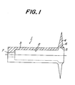
- Fig. 1 is a schematic view showing one embodiment of an end cap used for a method of forming a polymer insulator according to the invention.
- an end cap 1 according to the invention comprises: an end cap main body 3 having a cylindrical shape in which a hole 2 for inserting an FRP rod therein is arranged at its center portion; and a projection portion 4 for a positioning which is extended vertically with respect to a central axis of the cap main body 3 at an open end portion of the end cap main body 3.
- a step portion 5 is arranged at an open end portion side of the end cap main body 3 to form a cavity.
- This cavity serves for forming a securing metal fitting connection portion for an overcoat layer by filling silicone rubber therein under a condition such that an FRP rod 6 is inserted into the hole 2.
- a recess 6 is formed in the step portion 5.
- a small hole 7 for an air discharge which is communicated with the hole 2 is arranged at a closed end portion opposite to the open end portion of the end cap main body 3.
- the projection portion 4 of the end cap 1 has a shape such that it is accommodated in the cavity for a shed formation of a die.
- the projection portion 4 has a circular plate shape having a ridge cross section, thereby achieving an easy insertion into the cavity for a shed formation having a tapered cross section.
- the projection portion 4 has a height H larger than a thickness of the pre-form material.
- end caps 1 can bind overall both ends of the pre-form material when setting the formed body in the die, a handling of the formed body becomes easier.
- an outer root portion 4a of the projection portion 4, to which the pre-form material is not contacted, is accommodated in the cavity for a shed formation with no space when an upper die and a lower die are connected during the compression forming. In this case, it is possible to receive a pressure from the pre-form material during the compression forming without slipping the end caps 1.
- Figs. 2a to 2d are schematic views respectively showing successive steps for forming a polymer insulator according to the invention by using the end cap 1 having the construction shown in Fig. 1. These steps are same as the known steps shown in Figs. 5a to 5d except that the end cap 1 having the construction shown in Fig. 1 is used.
- a pre-form material 12 made of silicone rubber is wound around an FRP rod 11 and the end caps 1 having the construction shown in Fig. 1 are arranged to the FRP rod 11 at both ends of the pre-form material 12 to prepare a formed body 14.
- a positioning operation between the FRP rod 11 and the end cap 1 is performed in such a manner that the end portion of the FRP rod 11 is set to be connected with a bottom portion of the hole 2 of the end cap 1.
- the thus prepared formed body 14 is set between an upper die 21 and a lower die 22.
- Each of the upper die 21 and the lower die 22 has cavities 15 for forming sheds and sheath portions of the polymer insulator.
- the upper die 21 and the lower die 22 are respectively constructed by integrating a plurality of segments 23.
- the upper die 21 and the lower die 22 are assembled prior to perform a forming operation corresponding to the number of sheds of the polymer insulator to be formed.
- the upper die 21 is pressed to the lower die 22 to perform a compression forming.
- the projection portion 4 of the end cap 1 has a shape such that it is accommodated in the cavity 15 for a shed formation, it is not necessary to use a special cavity for accommodating the end cap according to the known method.
- the upper die 21 is detached from the lower die 22 and further the end caps 1 are removed from the FRP rod 11 to obtain a polymer insulator formed body 31 as shown in Fig. 2d.
- the projection portion 4 of the end cap 1 has a shape such that it can be accommodated in the cavity 15. Therefore, if a position of the end cap 1 with respect to the FRP rod 11 is varied in response to the number of sheds of the polymer insulator to be formed, the following using types (1)-(3) can be achieved without reconstructing the dies (21 and 22):
- the polymer insulator to be formed has the same shape and the same diameter of the FRP rod 11, it is possible to form the polymer insulator by one same dies without reconstructing (re-assembling) the dies (21 and 22).
- portions such as the FRP rod 11 and the pre-form material 12 are omitted here.
- the present invention is not limited to the embodiment mentioned above, but various modifications are possible.
- the end cap which can be accommodated in the cavity for a shed formation of the polymer insulator, is used. Therefore, if the shed number of the polymer insulator to be formed is varied, it is possible to form the polymer insulators with different shed number without reconstructing the die only by changing an insertion position of the end cap in the cavities for the shed formation.
- the end cap which can be accommodated in the cavity for a shed formation of the polymer insulator, is used. Therefore, if the shed number of the polymer insulator to be formed is varied, it is possible to form the polymer insulators with different shed number without reconstructing the die only by changing an insertion position of the end cap in the cavities for the shed formation. Moreover, under some circumstances, it is possible to form a plurality of polymer insulators at the same time by using the same die.
Applications Claiming Priority (3)
| Application Number | Priority Date | Filing Date | Title |
|---|---|---|---|
| JP278318/97 | 1997-10-13 | ||
| JP27831897A JP3157756B2 (ja) | 1997-10-13 | 1997-10-13 | ポリマー碍子の成形方法 |
| JP27831897 | 1997-10-13 |
Publications (2)
| Publication Number | Publication Date |
|---|---|
| EP0908285A2 true EP0908285A2 (de) | 1999-04-14 |
| EP0908285A3 EP0908285A3 (de) | 2000-07-05 |
Family
ID=17595670
Family Applications (1)
| Application Number | Title | Priority Date | Filing Date |
|---|---|---|---|
| EP98308343A Withdrawn EP0908285A3 (de) | 1997-10-13 | 1998-10-13 | Verfahren zum Herstellen eines Kunststoffisolators |
Country Status (3)
| Country | Link |
|---|---|
| US (1) | US6105248A (de) |
| EP (1) | EP0908285A3 (de) |
| JP (1) | JP3157756B2 (de) |
Cited By (1)
| Publication number | Priority date | Publication date | Assignee | Title |
|---|---|---|---|---|
| CN109215903A (zh) * | 2017-11-08 | 2019-01-15 | 襄阳国网合成绝缘子有限责任公司 | 一种超/特高压复合绝缘子拉套成型工艺及其拉套工装 |
Families Citing this family (4)
| Publication number | Priority date | Publication date | Assignee | Title |
|---|---|---|---|---|
| US6326552B1 (en) * | 1999-12-01 | 2001-12-04 | Hubbel Incorporated | Insulator end fitting with non-machined annular attachment flange |
| WO2018226780A1 (en) | 2017-06-06 | 2018-12-13 | West Pharmaceuticals Services, Inc. | Elastomer articles having embedded electronics and method of manufacturing the same |
| JP7023988B2 (ja) | 2017-06-06 | 2022-02-22 | ウエスト ファーマスーティカル サービシーズ インコーポレイテッド | 埋込み電子機器を有するエラストマーアーティクルおよびその製造方法 |
| US11581111B2 (en) | 2020-08-20 | 2023-02-14 | Te Connectivity Solutions Gmbh | Composite polymer insulators and methods for forming same |
Citations (5)
| Publication number | Priority date | Publication date | Assignee | Title |
|---|---|---|---|---|
| JPS592806A (ja) * | 1982-06-30 | 1984-01-09 | Matsushita Electric Works Ltd | 枠用の成形金型 |
| US4670973A (en) * | 1985-01-25 | 1987-06-09 | Alsthom-Atlantique S.A. | Method of making an insulating stay |
| EP0624446A1 (de) * | 1993-03-26 | 1994-11-17 | Ngk Insulators, Ltd. | Verfahren und Vorrichtung zum Herstellen von Isolatoren |
| US5484564A (en) * | 1992-12-28 | 1996-01-16 | Ngk Insulators, Ltd. | Method for manufacturing a long non-ceramic insulator in mold longitudinally shorter than the insulator |
| US5804122A (en) * | 1996-03-18 | 1998-09-08 | Ngk Insulators, Ltd. | Method of producing composite insulator |
Family Cites Families (4)
| Publication number | Priority date | Publication date | Assignee | Title |
|---|---|---|---|---|
| US4045604A (en) * | 1974-10-08 | 1977-08-30 | Raychem Limited | Recoverable article with outwardly extending hollow heat flanges; kit including such article and a cylindrical substrate; and method of making such article |
| GB8312892D0 (en) * | 1983-05-11 | 1983-06-15 | Raychem Ltd | Electrical insulator |
| GB8333249D0 (en) * | 1983-12-13 | 1984-01-18 | Raychem Ltd | Electrically insulating articles |
| GB8923408D0 (en) * | 1989-10-17 | 1989-12-06 | Raychem Ltd | Electrical insulator |
-
1997
- 1997-10-13 JP JP27831897A patent/JP3157756B2/ja not_active Expired - Fee Related
-
1998
- 1998-10-09 US US09/169,364 patent/US6105248A/en not_active Expired - Fee Related
- 1998-10-13 EP EP98308343A patent/EP0908285A3/de not_active Withdrawn
Patent Citations (5)
| Publication number | Priority date | Publication date | Assignee | Title |
|---|---|---|---|---|
| JPS592806A (ja) * | 1982-06-30 | 1984-01-09 | Matsushita Electric Works Ltd | 枠用の成形金型 |
| US4670973A (en) * | 1985-01-25 | 1987-06-09 | Alsthom-Atlantique S.A. | Method of making an insulating stay |
| US5484564A (en) * | 1992-12-28 | 1996-01-16 | Ngk Insulators, Ltd. | Method for manufacturing a long non-ceramic insulator in mold longitudinally shorter than the insulator |
| EP0624446A1 (de) * | 1993-03-26 | 1994-11-17 | Ngk Insulators, Ltd. | Verfahren und Vorrichtung zum Herstellen von Isolatoren |
| US5804122A (en) * | 1996-03-18 | 1998-09-08 | Ngk Insulators, Ltd. | Method of producing composite insulator |
Cited By (1)
| Publication number | Priority date | Publication date | Assignee | Title |
|---|---|---|---|---|
| CN109215903A (zh) * | 2017-11-08 | 2019-01-15 | 襄阳国网合成绝缘子有限责任公司 | 一种超/特高压复合绝缘子拉套成型工艺及其拉套工装 |
Also Published As
| Publication number | Publication date |
|---|---|
| EP0908285A3 (de) | 2000-07-05 |
| JPH11120848A (ja) | 1999-04-30 |
| US6105248A (en) | 2000-08-22 |
| JP3157756B2 (ja) | 2001-04-16 |
Similar Documents
| Publication | Publication Date | Title |
|---|---|---|
| US4572605A (en) | Injection molded in-line connector assembly for bipolar leads | |
| CA1255884A (en) | Method of manufacturing contact spring sockets | |
| WO2008060142A1 (en) | Method for making a catheter | |
| US6105248A (en) | Method of forming polymer insulator | |
| US4691079A (en) | Screw-on wire connector | |
| CN107866986B (zh) | 制造支柱的方法以及由此形成的支柱 | |
| CA2444828A1 (en) | Polymeric cutout assembly | |
| AU689213B2 (en) | Method of manufacturing an electrofusion coupler | |
| CN2658981Y (zh) | 一种塞帽和它的构造 | |
| US6317102B1 (en) | Method and tool for manufacturing an antenna unit, and an antenna unit | |
| EP1817823A1 (de) | Verfahren zur herstellung eines kommutators sowie kommutator | |
| EP0836237A1 (de) | Gratfreier korrosionsbeständiger Pol mit kurzer Verankerung für Speicherbatterien | |
| US5612508A (en) | Flexible jumper and method of making | |
| EP4040585A1 (de) | Modulgehäuse, verfahren zum herstellen eines modulgehäuses und batteriemodul | |
| EP1043734B1 (de) | Elektrischer Verbundisolator, sein Montageverfahren und sein Herstellungsverfahren | |
| JP2000326100A (ja) | 傾斜面を有する圧粉体の成形方法 | |
| US2401451A (en) | Process of making jack plugs | |
| US6379602B1 (en) | Method of producing outer coating layer of polymer insulator | |
| US6894597B2 (en) | Axially potted progressive wound remote mount ignition coil | |
| JPH02273488A (ja) | 電気部品およびその製造方法 | |
| CA2544526A1 (en) | Method of manufacturing a molding with a core | |
| JP2001283665A (ja) | ポリマー碍子の圧縮成形法 | |
| JPS5939435Y2 (ja) | エキスパンド鋼心アルミより線用充てん線插入装置 | |
| CN209823069U (zh) | 压接模具部件和压接模具 | |
| CN208706580U (zh) | 一种to46-5pin管座的接地脚阵列装配模具 |
Legal Events
| Date | Code | Title | Description |
|---|---|---|---|
| PUAI | Public reference made under article 153(3) epc to a published international application that has entered the european phase |
Free format text: ORIGINAL CODE: 0009012 |
|
| AK | Designated contracting states |
Kind code of ref document: A2 Designated state(s): DE FR IT |
|
| AX | Request for extension of the european patent |
Free format text: AL;LT;LV;MK;RO;SI |
|
| PUAL | Search report despatched |
Free format text: ORIGINAL CODE: 0009013 |
|
| AK | Designated contracting states |
Kind code of ref document: A3 Designated state(s): AT BE CH CY DE DK ES FI FR GB GR IE IT LI LU MC NL PT SE |
|
| AX | Request for extension of the european patent |
Free format text: AL;LT;LV;MK;RO;SI |
|
| 17P | Request for examination filed |
Effective date: 20001221 |
|
| AKX | Designation fees paid |
Free format text: DE FR IT |
|
| GRAH | Despatch of communication of intention to grant a patent |
Free format text: ORIGINAL CODE: EPIDOS IGRA |
|
| STAA | Information on the status of an ep patent application or granted ep patent |
Free format text: STATUS: THE APPLICATION IS DEEMED TO BE WITHDRAWN |
|
| 18D | Application deemed to be withdrawn |
Effective date: 20030423 |