EP0908271A2 - Schleifkopf mit oszillierenden Werkzeugträgern - Google Patents
Schleifkopf mit oszillierenden Werkzeugträgern Download PDFInfo
- Publication number
- EP0908271A2 EP0908271A2 EP98830162A EP98830162A EP0908271A2 EP 0908271 A2 EP0908271 A2 EP 0908271A2 EP 98830162 A EP98830162 A EP 98830162A EP 98830162 A EP98830162 A EP 98830162A EP 0908271 A2 EP0908271 A2 EP 0908271A2
- Authority
- EP
- European Patent Office
- Prior art keywords
- toolholders
- lapping head
- toothing
- head according
- driving shaft
- Prior art date
- Legal status (The legal status is an assumption and is not a legal conclusion. Google has not performed a legal analysis and makes no representation as to the accuracy of the status listed.)
- Granted
Links
Images

Classifications
-
- B—PERFORMING OPERATIONS; TRANSPORTING
- B24—GRINDING; POLISHING
- B24B—MACHINES, DEVICES, OR PROCESSES FOR GRINDING OR POLISHING; DRESSING OR CONDITIONING OF ABRADING SURFACES; FEEDING OF GRINDING, POLISHING, OR LAPPING AGENTS
- B24B41/00—Component parts such as frames, beds, carriages, headstocks
- B24B41/04—Headstocks; Working-spindles; Features relating thereto
- B24B41/047—Grinding heads for working on plane surfaces
- B24B41/0475—Grinding heads for working on plane surfaces equipped with oscillating abrasive blocks, e.g. mounted on a rotating head
-
- B—PERFORMING OPERATIONS; TRANSPORTING
- B24—GRINDING; POLISHING
- B24B—MACHINES, DEVICES, OR PROCESSES FOR GRINDING OR POLISHING; DRESSING OR CONDITIONING OF ABRADING SURFACES; FEEDING OF GRINDING, POLISHING, OR LAPPING AGENTS
- B24B37/00—Lapping machines or devices; Accessories
- B24B37/11—Lapping tools
-
- B—PERFORMING OPERATIONS; TRANSPORTING
- B24—GRINDING; POLISHING
- B24B—MACHINES, DEVICES, OR PROCESSES FOR GRINDING OR POLISHING; DRESSING OR CONDITIONING OF ABRADING SURFACES; FEEDING OF GRINDING, POLISHING, OR LAPPING AGENTS
- B24B37/00—Lapping machines or devices; Accessories
-
- B—PERFORMING OPERATIONS; TRANSPORTING
- B24—GRINDING; POLISHING
- B24B—MACHINES, DEVICES, OR PROCESSES FOR GRINDING OR POLISHING; DRESSING OR CONDITIONING OF ABRADING SURFACES; FEEDING OF GRINDING, POLISHING, OR LAPPING AGENTS
- B24B37/00—Lapping machines or devices; Accessories
- B24B37/27—Work carriers
Definitions
- the present invention refers to a lapping head with oscillating toolholders for use, in particular, in lapping and/or polishing machines for working stone materials such as marble, granite, preferably, etc.
- heads with oscillating toolholders for the polishing and lapping of stone materials said heads having a vertical shaft connected, on one side, to a corresponding driving shaft and, on the other, to a case to drive the latter into rotation at a predetermined speed.
- a fixed reaction flange Disposed between the case and the member from which the motor receives the motion is a fixed reaction flange supported by the case by means of bearings having their axis parallel to the axis of the shaft.
- the case bears a plurality of toolholder elements to which corresponding abrasive tools may be attached and which are driven into oscillatory motion about their respective axis via a mechanical transmission connected to said driving motor, so that each abrasive tool will be driven into an oscillatory motion about the axis of its toolholder and, at the same time, into rotary motion about the axis of the driving motor.
- a further operating technique use is also made of machines having cylindrical grinding wheels. Heads for lapping machines of this type are described, for example, in the patents EP-571.340, IT-1.198.798 and IT-FI-96-U-00062.
- the kinematic link allowing for the transmission of the motion from the main shaft to the various toolholders may be carried out in several ways.
- use can be made of cams of suitable shape (tubolar, for instance), or of eccentrics; practical solutions are also known which adopt special connecting rods, or levers, or rockers provided with rollers which interact with relevant cam means.
- the main object of the present invention is to provide a lapping head in which the driving shaft moves the toolholhers into an oscillatory motion thanks to means for the transmission of motion which comprise a plurality of gears (pivoted on corresponding toolholders) and a crown gear connected to the driving shaft and to be driven by the latter, the same crown gear being connected to the said gears through the association of two toothings one of which exhibits at least a variation of inclination along its development; the toolholders are pivoted to said support body so as to oscillate when said toothings mesh with each other in correspondence of a portion thereof exhibiting said variation of inclination.
- means for the transmission of motion which comprise a plurality of gears (pivoted on corresponding toolholders) and a crown gear connected to the driving shaft and to be driven by the latter, the same crown gear being connected to the said gears through the association of two toothings one of which exhibits at least a variation of inclination along its development; the toolholders are pivoted to said support body so as to oscil
- the present solution makes it possible to use a higher working speed, with an extremely uniform oscillation of the tool and without the dead times and accelerations which characterize the prior techinque.
- the present lapping head allows a more efficent production and a better quality of the finished product.
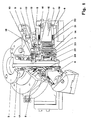
- a lapping head with oscillating toolholders constructed according to the present invention comprises a driving shaft (1) carrying on top a flange (2) which defines the means (2) associated to relevant driving means.
- the flange (2) allows for the attachment of the lapping head to the spindle of a machine, the latter being not shown in the drawings as it does not make part of the present invention.
- the lapping head further comprises a plurality of toolholders, (6) connected to the driving shaft (1) by means of first and second drive means, to be described herebelow.
- the first drive means comprise a first body (5) supporting the toolholders (6) and which is secured by screws (4) to a flange (3) provided in the lower portion of the driving shaft (1) so as to result integral thereto upon the rotary motion of the same shaft.
- the second drive means are intended to cause, in correspondence of the rotation of the driving shaft (1), an oscillation of the toolholders (6) about their axes (7) disposed at an angle to the driving shaft (1); in particular, the shaft (7) of the toolholders (6) may be disposed radially and substantially perpendicular to the driving shaft (1) - as shown in the non limitative example in which they are in an unbinding number of six.
- the second means for the transmission of the motion comprise, in general, at least a plurality of first gears (15), pivoted on the toolholders (6) and a crown gear (12) connected to the driving shaft (1) and to be driven by the latter.
- a gear train (8, 9) may be provided between the crown gear (12) and the driving shaft (1) as illustrated in the example.
- the third gear (9) has two inner toothings (10, 11) for meshing respectively with said second gear (8) and a first toothing (13) borne by the crown gear (12).
- the crown gear (12) is made to mesh with the first gears (15) through the association of two toothings (14, 15') one of which exhibits at least one variation of inclination along its development; the toolholders (6), moreover, by pivoting with respect to the support body (5), are caused to oscillate when the meshing of said toothings takes place in correspondence of a portion thereof exhibiting said variation of inclination.
- the toothing exhibiting at least one variation of inclination along its development may be provided either on the crown gear (12) or on the first gears (15).
- the special toothing (14) is formed on the crown gear (12).
- the special toothing (14) alternates straigth and inclined portions.
- two straight teeth or spaces may be provided in correspondence of the origin (0° is coincident with 360°) and the mid point.
- the teeth In the 0° to 90° portion (designated with 14a) the teeth become oblique, with the maximum inclination being at 90°. From this point on, in the portion 14b, the inclination decreases [gradually] to become zero at 180°. From 180° to 270° (portion 14c) the teeth are again oblique but with an inclination opposite to that of the portions 14a and 14b.
- the speed of oscillation of the toolholders (6) is determined by the number of sectors or portions into which the special toothing (14) is divided, as well as by the transmission ratio of the gearing defined by the second gear (8), by the third gear (9) with its two toothings (10) and (11), and by the crown gear (12) with its toothing (13).
- the first gears (15) may be supported by corresponding pins (16) provided on the toolholders (6) and be disposed substantially perpendicular to the shafts (7).
- the present lapping head makes it possible to obtain an alternate and continuous radial motion.
- Such motion is obtained by making the special toothing (14) eccentric with respect to the driving shaft (1), or by making the gears (15) eccentric with respect to the relevant pins (16).
- the radial motion described above will result proportional to the diametral variation or to the degree of eccentricity of the special toothing (14) (or of the gears (15)).
- the radial motion will result extremely adtantageous in case of the so-called dressing of diamond tools.
- the shafts (7) may result engaged to the first support body (5) through a bush (19) associated to the same shafts (7) by a connection comprising a clearance-recovery device, for example, with springs (20) and balls (21), as shown in the drawings.
- the support body (5) may be made to oscillate with respect to the driving shaft (1) by spring elements (22) and (23).
- spring elements (22) and (23) On the first support body (5), in correspondence of the portions intended to face the toolholders (6), corresponding swells (24) may be provided coincident with the relevant axes of the shafts (7).
- an inner cavity (18) may be provided which defines a chamber for storing a lubricating fluid.
Landscapes
- Engineering & Computer Science (AREA)
- Mechanical Engineering (AREA)
- Finish Polishing, Edge Sharpening, And Grinding By Specific Grinding Devices (AREA)
- Gear Transmission (AREA)
- Cutting Tools, Boring Holders, And Turrets (AREA)
- Wind Motors (AREA)
- Constituent Portions Of Griding Lathes, Driving, Sensing And Control (AREA)
- Polishing Bodies And Polishing Tools (AREA)
- Magnetic Heads (AREA)
- Crushing And Grinding (AREA)
Applications Claiming Priority (2)
| Application Number | Priority Date | Filing Date | Title |
|---|---|---|---|
| IT97FI000223A IT1295664B1 (it) | 1997-10-09 | 1997-10-09 | Testa lucidatrice a portasettori oscillanti |
| ITFI970223 | 1997-10-09 |
Publications (3)
| Publication Number | Publication Date |
|---|---|
| EP0908271A2 true EP0908271A2 (de) | 1999-04-14 |
| EP0908271A3 EP0908271A3 (de) | 2001-01-31 |
| EP0908271B1 EP0908271B1 (de) | 2002-10-23 |
Family
ID=11352259
Family Applications (1)
| Application Number | Title | Priority Date | Filing Date |
|---|---|---|---|
| EP98830162A Expired - Lifetime EP0908271B1 (de) | 1997-10-09 | 1998-03-20 | Schleifkopf mit oszillierenden Werkzeugträgern |
Country Status (7)
| Country | Link |
|---|---|
| EP (1) | EP0908271B1 (de) |
| KR (1) | KR100384374B1 (de) |
| BR (1) | BR9801586A (de) |
| DE (1) | DE69808869T2 (de) |
| ES (1) | ES2185138T3 (de) |
| IT (1) | IT1295664B1 (de) |
| TW (1) | TW431951B (de) |
Cited By (6)
| Publication number | Priority date | Publication date | Assignee | Title |
|---|---|---|---|---|
| WO2009090551A1 (en) * | 2008-01-18 | 2009-07-23 | Co.Me.S S.R.L. | 'head for the treatment of stone and ceramic material |
| WO2010106389A1 (en) * | 2009-03-18 | 2010-09-23 | Co.Me.S. S.R.L. | Head for the treatment of stone and ceramic materials |
| ITRE20110103A1 (it) * | 2011-11-28 | 2013-05-29 | B M R S P A | Testa per la levigatura e/o lucidatura di corpi sostanzialmente lastriformi |
| CN108942636A (zh) * | 2018-06-29 | 2018-12-07 | 江苏中科晶元信息材料有限公司 | 一种用于生产砷化镓的自动研磨机 |
| IT201900001429A1 (it) * | 2019-01-31 | 2020-07-31 | Simec Spa | Testa di calibratura e/o levigatura |
| IT202000004387A1 (it) | 2020-03-02 | 2021-09-02 | Ancora Spa | Testa per il trattamento di lastre in materiale ceramico e simili |
Families Citing this family (3)
| Publication number | Priority date | Publication date | Assignee | Title |
|---|---|---|---|---|
| KR100416375B1 (ko) * | 2000-08-21 | 2004-01-31 | 오군재 | 화강석 연마헤드 |
| CN108673336A (zh) * | 2018-07-18 | 2018-10-19 | 窦业正 | 一种打磨机用磨头 |
| CN111761504B (zh) * | 2020-07-07 | 2022-03-18 | 温州职业技术学院 | 一种家具生产用环保型表面处理装置 |
Family Cites Families (3)
| Publication number | Priority date | Publication date | Assignee | Title |
|---|---|---|---|---|
| IT1258733B (it) * | 1992-05-22 | 1996-02-27 | Testa per macchina lucidatrice con portasettori oscillanti | |
| IT1267682B1 (it) * | 1994-02-09 | 1997-02-07 | Simec Spa | Testa di lucidatura, particolarmente per lastre di marmo, granito, gres porcellanato ed altri materiali lapidei |
| IT1278641B1 (it) * | 1995-04-14 | 1997-11-27 | Comes Srl | Testa perfezionata per macchine lucidatrici con bracci portasettori oscillanti |
-
1997
- 1997-10-09 IT IT97FI000223A patent/IT1295664B1/it active IP Right Grant
-
1998
- 1998-03-20 ES ES98830162T patent/ES2185138T3/es not_active Expired - Lifetime
- 1998-03-20 EP EP98830162A patent/EP0908271B1/de not_active Expired - Lifetime
- 1998-03-20 DE DE69808869T patent/DE69808869T2/de not_active Expired - Lifetime
- 1998-03-25 TW TW087104452A patent/TW431951B/zh not_active IP Right Cessation
- 1998-05-06 BR BR9801586A patent/BR9801586A/pt not_active IP Right Cessation
- 1998-06-19 KR KR10-1998-0023035A patent/KR100384374B1/ko not_active Expired - Fee Related
Cited By (6)
| Publication number | Priority date | Publication date | Assignee | Title |
|---|---|---|---|---|
| WO2009090551A1 (en) * | 2008-01-18 | 2009-07-23 | Co.Me.S S.R.L. | 'head for the treatment of stone and ceramic material |
| WO2010106389A1 (en) * | 2009-03-18 | 2010-09-23 | Co.Me.S. S.R.L. | Head for the treatment of stone and ceramic materials |
| ITRE20110103A1 (it) * | 2011-11-28 | 2013-05-29 | B M R S P A | Testa per la levigatura e/o lucidatura di corpi sostanzialmente lastriformi |
| CN108942636A (zh) * | 2018-06-29 | 2018-12-07 | 江苏中科晶元信息材料有限公司 | 一种用于生产砷化镓的自动研磨机 |
| IT201900001429A1 (it) * | 2019-01-31 | 2020-07-31 | Simec Spa | Testa di calibratura e/o levigatura |
| IT202000004387A1 (it) | 2020-03-02 | 2021-09-02 | Ancora Spa | Testa per il trattamento di lastre in materiale ceramico e simili |
Also Published As
| Publication number | Publication date |
|---|---|
| EP0908271A3 (de) | 2001-01-31 |
| KR100384374B1 (ko) | 2003-07-16 |
| ES2185138T3 (es) | 2003-04-16 |
| IT1295664B1 (it) | 1999-05-24 |
| DE69808869D1 (de) | 2002-11-28 |
| ITFI970223A1 (it) | 1999-04-09 |
| KR19990036531A (ko) | 1999-05-25 |
| EP0908271B1 (de) | 2002-10-23 |
| BR9801586A (pt) | 1999-06-01 |
| HK1019213A1 (en) | 2000-01-28 |
| DE69808869T2 (de) | 2003-09-11 |
| TW431951B (en) | 2001-05-01 |
| ITFI970223A0 (it) | 1997-10-09 |
Similar Documents
| Publication | Publication Date | Title |
|---|---|---|
| EP0908271B1 (de) | Schleifkopf mit oszillierenden Werkzeugträgern | |
| CN100408270C (zh) | 抛光机 | |
| CN1074971C (zh) | 具有摆动工具夹的研磨头 | |
| JPS631472B2 (de) | ||
| US3093939A (en) | Surfacing apparatus | |
| US3745715A (en) | Honing apparatus | |
| US3925936A (en) | Lapping machine | |
| BR9809841A (pt) | Cabeça polidora com segmentos abrasivos tendo movimento tangencial oscilante contìnuo, para materiais de granito, pedra dura ou cerâmica na forma de placas | |
| JPH0551425B2 (de) | ||
| EP0510603B1 (de) | Schleifkopf, insbesondere zum Schleifen von Marmor, Granit und Gestein im allgemeinen | |
| WO2009090551A1 (en) | 'head for the treatment of stone and ceramic material | |
| US4982532A (en) | Method and apparatus for finishing gear tooth surfaces of a bevel gear | |
| JPH0413076Y2 (de) | ||
| HK1019213B (en) | Lapping head with oscillating toolholders | |
| SU1678584A1 (ru) | Способ правки притиров | |
| EP0301152A2 (de) | Schalttellermaschine mit elektrischer Steuerung | |
| SU1207735A1 (ru) | Устройство дл сообщени осциллирующего движени шпинделю станка | |
| JP3083787B2 (ja) | ホーニング加工方法およびホーニング装置 | |
| RU2062213C1 (ru) | Устройство для двусторонней доводки плоскостей | |
| SU878532A1 (ru) | Устройство дл доводки деталей | |
| GB2269125A (en) | Precision-grinding of the cams on camshafts | |
| RU2176586C1 (ru) | Устройство для абразивной обработки плоских поверхностей | |
| SU1738609A1 (ru) | Способ плоского торцового шлифовани | |
| SU933402A1 (ru) | Виброцентробежна установка | |
| SU448119A1 (ru) | Устройство дл получени асферических поверхностей |
Legal Events
| Date | Code | Title | Description |
|---|---|---|---|
| PUAI | Public reference made under article 153(3) epc to a published international application that has entered the european phase |
Free format text: ORIGINAL CODE: 0009012 |
|
| AK | Designated contracting states |
Kind code of ref document: A2 Designated state(s): DE ES FR IT PT |
|
| AX | Request for extension of the european patent |
Free format text: AL;LT;LV;MK;RO;SI |
|
| RIN1 | Information on inventor provided before grant (corrected) |
Inventor name: SIGNORINI, ROBERTO |
|
| PUAL | Search report despatched |
Free format text: ORIGINAL CODE: 0009013 |
|
| AK | Designated contracting states |
Kind code of ref document: A3 Designated state(s): AT BE CH DE DK ES FI FR GB GR IE IT LI LU MC NL PT SE |
|
| AX | Request for extension of the european patent |
Free format text: AL;LT;LV;MK;RO;SI |
|
| 17P | Request for examination filed |
Effective date: 20010223 |
|
| AKX | Designation fees paid |
Free format text: DE ES FR IT PT |
|
| GRAG | Despatch of communication of intention to grant |
Free format text: ORIGINAL CODE: EPIDOS AGRA |
|
| GRAG | Despatch of communication of intention to grant |
Free format text: ORIGINAL CODE: EPIDOS AGRA |
|
| GRAH | Despatch of communication of intention to grant a patent |
Free format text: ORIGINAL CODE: EPIDOS IGRA |
|
| 17Q | First examination report despatched |
Effective date: 20020422 |
|
| GRAH | Despatch of communication of intention to grant a patent |
Free format text: ORIGINAL CODE: EPIDOS IGRA |
|
| GRAA | (expected) grant |
Free format text: ORIGINAL CODE: 0009210 |
|
| AK | Designated contracting states |
Kind code of ref document: B1 Designated state(s): DE ES FR IT PT |
|
| REF | Corresponds to: |
Ref document number: 69808869 Country of ref document: DE Date of ref document: 20021128 |
|
| PG25 | Lapsed in a contracting state [announced via postgrant information from national office to epo] |
Ref country code: PT Free format text: LAPSE BECAUSE OF FAILURE TO SUBMIT A TRANSLATION OF THE DESCRIPTION OR TO PAY THE FEE WITHIN THE PRESCRIBED TIME-LIMIT Effective date: 20030123 |
|
| REG | Reference to a national code |
Ref country code: ES Ref legal event code: FG2A Ref document number: 2185138 Country of ref document: ES Kind code of ref document: T3 |
|
| ET | Fr: translation filed | ||
| PLBE | No opposition filed within time limit |
Free format text: ORIGINAL CODE: 0009261 |
|
| STAA | Information on the status of an ep patent application or granted ep patent |
Free format text: STATUS: NO OPPOSITION FILED WITHIN TIME LIMIT |
|
| 26N | No opposition filed |
Effective date: 20030724 |
|
| REG | Reference to a national code |
Ref country code: FR Ref legal event code: PLFP Year of fee payment: 19 |
|
| REG | Reference to a national code |
Ref country code: FR Ref legal event code: PLFP Year of fee payment: 20 |
|
| PGFP | Annual fee paid to national office [announced via postgrant information from national office to epo] |
Ref country code: FR Payment date: 20170327 Year of fee payment: 20 |
|
| PGFP | Annual fee paid to national office [announced via postgrant information from national office to epo] |
Ref country code: IT Payment date: 20170324 Year of fee payment: 20 |
|
| PGFP | Annual fee paid to national office [announced via postgrant information from national office to epo] |
Ref country code: DE Payment date: 20170531 Year of fee payment: 20 |
|
| PGFP | Annual fee paid to national office [announced via postgrant information from national office to epo] |
Ref country code: ES Payment date: 20170425 Year of fee payment: 20 |
|
| REG | Reference to a national code |
Ref country code: DE Ref legal event code: R071 Ref document number: 69808869 Country of ref document: DE |
|
| REG | Reference to a national code |
Ref country code: ES Ref legal event code: FD2A Effective date: 20210205 |
|
| PG25 | Lapsed in a contracting state [announced via postgrant information from national office to epo] |
Ref country code: ES Free format text: LAPSE BECAUSE OF EXPIRATION OF PROTECTION Effective date: 20180321 |