EP0908264B1 - Vorrichtung zum Härten der Innenkontur eines Waffenrohres mit Laserstrahlung - Google Patents
Vorrichtung zum Härten der Innenkontur eines Waffenrohres mit Laserstrahlung Download PDFInfo
- Publication number
- EP0908264B1 EP0908264B1 EP98116447A EP98116447A EP0908264B1 EP 0908264 B1 EP0908264 B1 EP 0908264B1 EP 98116447 A EP98116447 A EP 98116447A EP 98116447 A EP98116447 A EP 98116447A EP 0908264 B1 EP0908264 B1 EP 0908264B1
- Authority
- EP
- European Patent Office
- Prior art keywords
- laser
- gun barrel
- laser head
- optics
- hardening
- Prior art date
- Legal status (The legal status is an assumption and is not a legal conclusion. Google has not performed a legal analysis and makes no representation as to the accuracy of the status listed.)
- Expired - Lifetime
Links
- 239000007789 gas Substances 0.000 claims description 9
- 230000005855 radiation Effects 0.000 claims description 6
- IJGRMHOSHXDMSA-UHFFFAOYSA-N Atomic nitrogen Chemical compound N#N IJGRMHOSHXDMSA-UHFFFAOYSA-N 0.000 claims description 4
- 238000001816 cooling Methods 0.000 claims description 4
- 230000001681 protective effect Effects 0.000 claims description 4
- 239000000835 fiber Substances 0.000 claims description 3
- 238000000034 method Methods 0.000 claims description 3
- 230000007547 defect Effects 0.000 claims description 2
- 229910052757 nitrogen Inorganic materials 0.000 claims description 2
- 238000011109 contamination Methods 0.000 claims 1
- 239000013307 optical fiber Substances 0.000 description 5
- 230000009466 transformation Effects 0.000 description 5
- XKRFYHLGVUSROY-UHFFFAOYSA-N Argon Chemical compound [Ar] XKRFYHLGVUSROY-UHFFFAOYSA-N 0.000 description 2
- VYZAMTAEIAYCRO-UHFFFAOYSA-N Chromium Chemical compound [Cr] VYZAMTAEIAYCRO-UHFFFAOYSA-N 0.000 description 2
- 229910000831 Steel Inorganic materials 0.000 description 2
- 230000002950 deficient Effects 0.000 description 2
- 238000012545 processing Methods 0.000 description 2
- 239000010959 steel Substances 0.000 description 2
- 229910001080 W alloy Inorganic materials 0.000 description 1
- NKRHXEKCTWWDLS-UHFFFAOYSA-N [W].[Cr].[Co] Chemical compound [W].[Cr].[Co] NKRHXEKCTWWDLS-UHFFFAOYSA-N 0.000 description 1
- 238000010521 absorption reaction Methods 0.000 description 1
- 229910045601 alloy Inorganic materials 0.000 description 1
- 239000000956 alloy Substances 0.000 description 1
- 229910052786 argon Inorganic materials 0.000 description 1
- 230000005540 biological transmission Effects 0.000 description 1
- 230000015572 biosynthetic process Effects 0.000 description 1
- 229910052804 chromium Inorganic materials 0.000 description 1
- 239000011651 chromium Substances 0.000 description 1
- 239000011248 coating agent Substances 0.000 description 1
- 239000002826 coolant Substances 0.000 description 1
- 238000013461 design Methods 0.000 description 1
- 230000002542 deteriorative effect Effects 0.000 description 1
- 230000003628 erosive effect Effects 0.000 description 1
- 238000002474 experimental method Methods 0.000 description 1
- 239000003365 glass fiber Substances 0.000 description 1
- 230000020169 heat generation Effects 0.000 description 1
- 238000003754 machining Methods 0.000 description 1
- 229910052751 metal Inorganic materials 0.000 description 1
- 239000002184 metal Substances 0.000 description 1
- 238000012544 monitoring process Methods 0.000 description 1
- 239000003380 propellant Substances 0.000 description 1
- 230000001105 regulatory effect Effects 0.000 description 1
- 238000004381 surface treatment Methods 0.000 description 1
- 238000005406 washing Methods 0.000 description 1
- XLYOFNOQVPJJNP-UHFFFAOYSA-N water Substances O XLYOFNOQVPJJNP-UHFFFAOYSA-N 0.000 description 1
Images
Classifications
-
- C—CHEMISTRY; METALLURGY
- C21—METALLURGY OF IRON
- C21D—MODIFYING THE PHYSICAL STRUCTURE OF FERROUS METALS; GENERAL DEVICES FOR HEAT TREATMENT OF FERROUS OR NON-FERROUS METALS OR ALLOYS; MAKING METAL MALLEABLE, e.g. BY DECARBURISATION OR TEMPERING
- C21D9/00—Heat treatment, e.g. annealing, hardening, quenching or tempering, adapted for particular articles; Furnaces therefor
- C21D9/08—Heat treatment, e.g. annealing, hardening, quenching or tempering, adapted for particular articles; Furnaces therefor for tubular bodies or pipes
- C21D9/10—Heat treatment, e.g. annealing, hardening, quenching or tempering, adapted for particular articles; Furnaces therefor for tubular bodies or pipes shotgun barrels
-
- C—CHEMISTRY; METALLURGY
- C21—METALLURGY OF IRON
- C21D—MODIFYING THE PHYSICAL STRUCTURE OF FERROUS METALS; GENERAL DEVICES FOR HEAT TREATMENT OF FERROUS OR NON-FERROUS METALS OR ALLOYS; MAKING METAL MALLEABLE, e.g. BY DECARBURISATION OR TEMPERING
- C21D9/00—Heat treatment, e.g. annealing, hardening, quenching or tempering, adapted for particular articles; Furnaces therefor
- C21D9/08—Heat treatment, e.g. annealing, hardening, quenching or tempering, adapted for particular articles; Furnaces therefor for tubular bodies or pipes
- C21D9/12—Heat treatment, e.g. annealing, hardening, quenching or tempering, adapted for particular articles; Furnaces therefor for tubular bodies or pipes barrels for ordnance
-
- C—CHEMISTRY; METALLURGY
- C21—METALLURGY OF IRON
- C21D—MODIFYING THE PHYSICAL STRUCTURE OF FERROUS METALS; GENERAL DEVICES FOR HEAT TREATMENT OF FERROUS OR NON-FERROUS METALS OR ALLOYS; MAKING METAL MALLEABLE, e.g. BY DECARBURISATION OR TEMPERING
- C21D1/00—General methods or devices for heat treatment, e.g. annealing, hardening, quenching or tempering
- C21D1/06—Surface hardening
- C21D1/09—Surface hardening by direct application of electrical or wave energy; by particle radiation
Definitions
- the invention relates to a device for hardening the inner contour of a weapon barrel with laser radiation.
- the weapon barrel which is usually made of steel, with a hard metal layer, e.g. one Chrome layer or a chromium-containing alloy layer (e.g. a cobalt-chromium-tungsten alloy), to provide.
- a hard metal layer e.g. one Chrome layer or a chromium-containing alloy layer (e.g. a cobalt-chromium-tungsten alloy)
- a disadvantage of such gun barrels is that the application of the application layer is process-technical is relatively complex and often flaking and washing out of this layer occur, which reduce the life of the gun barrels.
- a disadvantage of this known laser arrangement is that the use of the CO 2 laser requires a relatively rigid beam guidance system, so that the processing space is limited. In addition, it cannot be deduced from this document how the relative movement required between the weapon barrel and the laser head could be realized.
- a device is known, with the aid of which defective pipes a Pressurized water reactor can be repaired. This is done in the defective pipe area a sleeve is inserted into the respective tube and welded to the inner wall by means of laser light.
- the known device comprises an Nd: YAG laser and one along the Tube axis which can be displaced and which contains a beam deflecting optics, which is connected to the laser via an optical fiber.
- the laser head is on one Pipe centered and movable in the direction of the pipe axis attached pull rod.
- the present invention has for its object a device for transformation hardening to specify the inner contour of a gun barrel with which the gun barrel is very precise and homogeneous can be hardened and with their intended use an enlargement of the processing space connected is.
- the invention is based on the idea of using an ND: YAG laser as a laser, since glass fibers can be used for the transmission of the laser beam due to the shorter wavelength of 1.06 ⁇ m compared to CO 2 lasers.
- the laser head is (supportable and therefore on the pipe walls) at a centerable in the weapon barrel by the attachment and egg ner program-controlled Keyseating maintained very exactly the focal position of the laser beam during the curing process in the direction of the bore axis of the weapon barrel displaceable draw rod.
- the program-controlled grooving machine the drawbar can be pulled through the gun barrel in a program-controlled manner on a defined slide using a machine slide. The relative focus position of the laser beam always remains constant due to the bushings carried in the tube.
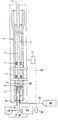
- FIG. 1 shows the side view of a gun barrel to be hardened in connection with a laser system and a program-controlled groove drawing machine.
- 1 designates the weapon barrel, which is aligned on the groove-pulling machine 2 and is fixed.
- the pull rod 3 of the grooving machine extends within the weapon barrel 1 along the soul axis 4 and is supported on the inner surface 5 of the barrel 1 over two guide bushings 6 and 7.
- a laser head 10 is arranged at the end 9 of the pull rod 3, which via an optical fiber 11 with an Nd: YAG laser 12 (e.g. with 2 kW output power).
- the laser head 10 is via a first hose line 13 with a cooling device 14 and a second Hose line 15 with a protective gas source 16 (e.g. with Argon-filled gas bottle).
- the laser head 10 essentially comprises a facet mirror 17, the laser beam coming from the optical fiber 11 on the inner surface 5 of the weapon barrel 1 to be hardened focused, and that due to the occurring in operation enormous heat generation by a coolant, which over the hose line 13 is supplied, can be cooled.
- the laser head 10 is also with a second tube or Hose line 15 connected via a protective gas during transformation hardening on the heated surface of the barrel flows and a deteriorating surface quality Prevents oxide layer formation.
- both drawn gun barrels as well as gun barrels with a smooth barrel profile transformation hardening are drawn gun barrels as well as gun barrels with a smooth barrel profile transformation hardening.
- steel pipes go down to a depth of 0.4 to 0.8 mm let transformation hardening, the hardened surface areas had between 600 and 750 HV.
- the invention comprises Device an electronic control device 18 with which the laser power is regulated and which one on the laser 12 downstream closure unit 19 acts and the correct operation of the laser system constantly monitored such that in the event of a defect, e.g. at a fiber break in the optical fiber or an interrupted one or insufficient cooling of the facet mirror etc., the The gun barrel interrupts the hardening process.
- a defect e.g. at a fiber break in the optical fiber or an interrupted one or insufficient cooling of the facet mirror etc.
- control device 18 is preferred connected to the control device 21 for the groove drawing machine.
- this makes the flexible design of Machining cycles and on the other hand the monitoring of safety-related interlocks guaranteed.
- a third pipe or hose line is provided be through the compressed air or nitrogen across the jet outlet of the laser head is passed through this directed gas flow, the mirror optics and the interior protect the laser head from dirt.
Landscapes
- Chemical & Material Sciences (AREA)
- Engineering & Computer Science (AREA)
- Physics & Mathematics (AREA)
- Thermal Sciences (AREA)
- Crystallography & Structural Chemistry (AREA)
- Mechanical Engineering (AREA)
- Materials Engineering (AREA)
- Metallurgy (AREA)
- Organic Chemistry (AREA)
- Laser Beam Processing (AREA)
- Heat Treatment Of Articles (AREA)
- Conveying And Assembling Of Building Elements In Situ (AREA)
Description
- 1
- Waffenrohr
- 2
- Nutenziehmaschine
- 3
- Ziehstange
- 4
- Seelenachse
- 5
- Oberfläche
- 6,7
- Führungsbuchsen
- 8
- mündungsseitige Ende
- 9
- Ende (Ziehstange)
- 10
- Laserkopf
- 11
- Lichtleitfaser
- 12
- Laser
- 13
- erste Schlauchleitung
- 14
- Kühlvorrichtung
- 15
- zweite Schlauchleitung
- 16
- Schutzgasquelle
- 17
- Facettenspiegel, Strahlumlenkoptik
- 18
- elektronische Steuervorrichtung
- 19
- Verschlußeinheit
- 20
- gestrichelte Linie
- 21
- Steuervorrichtung (Nutenziehmaschine)
Claims (6)
- Vorrichtung zum Härten der Innenkontur eines Waffenrohres (1) mit Laserstrahlung, mit den Merkmalen:a) die Vorrichtung umfaßt einen Laser (12) und einen entlang der Seelenachse (4) des Waffenrohres (1) verschiebbar anordbaren und eine Strahlumlenkoptik (17) enthaltenden Laserkopf (10), so daß die Laserstrahlung mündungsseitig in das Waffenrohr (1) einkoppelbar und mittels der Strahlumlenkoptik (17) senkrecht auf die innere Oberfläche (5) des Waffenrohres (1) führbar ist,b) bei dem Laser (12) handelt es sich um einen Nd:YAG-Laser;c) der Laser (12) ist mit dem Laserkopf (10) über eine Lichtleitfaser (11) verbunden;d) der Laserkopf (10) ist an dem mündungsseitigen Ende (8) einer im Waffenrohr (1) zentrierbaren und in Richtung der Seelenachse (4) des Waffenrohres (1) verschiebbaren Ziehstange (3) befestigt.e) bei der Ziehstange (3) handelt es sich um die Ziehstange einer programmgesteuerten Nutenziehmaschine (2).
- Vorrichtung nach Anspruch 1, dadurch gekennzeichnet, daß es sich bei der Strahlumlenkoptik (17) des Laserkopfes (10) um einen Facettenspiegel handelt, der die Laserstrahlung auf die innere Oberfläche (5) des Waffenrohres (1) fokussiert.
- Vorrichtung nach Anspruch 1 oder 2, dadurch gekennzeichnet, daß der Laserkopf (10) zur Kühlung der Strahlumlenkoptik (17) über eine mündungsseitig aus dem Waffenrohr (1) führbare Rohr- oder Schlauchleitung (13) mit einer Kühlvorrichtung (14) verbunden ist.
- Vorrichtung nach einem der Ansprüche 1 bis 3, dadurch gekennzeichnet, daß der Laserkopf (10) über eine mündungsseitig aus dem Waffenrohr (1) führbare Rohr- oder Schlauchleitung (15) mit einer Schutzgasquelle (16) verbunden ist, und daß der Laserkopf (10) derart ausgebildet ist, daß das Schutzgas bei der Laserbestrahlung der inneren Oberfläche (5) des Waffenrohres (1) auf diese Oberfläche (5) strömt.
- Vorrichtung nach einem der Ansprüche 1 bis 4, dadurch gekennzeichnet, daß eine dritte Rohr- oder Schlauchleitung vorgesehen ist, durch die Druckluft oder Stickstoff führbar ist und deren Austrittsöffnung derart gewählt ist, daß das Gas quer zur Strahlaustrittsöffnung des Laserkopfes (10) austritt, um die Strahlumlenkoptik (17) und den Innenraum des Laserkopfes (10) vor Verschmutzungen zu schützen.
- Vorrichtung nach einem der Ansprüche 1 bis 5, dadurch gekennzeichnet, daß eine elektronische Steuervorrichtung (18) vorgesehen ist, die die Laserleistung regelt und auf eine dem Laser (12) nachgeschaltete Verschlußeinheit (19) wirkt, derart, daß im Falle eines Defektes der Vorrichtung (Faserbruch, keine Kühlung etc) der Härtungsvorgang des Waffenrohres (1) unterbrochen wird.
Applications Claiming Priority (2)
| Application Number | Priority Date | Filing Date | Title |
|---|---|---|---|
| DE19741028A DE19741028C1 (de) | 1997-09-18 | 1997-09-18 | Vorrichtung zum Härten der Innenkontur eines Waffenrohres mit Laserstrahlung |
| DE19741028 | 1997-09-18 |
Publications (2)
| Publication Number | Publication Date |
|---|---|
| EP0908264A1 EP0908264A1 (de) | 1999-04-14 |
| EP0908264B1 true EP0908264B1 (de) | 2001-11-21 |
Family
ID=7842721
Family Applications (1)
| Application Number | Title | Priority Date | Filing Date |
|---|---|---|---|
| EP98116447A Expired - Lifetime EP0908264B1 (de) | 1997-09-18 | 1998-08-31 | Vorrichtung zum Härten der Innenkontur eines Waffenrohres mit Laserstrahlung |
Country Status (5)
| Country | Link |
|---|---|
| US (1) | US6040551A (de) |
| EP (1) | EP0908264B1 (de) |
| DE (2) | DE19741028C1 (de) |
| ES (1) | ES2166124T3 (de) |
| TR (1) | TR199801848A2 (de) |
Families Citing this family (9)
| Publication number | Priority date | Publication date | Assignee | Title |
|---|---|---|---|---|
| DE19853293A1 (de) * | 1998-11-19 | 2000-05-25 | Rheinmetall W & M Gmbh | Verfahren zur Herstellung eines innenseitig mit einer Hartchromschicht versehenen Waffenrohres |
| DE19919688A1 (de) | 1999-04-30 | 2000-11-02 | Rheinmetall W & M Gmbh | Verfahren zur Innenbeschichtung eines Waffenrohres |
| DE10122663C1 (de) * | 2001-05-10 | 2002-08-01 | Heckler & Koch Gmbh | Verfahren zum Endbearbeiten einer Verriegelungsfläche einer Selbstlade-Handfeuerwaffe sowie hierdurch erhaltene Verriegelunsfläche |
| DE10260345B3 (de) * | 2002-12-20 | 2004-09-09 | Siemens Ag | Vorrichtung und Verfahren zum Bearbeiten einer Innenwand einer in ein Werkstück eingebrachten Ausnehmung |
| DE10328450A1 (de) * | 2003-06-25 | 2005-01-20 | Rheinmetall W & M Gmbh | Verfahren zur Beseitigung von Beschichtungs- und/oder Erosionsschäden |
| US20050279741A1 (en) * | 2004-06-17 | 2005-12-22 | Arenberg Jonathan W | Laser burn through sensor |
| DE102005043924B3 (de) * | 2005-09-14 | 2007-04-05 | Heckler & Koch Gmbh | Reflektoranordnung und Verfahren zum Härten von Innenflächen |
| US7897265B2 (en) * | 2006-01-26 | 2011-03-01 | Hamilton Sundstrand Corporation | Low cost, environmentally favorable, chromium plate replacement coating for improved wear performance |
| US8405007B2 (en) * | 2007-01-19 | 2013-03-26 | Beru Aktiengesellschaft | Device for producing a temperature gradient |
Family Cites Families (12)
| Publication number | Priority date | Publication date | Assignee | Title |
|---|---|---|---|---|
| DE364366C (de) * | 1914-02-19 | 1923-03-21 | Robert Kiesswetter | Spaten fuer Bodenbearbeitungsmaschinen |
| DE406043C (de) * | 1921-08-27 | 1924-11-13 | Klaere Stinnes Geb Wagenknecht | Verfahren zum Gerben von tierischen Haeuten |
| US3772496A (en) * | 1971-10-26 | 1973-11-13 | Western Electric Co | Methods of forming a conductive path using an oxygen plasma to reduce reflectivity prior to laser machining |
| FR2637829A1 (fr) * | 1988-10-14 | 1990-04-20 | Framatome Sa | Procede de dispositif de soudage a distance d'un manchon dans un tube notamment dans un generateur de vapeur de centrale nucleaire |
| FR2649923B1 (fr) * | 1989-06-28 | 1992-04-24 | Framatome Sa | Outillage de travail a l'interieur d'un element tubulaire |
| FR2649030B1 (fr) * | 1989-06-28 | 1992-04-24 | Framatome Sa | Dispositif de soudage au laser a l'interieur d'un element tubulaire |
| US5160556A (en) * | 1990-08-22 | 1992-11-03 | United Container Machinery Group, Inc. | Method of hardening corrugating rolls |
| US5262613A (en) * | 1991-09-24 | 1993-11-16 | General Laser, Inc. | Laser retrofit for mechanical engravers |
| JP3214074B2 (ja) * | 1992-07-15 | 2001-10-02 | 石川島播磨重工業株式会社 | レーザ照射用トーチ |
| DE4241592C1 (de) * | 1992-12-10 | 1993-11-04 | Daimler Benz Ag | Anordnung zur veraenderung der geometrischen gestalt eines lichtbuendels mit spiegeln |
| DE19544824C2 (de) * | 1995-08-23 | 1998-06-04 | Rheinmetall Ind Ag | Gezogenes Waffenrohr und Verfahren zur Herstellung eines derartigen Rohres |
| US5719373A (en) * | 1996-11-18 | 1998-02-17 | Ingersoll-Rand Company | Laser device for heating a surface formed by a small diameter bore in a workpiece |
-
1997
- 1997-09-18 DE DE19741028A patent/DE19741028C1/de not_active Expired - Fee Related
-
1998
- 1998-08-31 DE DE59802695T patent/DE59802695D1/de not_active Expired - Fee Related
- 1998-08-31 ES ES98116447T patent/ES2166124T3/es not_active Expired - Lifetime
- 1998-08-31 EP EP98116447A patent/EP0908264B1/de not_active Expired - Lifetime
- 1998-09-17 TR TR1998/01848A patent/TR199801848A2/xx unknown
- 1998-09-18 US US09/156,501 patent/US6040551A/en not_active Expired - Lifetime
Also Published As
| Publication number | Publication date |
|---|---|
| TR199801848A3 (tr) | 1999-04-21 |
| DE59802695D1 (de) | 2002-02-21 |
| EP0908264A1 (de) | 1999-04-14 |
| ES2166124T3 (es) | 2002-04-01 |
| DE19741028C1 (de) | 1998-11-05 |
| TR199801848A2 (xx) | 1999-04-21 |
| US6040551A (en) | 2000-03-21 |
Similar Documents
| Publication | Publication Date | Title |
|---|---|---|
| DE60220343T2 (de) | Schweissvorrichtung mit einem miniaturisierten Laserstrahl | |
| DE69612411T2 (de) | Unterwasserbehandlungsverfahren und -system | |
| EP2429755B1 (de) | Vorrichtung und verfahren zur umfangsbearbeitung eines materialstranges mittels laser | |
| EP0762947A1 (de) | Vorrichtung zur materialbearbeitung mit einem laser | |
| EP0543830B1 (de) | Vorrichtung und verfahren zum laserschweissen eines rohres | |
| DE19607327A1 (de) | Laserstrahlmaschinen | |
| EP0458180B1 (de) | Verfahren und Vorrichtung zum Laserstrahlschneiden | |
| DE19741028C1 (de) | Vorrichtung zum Härten der Innenkontur eines Waffenrohres mit Laserstrahlung | |
| DE202018107281U1 (de) | Strahlformungseinheit mit Kühlsystem für Hochleistungslaser | |
| DE102018208752B4 (de) | Vorrichtung und Verfahren zur Bearbeitung zur Bearbeitung schwer zugänglicher Werkstücke sowie Verwendung einer Vorrichtung | |
| DE69009366T2 (de) | Gerät und Verfahren zum Schweissen von Werkstücken mittels eines Laserstrahls. | |
| EP1247878B1 (de) | Gerät zur Laser-Pulverbeschichtung | |
| DE69004412T2 (de) | Laser-Arbeitsverfahren innerhalb eines Rohres und Arbeitskopf zur Durchführung des Verfahrens. | |
| EP1127652B1 (de) | Verfahren und Vorrichtung zum Bearbeiten einer Innenfläche einer zylinderförmigen Bohrung mittels Laser und gekühlter Umlenkoptik | |
| EP0543829B1 (de) | Vorrichtung und verfahren zum laserschweissen eines rohres | |
| DE102022112050A1 (de) | Düse für die Laserbearbeitung mit hohen Fokuslagen | |
| DE102006034031B4 (de) | Luftgekühltes Steckerbauteil für einen Lichtwellenleiter | |
| EP4031319A1 (de) | Werkstoffzuführungsvorrichtung | |
| EP1464436B1 (de) | Werkzeug zur Feinbearbeitung mit Laserstrahl der Oberfläche einer Bohrung | |
| DE102021103603B4 (de) | Verfahren zum Bearbeiten einer optischen Faser, optische Faser sowie Kopplungsanordnung | |
| DE102009018915A1 (de) | Mehrstrahllaserbearbeitungskopf | |
| DE102005043924B3 (de) | Reflektoranordnung und Verfahren zum Härten von Innenflächen | |
| EP1702498A1 (de) | Verfahren zur erwärmung von bauteilen | |
| DE102024209106A1 (de) | Schweißdüse, Verfahren zur Herstellung der Schweißdüse und Verfahren zur Auftragsschweißung | |
| DE10248278A1 (de) | Verfahren und Vorrichtung zum Bearbeiten einer Oberfläche |
Legal Events
| Date | Code | Title | Description |
|---|---|---|---|
| PUAI | Public reference made under article 153(3) epc to a published international application that has entered the european phase |
Free format text: ORIGINAL CODE: 0009012 |
|
| 17P | Request for examination filed |
Effective date: 19990114 |
|
| AK | Designated contracting states |
Kind code of ref document: A1 Designated state(s): CH DE ES FR GB IT LI SE |
|
| AX | Request for extension of the european patent |
Free format text: AL;LT;LV;MK;RO;SI |
|
| 17Q | First examination report despatched |
Effective date: 19990827 |
|
| AKX | Designation fees paid |
Free format text: CH DE ES FR GB IT LI SE |
|
| GRAG | Despatch of communication of intention to grant |
Free format text: ORIGINAL CODE: EPIDOS AGRA |
|
| GRAG | Despatch of communication of intention to grant |
Free format text: ORIGINAL CODE: EPIDOS AGRA |
|
| GRAH | Despatch of communication of intention to grant a patent |
Free format text: ORIGINAL CODE: EPIDOS IGRA |
|
| ITF | It: translation for a ep patent filed | ||
| GRAH | Despatch of communication of intention to grant a patent |
Free format text: ORIGINAL CODE: EPIDOS IGRA |
|
| GRAA | (expected) grant |
Free format text: ORIGINAL CODE: 0009210 |
|
| AK | Designated contracting states |
Kind code of ref document: B1 Designated state(s): CH DE ES FR GB IT LI SE |
|
| REG | Reference to a national code |
Ref country code: CH Ref legal event code: NV Representative=s name: E. BLUM & CO. PATENTANWAELTE Ref country code: CH Ref legal event code: EP |
|
| REG | Reference to a national code |
Ref country code: GB Ref legal event code: IF02 |
|
| ET | Fr: translation filed | ||
| REF | Corresponds to: |
Ref document number: 59802695 Country of ref document: DE Date of ref document: 20020221 |
|
| GBT | Gb: translation of ep patent filed (gb section 77(6)(a)/1977) |
Effective date: 20020208 |
|
| REG | Reference to a national code |
Ref country code: ES Ref legal event code: FG2A Ref document number: 2166124 Country of ref document: ES Kind code of ref document: T3 |
|
| PLBE | No opposition filed within time limit |
Free format text: ORIGINAL CODE: 0009261 |
|
| STAA | Information on the status of an ep patent application or granted ep patent |
Free format text: STATUS: NO OPPOSITION FILED WITHIN TIME LIMIT |
|
| 26N | No opposition filed | ||
| PGFP | Annual fee paid to national office [announced via postgrant information from national office to epo] |
Ref country code: DE Payment date: 20030805 Year of fee payment: 6 |
|
| PG25 | Lapsed in a contracting state [announced via postgrant information from national office to epo] |
Ref country code: DE Free format text: LAPSE BECAUSE OF NON-PAYMENT OF DUE FEES Effective date: 20050301 |
|
| REG | Reference to a national code |
Ref country code: CH Ref legal event code: PFA Owner name: RHEINMETALL W & M GMBH Free format text: RHEINMETALL W & M GMBH#HEINRICH-EHRHARDT-STRASSE 2#29345 UNTERLUESS (DE) -TRANSFER TO- RHEINMETALL W & M GMBH#HEINRICH-EHRHARDT-STRASSE 2#29345 UNTERLUESS (DE) |
|
| REG | Reference to a national code |
Ref country code: FR Ref legal event code: PLFP Year of fee payment: 18 |
|
| PGFP | Annual fee paid to national office [announced via postgrant information from national office to epo] |
Ref country code: GB Payment date: 20150819 Year of fee payment: 18 Ref country code: ES Payment date: 20150827 Year of fee payment: 18 Ref country code: CH Payment date: 20150819 Year of fee payment: 18 |
|
| PGFP | Annual fee paid to national office [announced via postgrant information from national office to epo] |
Ref country code: FR Payment date: 20150820 Year of fee payment: 18 Ref country code: SE Payment date: 20150819 Year of fee payment: 18 |
|
| PGFP | Annual fee paid to national office [announced via postgrant information from national office to epo] |
Ref country code: IT Payment date: 20150824 Year of fee payment: 18 |
|
| REG | Reference to a national code |
Ref country code: CH Ref legal event code: PL |
|
| GBPC | Gb: european patent ceased through non-payment of renewal fee |
Effective date: 20160831 |
|
| PG25 | Lapsed in a contracting state [announced via postgrant information from national office to epo] |
Ref country code: SE Free format text: LAPSE BECAUSE OF NON-PAYMENT OF DUE FEES Effective date: 20160901 Ref country code: CH Free format text: LAPSE BECAUSE OF NON-PAYMENT OF DUE FEES Effective date: 20160831 Ref country code: LI Free format text: LAPSE BECAUSE OF NON-PAYMENT OF DUE FEES Effective date: 20160831 |
|
| REG | Reference to a national code |
Ref country code: SE Ref legal event code: EUG |
|
| REG | Reference to a national code |
Ref country code: FR Ref legal event code: ST Effective date: 20170428 |
|
| PG25 | Lapsed in a contracting state [announced via postgrant information from national office to epo] |
Ref country code: GB Free format text: LAPSE BECAUSE OF NON-PAYMENT OF DUE FEES Effective date: 20160831 Ref country code: FR Free format text: LAPSE BECAUSE OF NON-PAYMENT OF DUE FEES Effective date: 20160831 |
|
| PG25 | Lapsed in a contracting state [announced via postgrant information from national office to epo] |
Ref country code: IT Free format text: LAPSE BECAUSE OF NON-PAYMENT OF DUE FEES Effective date: 20160831 |
|
| PG25 | Lapsed in a contracting state [announced via postgrant information from national office to epo] |
Ref country code: ES Free format text: LAPSE BECAUSE OF NON-PAYMENT OF DUE FEES Effective date: 20160831 |
|
| REG | Reference to a national code |
Ref country code: ES Ref legal event code: FD2A Effective date: 20181116 |
|
| PG25 | Lapsed in a contracting state [announced via postgrant information from national office to epo] |
Ref country code: ES Free format text: LAPSE BECAUSE OF NON-PAYMENT OF DUE FEES Effective date: 20160901 |