EP0908089A1 - Ballendichteregeleinrichtung für Ballenpresse - Google Patents
Ballendichteregeleinrichtung für Ballenpresse Download PDFInfo
- Publication number
- EP0908089A1 EP0908089A1 EP98203318A EP98203318A EP0908089A1 EP 0908089 A1 EP0908089 A1 EP 0908089A1 EP 98203318 A EP98203318 A EP 98203318A EP 98203318 A EP98203318 A EP 98203318A EP 0908089 A1 EP0908089 A1 EP 0908089A1
- Authority
- EP
- European Patent Office
- Prior art keywords
- crop material
- baling chamber
- charge
- control system
- density control
- Prior art date
- Legal status (The legal status is an assumption and is not a legal conclusion. Google has not performed a legal analysis and makes no representation as to the accuracy of the status listed.)
- Granted
Links
- 239000000463 material Substances 0.000 claims abstract description 82
- 230000006835 compression Effects 0.000 claims abstract description 13
- 238000007906 compression Methods 0.000 claims abstract description 13
- 230000004044 response Effects 0.000 claims description 13
- 238000000034 method Methods 0.000 claims description 11
- 238000012544 monitoring process Methods 0.000 claims description 7
- 239000010720 hydraulic oil Substances 0.000 abstract description 2
- 239000003921 oil Substances 0.000 description 39
- 241000282472 Canis lupus familiaris Species 0.000 description 34
- 230000007246 mechanism Effects 0.000 description 13
- 230000000712 assembly Effects 0.000 description 8
- 238000000429 assembly Methods 0.000 description 8
- 230000009471 action Effects 0.000 description 5
- 230000001276 controlling effect Effects 0.000 description 3
- 230000000694 effects Effects 0.000 description 3
- 239000010902 straw Substances 0.000 description 3
- 238000006243 chemical reaction Methods 0.000 description 2
- 210000000707 wrist Anatomy 0.000 description 2
- 244000025254 Cannabis sativa Species 0.000 description 1
- 230000001154 acute effect Effects 0.000 description 1
- 230000003321 amplification Effects 0.000 description 1
- 230000008901 benefit Effects 0.000 description 1
- 230000005540 biological transmission Effects 0.000 description 1
- 230000000903 blocking effect Effects 0.000 description 1
- 230000008859 change Effects 0.000 description 1
- 238000011109 contamination Methods 0.000 description 1
- 230000010485 coping Effects 0.000 description 1
- 230000008878 coupling Effects 0.000 description 1
- 238000010168 coupling process Methods 0.000 description 1
- 238000005859 coupling reaction Methods 0.000 description 1
- 238000010586 diagram Methods 0.000 description 1
- 230000006870 function Effects 0.000 description 1
- 239000004463 hay Substances 0.000 description 1
- 208000015181 infectious disease Diseases 0.000 description 1
- 238000003780 insertion Methods 0.000 description 1
- 230000037431 insertion Effects 0.000 description 1
- 238000003199 nucleic acid amplification method Methods 0.000 description 1
- 230000003287 optical effect Effects 0.000 description 1
- 239000002245 particle Substances 0.000 description 1
- 230000000737 periodic effect Effects 0.000 description 1
- 230000009467 reduction Effects 0.000 description 1
- 230000000284 resting effect Effects 0.000 description 1
- 230000002441 reversible effect Effects 0.000 description 1
- 230000000630 rising effect Effects 0.000 description 1
- 239000004460 silage Substances 0.000 description 1
Images


Classifications
-
- A—HUMAN NECESSITIES
- A01—AGRICULTURE; FORESTRY; ANIMAL HUSBANDRY; HUNTING; TRAPPING; FISHING
- A01F—PROCESSING OF HARVESTED PRODUCE; HAY OR STRAW PRESSES; DEVICES FOR STORING AGRICULTURAL OR HORTICULTURAL PRODUCE
- A01F15/00—Baling presses for straw, hay or the like
- A01F15/08—Details
- A01F15/0825—Regulating or controlling density or shape of the bale
Definitions
- the present invention relates generally to an apparatus and a method for controlling the density of packages of crop material formed in the baling chamber of an agricultural baler, and more particularly, to an apparatus and a method involving means for sensing the force applied on said packages and means for sensing the introduction of new charges of crop material into this baling chamber.
- the invention has particular application to the interruption of the normal operation of the density control system under conditions when no charges of crop material are fed into the baler, as on headlands or when the baler is halted on the field.
- Conventional agricultural balers comprise a frame which is travelled on a pair of wheels over a field for picking up therefrom hay, straw or silage grass and feeding such crop material to a baling chamber in which it is compressed to parallelepiped packages under action of a plunger which reciprocates inside the baling chamber.
- a tying mechanism is operated to encircle the completed package with a plurality of strands and to knot the strands ends together to form a finished bale which will be ejected out of the baler.
- the baling chamber comprises at least one movable wall section whereof the position can be adjusted to modify the transverse cross section of the baling chamber and thereby vary the resistance met by the reciprocating plunger when a new charge of crop material is introduced into the chamber and thrust against the package. It is well known in the art to equip the movable wall section with actuator means to automatically adjust its position in response to load sensor means sensing the actual force by which the material in the baling chamber is compressed in order to adjust the density of the package to a predetermined value.
- the restricted chamber may cause such resistance to the movement of the package that the blow of the plunger on this charge effects unacceptable stress on the structure and ruptures part of the baling mechanism.
- Important damage to the baler may be precluded by providing the drive line of the plunger with shear bolts which break and disconnect the plunger from the tractor drive line whenever such extraordinary forces are encountered.
- shear bolts are satisfactory for dealing with unforeseeable force peaks, but they will only cause frustration when used for coping with the more frequent effects of force amplification on or after turning the baler on headlands.
- the normal operation of the bale density control system may be interrupted by a control valve which is operated by the stuffer mechanism.
- the valve precludes that pressurized oil is fed to the hydraulic actuator of the movable wall portion.
- Such system only works satisfactorily in balers having a stuffer mechanism which is operated in response to a complete filling of the feeder duct. Otherwise the system would not distinguish between conditions wherein new charges are introduced into the baling chambers and others wherein the stuffer mechanism is working idly. It requires a reliable sensor for assessing a complete filling of the duct further in order to preclude inopportune adjustment of the baling chamber.
- a density control system for an agricultural baler which comprises:
- Said density control system is characterized in that said charge sensing means are operable to sense the passage of a newly introduced charge of crop material along at least one wall portion of said baling chamber.
- control system can distinguish between peak loads caused by the impact of the plunger on a new charge of crop material and peak loads caused by the impact on an expanding face of the package in the baling chamber. Only in the first case an adjustment of the cross section of the baling chamber may be required.
- the load sensing means may be associated with the drive line of the plunger to measure the force applied by the plunger on the package, or with a wall of the baling chamber in order to measure the force applied by the package on this wall.
- the control system may comprise means for precluding actuation of the actuator means when no passage of a new charge of crop material has been sensed. In this manner it is prevented that the cross section of the baling chamber is changed in response to the peak loads which occur when the plunger hits the expanding face of a crop package in the baling chamber.
- these precluding means may be operable to preclude any movement of the movable wall section. Such system stabilizes the baling chamber while the baler is running idle on the headlands and prevents that the low forces encountered by the plunger engender an unwanted restriction of the section of the baling chamber.
- the precluding means may enable the control of the actuator means in response to the output of load sensing means for a fixed time interval.
- Further means may be provided for enabling an increase in density of the package under conditions that said charge sensing means have sensed a new introduction of crop material into the baling chamber.
- These means may comprise a hydraulic control valve providing pressurized oil to another control valve which is connected to a hydraulic cylinder which positions the movable wall section.
- the charge sensing means sense the movement of a pivotable member, such as a hay dog, which extends through a wall portion of the baling chamber.
- a method for controlling the density of packages of crop material in an agricultural baler which comprises:
- FIG. 1 shows an agricultural baler 10 comprising a frame 11 which is equipped with a forwardly extending tongue 12 provided at its front end with hitch means (not shown) for coupling the baler 10 to a towing tractor.
- a pick-up assembly 14 lifts windrowed crop material off the field as the baler 10 is travelled thereover and delivers such material into the front end of a rearwardly and upwardly curved, charge-forming feeder duct 16.
- the duct 16 communicates at its upper end with an overhead, fore-and-aft extending baling chamber 18 into which crop charges are loaded by a cyclically operating stuffer mechanism 20.
- a continuously operating packer mechanism 22 at the lower front end of the feeder duct 16 continuously feeds and packs material into the duct 16 as to cause charges of the crop material to take on and assume the internal configuration of the duct 16 prior to periodic engagement by the stuffer 20 and insertion up into the baling chamber 18.
- the feeder duct 16 may be equipped with means (not shown) for establishing whether a complete charge has been formed therein and operating the stuffer 20 in response thereto. Each action of the stuffer 20 introduces a "charge” or "flake” of crop material from the duct 16 into the chamber 18.
- a plunger 24 reciprocates in a fore-and-aft direction within the baling chamber 18 under action of a pair of pitman rods 25 which are linked to the crank arms 26 of a gearbox 27 driven by a transmission shaft 29 which is connected to the PTO shaft of the tractor.
- the reciprocating plunger 24 pushes each new charge introduced into the baling chamber 18 rearwardly and forms the subsequent charges into a package of crop material, which is forced by the same action of the plunger 24 toward a rearmost discharge aperture 28 of the chamber.
- the baling chamber 18 comprises at least one movable wall portion 30 of which the position can be adjusted to vary the cross section of the aperture 28. Reduction of this cross section will increase the resistance to rearward movement of the crop packages and hence increase the density of the crop material contained therein. Similarly an enlargement of the cross section will reduce said resistance to rearward movement and hence equally reduce the density of the newly formed packages.
- the position of the wall portion 30 is controlled by actuator means comprising of a pair of hydraulic cylinders 31 (only one shown in Figure 1) which are installed between the frame 11 and the wall portion 30.
- each package is securely bound in its final compacted form by a tying mechanism 32 .
- the length of each bale produced by the baler 10 can be adjustably predetermined by conventional means not shown.
- the tying mechanism 32 comprises a series of periodically actuated needles 33 which are normally stationed in a stand-by condition below the chamber 18 but which, when actuated, swing upwardly through and across the baling chamber 18 to present twine to a corresponding series of knotters positioned on top of the chamber 18 and extending across the width of the latter.
- the baling chamber 18 comprises a pair of side walls 36, a top wall 37 and a bottom wall 38.
- the side walls 36 are provided with a longitudinal slot 40 for receiving therein the bearings 41 which support the plunger 24 during its reciprocation inside the baling chamber 18.
- the top wall 37 and bottom wall 38 are equally slotted to permit passage of the needles 33 and the twine therethrough during each tying cycle.
- the retaining means comprise a pair of hay dog assemblies 44 mounted to each side wall 36 and a set of similar hay dog assemblies 45 mounted to the top wall 37.
- Each hay dog assembly 44 comprises a so-called hay dog 47 constituted by a pivotable member extending through a longitudinal slot in one of the side walls 36. As shown in Figure 3, the hay dog 47 is mounted for pivotment about the shaft of vertical bolt 48 which is mounted through a pair of lugs 50 welded to the outside of the side wall 36.
- the hay dog 47 has a forward edge 53 extending at an acute angle from the wall 36 and a rearward edge 54 extending at a substantially right angle from the wall 36 when the hay dog 47 is in its rest position shown in Figure 3.
- the hay dog assemblies 44 are mounted at such distance from the gearbox 27 that the rearward edges 54 of the hay dogs 47 are positioned in alignment with or slightly in front of the rearwardmost position of the plunger 24 during its compression stroke.
- the hay dogs 47 are received in a series of longitudinal slits 56 in the sides of the plunger body such that they are not engaged by the plunger 47 itself during each stroke of the plunger mechanism. Consequently, when no fresh crop material is introduced into the baling chamber 18 and the baler is running idle, the hay dogs 47 remain in their inward position shown in Figure 3.
- the stuffer mechanism 20 introduces a new charge of crop material into the baling chamber 18, it will be engaged by the plunger 24 and shoved rearwardly along the hay dogs 47.
- the crop material slides along the forward edge 53 of the hay dogs 47 and pushes the latter outwardly.
- the action of the springs 51 brings the hay dogs 47 back to their rest positions.
- the plunger 24 retracts and starts travelling forwardly again, the compressed package of crop material tends to dilate and its front face expands in the direction of the plunger.
- the material is held back by the rear edges 54 of the hay dogs 47 on both sides of the baling chamber. Consequently the front face of the package is stabilized and the inlet opening in the bottom wall 38 will not be obturated thereby, such that further charges of crop material may be introduced into the baling chamber 18 without any hindrance thereto.
- the hay dog assemblies 45 in the top wall 37 are similar in structure and operation and do therefore not require a further detailed description.
- the movement of the hay dog assemblies 44, 45 is indicative of an introduction of a fresh charge of crop material into the baling chamber 18.
- This movement is sensed by means including a switch 60, which is mounted to a vertical support plate 61 welded above the hay dog assembly 44 to one of the side walls 36 ( Figure 3).
- the switch 60 comprises a pivotable member 62 which is engaged by the hay dog 47 when the latter is pushed outwardly by a new charge passing along this portion of the side wall 36.
- the magnitude of the force by which the crop material is compressed is measured by a load sensor 75 which is installed inbetween the plunger gearbox 27 and the baler frame 11.
- the reaction forces from the package in the baling chamber 18 are transmitted via the plunger 24, the pitman rods 25 and the crank arms 26 upon the gearbox 27 whereof the lower portion is bolted onto the frame 11.
- the reaction force at the top of the gearbox 27 is measured by the load sensor 75 which hence provides an output signal proportional to the plunger forces.
- load sensor 75 may be of the type described in EP-A-0,389,322.
- the plunger load may also be established by a pair of wrist pins 76 which connect the rods 25 to the body of the plunger 24.
- Such pins 76 may be hollow and equipped with shear stress sensors such a strain gauges for measuring the load on the plunger 24, as described in EP-A-0,223,350.
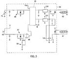
- the density control system comprises hydraulic circuitry in accordance with Figure 4.
- a continuously operated gear pump 78 takes hydraulic oil via a filter 79 from an oil tank 80.
- the oil is fed via a pressure line 81 to a solenoid-operated by-pass valve 82.
- this valve When this valve is in its rest position as shown in Figures 4 and 5, the oil is drained back to the oil tank 80 via a return line 83 which is provided with an orifice 84 which has a slight pressurizing effect on the oil in the return line 83.
- the oil from the pump 78 can no longer escape via the return line 83 and pressurized oil is supplied via a non-return valve 86 and a further pressure line 85 to an inlet port of a solenoid-operated density control valve 87.
- the corresponding outlet port is connected to a supply line 89 equipped with a manometer 88 for displaying the oil pressure in the density control circuit.
- the supply line 89 is linked to the rod ends of the hydraulic cylinders 31 which control the position of the movable wall portion 30.
- the control valve 87 links the pressure line 85 and the supply line 89 to a return line 90 which is connected to the return line 83.
- the oil pressure in the pressure line 85 is limited by a pressure relief valve 91.
- the signals from the hay dog switch 60 and the load sensor 75 or 76 are used in the density control system, which further comprises a circuit board 94 ( Figure 5) for analyzing these baler signals and energizing or deenergizing the solenoids of the by-pass valve 82 and the control valve 87 in response thereto.
- the circuit board 94 includes a microprocessor 95, for example of the Microchip type PIC16C73, which is provided with erasable memory means into which a program can be loaded in accordance with the description given hereafter.
- the output of the load sensor 75 is linked via a diode protected resistor circuit 96 to an analogous input pin of the microprocessor 95.
- the hay dog switch 60 is connected via another diode protected resistor circuit 97 to the positive input pin of a comparator 98.
- a voltage divider 99 provides a reference voltage to the negative input pin of the comparator 98.
- the output pin of the comparator is linked to a digital input gate of the microprocessor 95.
- Two output gates of the microprocessor 95 are connected to the input pins of two of electronic switches 100, 101, such as Smartfets of the type BTS413A.
- the output pin of the switch 100 is connected to the solenoid of the by-pass valve 82.
- the solenoid of the control valve 87 is connected between the voltage source V and a relay 103. At rest this relay connects the solenoid to ground such that the valve 87 is actuated and shifted to the left.
- the relay 103 is controlled by the output of Smartfet 100. When the latter is low, the relay 103 is not actuated and the solenoid of the control valve 87 remains energized.
- the other pin of the relay 103 is connected to the output pin of the Smartfet 101.
- the output pin of the latter is connected to ground and the solenoid of the control valve 87 is energized to keep the valve 87 in its leftmost position.
- the voltage source in is connected to the output pin and the relay 103.
- the valve 87 is deactivated and returns to its rest position shown in Figures 4 and 5.
- the program loaded into the microprocessor 95 screens the input signals from the load sensor 75 and the hay dog switch 60 and provides an output to the Smartfets 100, 101 in accordance with the description following below.
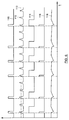
- the microprocessor 95 monitors the input from the hay dog switch 60.
- a graph 110 showing a typical evolution of this input is depicted in Figure 6.
- the switch 60 closes, the voltage provided to the digital input pin of the microprocessor 95 raises from LOW to HIGH.
- the program sets a HIGH to the output pin of the microprocessor 95 for energizing the solenoid of the by-pass valve 82.
- the program resets this output after an interval which is slightly shorter than the cycle time of the plunger 24. This interval may be about 1.2 sec long.
- the output of Smartfet 100 is shown in graph 114 in Figure 6. During this actuation interval pressurized oil is provided to the control valve 87.
- the program After the actuation interval, the program resets the value at the output pin and the by-pass valve 82 is de-energized, thereby ending the further supply of pressurized oil to the control valve 87.
- the microprocessor 95 samples the signal from the load sensor 75 at a rate of 10 KHz.
- the program adds up the results from 10 consecutive samples and calculates their mean value to establish a new load value. Hence this value is updated at a rate of 1 KHz.
- the evolution of the established load values is illustrated by graph 112 in Figure 6.
- the density control program further compares the established plunger load values to a threshold value (dashed line 113) which has been selected by the baler operator. When the mean load value exceeds this threshold value, the program sets the output of the microprocessor 95 to the Smartfet 101 to HIGH in order to connect the output of the latter to the voltage source. In case the Smartfet 100 is energized already by a recent passage of crop material along the hay dog switch 60, the voltage is transferred upon the contact of the density control valve 87. The evolution of the tension at the contact of the valve solenoid is represented by graph 116 in Figure 6.
- valve 87 returns to its rightmost position and oil from the bale chamber cylinders 31 is permitted to flow back to the oil tank 80.
- the resulting evolution of the oil pressure in hydraulic line 89 at the outlet port of the control valve 87 is illustrated by graph 118.
- the by-pass valve 82 and the relay 103 are enabled.
- the load peak detected by sensor 75 de-energizes the control valve 87 and oil is permitted to flow back to the oil tank 80 via orifice 84.
- the pressure in line 85 diminishes gradually, until the value of the measured load falls below the threshold value (113).
- the control valve 87 is reactuated and the pressurized oil is pumped to the cylinders 31.
- the by-pass valve 82 returns to its rest position and no more oil is added to the cylinder line 89.
- the valve 87 remains actuated and the non-return valve 86 closes, thereby blocking the oil in the line 89 and the cylinders 31.
- the pressure in the line 89 remains substantially constant until the next charge of crop material has been fed to the baling chamber 18. However there may still be a small fall of cylinder pressure, following mainly from the relaxation of the crop package in the baling chamber 18.
- Oil is added to the cylinders 31 until, at the end of the fixed interval, the by-pass valve 82 is deactivated and the oil pressure at the inlet port of the control valve 87 drops.
- the non-return valve 86 closes and blocks the oil in the cylinders 31, thereby securing the position of the movable wall portion 30.
- the introduction of a new charge of crop material causes at first an increase in bale chamber section during a first interval, followed by a decrease of the section during a second interval.
- the resulting position of the movable wall portion 30 depends on the ratio between these two time intervals. The higher and wider the load peak sensed by the load sensor 75, the longer the first interval will be and the larger the bale chamber section will be. When the load peak is lower, the first interval will be shorter and more oil will be added to the cylinders 31, causing a decrease of the bale chamber section.
- an equilibrium will be reached in which the amount of oil drained during each compression stroke is equal to the amount of oil added in between the compression strokes.
- the density control system precludes a readjustment of the movable wall portion 30 in response to the loads sensed by the sensor 75: the load controlled steering signal from the Smartfet 101 is interrupted by the relay 103. Furthermore no pressurized oil is available at the inlet port of the control valve 87, as the by-pass valve 82 is not actuated.
- the sensor switch 60 monitors the movement of a hay dog 47 installed above the baling chamber slot 40. This position has the advantage that the risk for contamination of the switch 60 by stray straw or hay particles is substantially less than below the slot 40.
- the mechanical switch 60 may also be replaced with contactless sensors such as proximity switches or optical sensors. It is also conceivable to monitor the movement of another member which has been installed on one portion of a wall of the baling chamber 18 for the sole purpose of establishing the passage of a new charge of crop material therealong and which has no function in retaining the package during the reverse stroke of the plunger 24.
Landscapes
- Life Sciences & Earth Sciences (AREA)
- Environmental Sciences (AREA)
- Harvester Elements (AREA)
Applications Claiming Priority (3)
| Application Number | Priority Date | Filing Date | Title |
|---|---|---|---|
| GB9721106A GB2330110A (en) | 1997-10-07 | 1997-10-07 | Bale density control system for agricultural balers |
| GB9721106 | 1997-10-07 | ||
| US09/165,560 US6026741A (en) | 1997-10-07 | 1998-10-02 | Bale density control system for agricultural balers |
Publications (2)
| Publication Number | Publication Date |
|---|---|
| EP0908089A1 true EP0908089A1 (de) | 1999-04-14 |
| EP0908089B1 EP0908089B1 (de) | 2002-08-28 |
Family
ID=26312368
Family Applications (1)
| Application Number | Title | Priority Date | Filing Date |
|---|---|---|---|
| EP98203318A Expired - Lifetime EP0908089B1 (de) | 1997-10-07 | 1998-10-01 | Ballendichteregeleinrichtung für Ballenpresse |
Country Status (3)
| Country | Link |
|---|---|
| US (1) | US6026741A (de) |
| EP (1) | EP0908089B1 (de) |
| GB (1) | GB2330110A (de) |
Cited By (6)
| Publication number | Priority date | Publication date | Assignee | Title |
|---|---|---|---|---|
| EP2644019A1 (de) * | 2012-03-30 | 2013-10-02 | CNH Belgium N.V. | Reibungsblöcke für eine Quaderballenpresse |
| EP2644018A1 (de) * | 2012-03-30 | 2013-10-02 | CNH Belgium N.V. | Bewegbare Reibungsblöcke für eine Quaderballenpresse |
| WO2014076271A1 (en) * | 2012-11-19 | 2014-05-22 | Cnh Belgium N.V. | Density control system |
| US9913432B2 (en) | 2014-12-18 | 2018-03-13 | Agco Corporation | Square baler providing side-to-side bale uniformity |
| US10201129B2 (en) | 2014-07-30 | 2019-02-12 | Cnh Industrial America Llc | Baler with improved cross member for mounting the gearbox |
| EP3563663A1 (de) * | 2018-05-04 | 2019-11-06 | CNH Industrial Belgium N.V. | Hochdichte kolbenbewegung |
Families Citing this family (21)
| Publication number | Priority date | Publication date | Assignee | Title |
|---|---|---|---|---|
| GB2339719A (en) * | 1998-07-23 | 2000-02-09 | Ford New Holland Nv | Bale discharge means for a rectangular baler |
| GB2351941A (en) * | 1999-07-08 | 2001-01-17 | Ford New Holland Nv | Aensor arrangement for an agricultural baler |
| DE10047336A1 (de) * | 2000-09-23 | 2002-04-11 | Paals Packpressen Fabrik Gmbh | Ballenpresse für loses Preßgut |
| US6370852B1 (en) * | 2000-10-31 | 2002-04-16 | Deere & Company | Arrangement for the storage of data specific to a bale |
| DE10139450A1 (de) * | 2001-08-10 | 2003-05-08 | Deere & Co | Ballenpresse |
| DE10145690A1 (de) * | 2001-08-10 | 2003-03-13 | Deere & Co | Ballenpresse |
| DE10145691A1 (de) * | 2001-08-10 | 2003-03-13 | Deere & Co | Ballenpresse |
| US7024839B2 (en) * | 2001-10-11 | 2006-04-11 | Paul Wingert | Agricultural bagger with upper tunnel compaction and chute agitation |
| US7341000B2 (en) * | 2002-07-05 | 2008-03-11 | Kodak Graphic Communications Canada Company | Slipsheet compactor system |
| US7007599B2 (en) * | 2003-09-17 | 2006-03-07 | Deere & Company | Baler plunger drive load measurement pin offset from either connecting rod center line or horizontal mid-plane of baling chamber |
| US20060168913A1 (en) * | 2005-01-31 | 2006-08-03 | Wingert Paul R | Agricultural bagger with dual rotor and/or variable-taper tunnel |
| BE1019619A3 (nl) * | 2009-09-17 | 2012-09-04 | Cnh Belgium Nv | Een rechthoekige balenpers met een stuureenheid. |
| US9078398B2 (en) * | 2012-05-25 | 2015-07-14 | Deere & Company | Agricultural baler with shape sensors and method |
| US8935979B2 (en) | 2012-12-14 | 2015-01-20 | Cnh Industrial America Llc | Even bale block for monitoring bale shape in a round baler |
| BE1021150B1 (nl) * | 2013-06-03 | 2016-01-13 | Cnh Industrial Belgium Nv | Werkwijze voor het verwerken van belastingssignaal van een balenpers |
| BE1021151B1 (nl) | 2013-06-03 | 2016-01-12 | Cnh Industrial Belgium Nv | Belastingssensor voor een balenpers voor gebruik in de landbouw |
| US10225990B2 (en) * | 2015-07-03 | 2019-03-12 | Cnh Industrial America Llc | Retractable blocks in the doors of a large square baler |
| BE1023943B1 (nl) * | 2016-04-11 | 2017-09-15 | Cnh Industrial Belgium Nv | Rechthoekigebalenpers met verbeterd volpropmechanisme |
| BE1023781B1 (nl) * | 2016-05-18 | 2017-07-24 | Cnh Industrial Belgium Nv | Rechthoekigebalenpers met een verbeterd systeem en een verbeterde regelmethode voor het regelen van de baalvorming |
| US12484484B2 (en) * | 2022-10-18 | 2025-12-02 | Deere & Company | Dynamic resistance generator for square baler |
| CN116508508B (zh) * | 2023-05-15 | 2025-06-10 | 潍柴雷沃智慧农业科技股份有限公司 | 一种方捆打捆机草捆密度控制方法和系统 |
Citations (6)
| Publication number | Priority date | Publication date | Assignee | Title |
|---|---|---|---|---|
| US4095520A (en) * | 1976-09-20 | 1978-06-20 | Burford Charles E | Horizontal baler |
| US4166414A (en) | 1978-09-07 | 1979-09-04 | Hesston Corporation | Crop-loading-responsive fluid supply circuit in bale density control system |
| EP0392627A1 (de) * | 1989-04-14 | 1990-10-17 | New Holland Belgium N.V. | Vorrichtung und Verfahren zur Regelung der Ballendichte in Pressen, um das Binden zu verbessern |
| EP0655190A2 (de) * | 1989-03-03 | 1995-05-31 | New Holland Belgium N.V. | Grossballenpresse mit Dichteregelungsvorrichtung |
| DE19640061A1 (de) * | 1996-09-28 | 1998-04-09 | Welger Geb | Ballenpresse mit einer Regeleinrichtung |
| EP0857414A1 (de) * | 1997-02-11 | 1998-08-12 | New Holland Belgium N.V. | Vorrichtung zur Regelung des Pressdruckes einer Strohballenpresse |
Family Cites Families (6)
| Publication number | Priority date | Publication date | Assignee | Title |
|---|---|---|---|---|
| US3479950A (en) * | 1967-12-18 | 1969-11-25 | Percy F Freeman | Baler for cotton motes and other materials |
| US5226356A (en) * | 1983-09-30 | 1993-07-13 | Hay & Forage Industries | Reciprocating plunger crop baler having monitoring system for checking uniformity of loaded charges |
| US5253570A (en) * | 1983-09-30 | 1993-10-19 | Hay & Forage Industries | Baler with load sensor |
| US4565123A (en) * | 1984-05-10 | 1986-01-21 | Sanders Gerald W | Tension control for baling machine |
| US4627341A (en) * | 1985-09-06 | 1986-12-09 | New Holland, Inc. | Bale density control sensing apparatus and method |
| US4624180A (en) * | 1985-09-06 | 1986-11-25 | New Holland, Inc. | Electronic bale density controller |
-
1997
- 1997-10-07 GB GB9721106A patent/GB2330110A/en not_active Withdrawn
-
1998
- 1998-10-01 EP EP98203318A patent/EP0908089B1/de not_active Expired - Lifetime
- 1998-10-02 US US09/165,560 patent/US6026741A/en not_active Expired - Lifetime
Patent Citations (6)
| Publication number | Priority date | Publication date | Assignee | Title |
|---|---|---|---|---|
| US4095520A (en) * | 1976-09-20 | 1978-06-20 | Burford Charles E | Horizontal baler |
| US4166414A (en) | 1978-09-07 | 1979-09-04 | Hesston Corporation | Crop-loading-responsive fluid supply circuit in bale density control system |
| EP0655190A2 (de) * | 1989-03-03 | 1995-05-31 | New Holland Belgium N.V. | Grossballenpresse mit Dichteregelungsvorrichtung |
| EP0392627A1 (de) * | 1989-04-14 | 1990-10-17 | New Holland Belgium N.V. | Vorrichtung und Verfahren zur Regelung der Ballendichte in Pressen, um das Binden zu verbessern |
| DE19640061A1 (de) * | 1996-09-28 | 1998-04-09 | Welger Geb | Ballenpresse mit einer Regeleinrichtung |
| EP0857414A1 (de) * | 1997-02-11 | 1998-08-12 | New Holland Belgium N.V. | Vorrichtung zur Regelung des Pressdruckes einer Strohballenpresse |
Cited By (13)
| Publication number | Priority date | Publication date | Assignee | Title |
|---|---|---|---|---|
| US9226451B2 (en) | 2012-03-30 | 2016-01-05 | Cnh Industrial America Llc | Friction blocks for a rectangular baler |
| EP2644018A1 (de) * | 2012-03-30 | 2013-10-02 | CNH Belgium N.V. | Bewegbare Reibungsblöcke für eine Quaderballenpresse |
| BE1020599A3 (nl) * | 2012-03-30 | 2014-01-07 | Cnh Belgium Nv | Beweegbare wrijvingsblokken voor een rechthoekige balenpers. |
| BE1020598A3 (nl) * | 2012-03-30 | 2014-01-07 | Cnh Belgium Nv | Wrijvingsblokken voor een rechthoekige balenpers. |
| US9038532B2 (en) | 2012-03-30 | 2015-05-26 | Cnh Industrial America Llc | Movable friction blocks for a rectangular baler |
| EP2644019A1 (de) * | 2012-03-30 | 2013-10-02 | CNH Belgium N.V. | Reibungsblöcke für eine Quaderballenpresse |
| WO2014076271A1 (en) * | 2012-11-19 | 2014-05-22 | Cnh Belgium N.V. | Density control system |
| BE1021120B1 (nl) * | 2012-11-19 | 2016-01-15 | Cnh Industrial Belgium Nv | Dichtheidsbesturingssysteem |
| US10201129B2 (en) | 2014-07-30 | 2019-02-12 | Cnh Industrial America Llc | Baler with improved cross member for mounting the gearbox |
| US9913432B2 (en) | 2014-12-18 | 2018-03-13 | Agco Corporation | Square baler providing side-to-side bale uniformity |
| EP3563663A1 (de) * | 2018-05-04 | 2019-11-06 | CNH Industrial Belgium N.V. | Hochdichte kolbenbewegung |
| BE1026252B1 (nl) * | 2018-05-04 | 2019-12-04 | Cnh Ind Belgium Nv | Beweging van een hogedensiteitsplunjer |
| US11812700B2 (en) | 2018-05-04 | 2023-11-14 | Cnh Industrial America Llc | High density plunger movement |
Also Published As
| Publication number | Publication date |
|---|---|
| EP0908089B1 (de) | 2002-08-28 |
| GB9721106D0 (en) | 1997-12-03 |
| US6026741A (en) | 2000-02-22 |
| GB2330110A (en) | 1999-04-14 |
Similar Documents
| Publication | Publication Date | Title |
|---|---|---|
| EP0908089B1 (de) | Ballendichteregeleinrichtung für Ballenpresse | |
| EP0264497B1 (de) | Ballenaustragvorrichtung für landwirtschaftliche Presse | |
| EP0235397B1 (de) | Dichtereglung an einer hydraulischen Ballenpresse | |
| US9844187B2 (en) | Density control system | |
| US4611535A (en) | Cylindrical bale-forming press with torque-limiting device | |
| EP0974258B1 (de) | Vorrichtung zur Ablage von Ballen für eine Ballenpresse | |
| EP1066748B1 (de) | Sensoranordnung für eine landwirtschaftliche Ballenpresse | |
| EP3818814B1 (de) | Landwirtschaftliches system | |
| EP0857414B1 (de) | Vorrichtung zur Regelung des Pressdruckes einer Strohballenpresse | |
| US11997954B2 (en) | Agricultural baler with density doors moved by dual acting fluid cylinders | |
| US5025717A (en) | Machine for forming cylindrical bales of crop | |
| EP2701485B1 (de) | Landwirtschaftliche ballenpresse mit geregelter ballenrutsche | |
| US11964526B2 (en) | Height adjustment arrangement for an agricultural baler | |
| EP4642218A1 (de) | Landwirtschaftliche ballenpresse | |
| DE69807408T2 (de) | Ballendichteregeleinrichtung für Ballenpresse | |
| WO2024261567A1 (en) | Agricultural baler |
Legal Events
| Date | Code | Title | Description |
|---|---|---|---|
| PUAI | Public reference made under article 153(3) epc to a published international application that has entered the european phase |
Free format text: ORIGINAL CODE: 0009012 |
|
| AK | Designated contracting states |
Kind code of ref document: A1 Designated state(s): DE FR GB IT |
|
| AX | Request for extension of the european patent |
Free format text: AL;LT;LV;MK;RO;SI |
|
| 17P | Request for examination filed |
Effective date: 19990928 |
|
| AKX | Designation fees paid |
Free format text: DE FR GB IT |
|
| GRAG | Despatch of communication of intention to grant |
Free format text: ORIGINAL CODE: EPIDOS AGRA |
|
| 17Q | First examination report despatched |
Effective date: 20011116 |
|
| GRAG | Despatch of communication of intention to grant |
Free format text: ORIGINAL CODE: EPIDOS AGRA |
|
| GRAH | Despatch of communication of intention to grant a patent |
Free format text: ORIGINAL CODE: EPIDOS IGRA |
|
| GRAH | Despatch of communication of intention to grant a patent |
Free format text: ORIGINAL CODE: EPIDOS IGRA |
|
| GRAA | (expected) grant |
Free format text: ORIGINAL CODE: 0009210 |
|
| AK | Designated contracting states |
Kind code of ref document: B1 Designated state(s): DE FR GB IT |
|
| REG | Reference to a national code |
Ref country code: GB Ref legal event code: FG4D |
|
| REF | Corresponds to: |
Ref document number: 69807408 Country of ref document: DE Date of ref document: 20021002 |
|
| ET | Fr: translation filed | ||
| PLBE | No opposition filed within time limit |
Free format text: ORIGINAL CODE: 0009261 |
|
| STAA | Information on the status of an ep patent application or granted ep patent |
Free format text: STATUS: NO OPPOSITION FILED WITHIN TIME LIMIT |
|
| 26N | No opposition filed |
Effective date: 20030530 |
|
| REG | Reference to a national code |
Ref country code: FR Ref legal event code: CD |
|
| REG | Reference to a national code |
Ref country code: GB Ref legal event code: 746 Effective date: 20090114 |
|
| PGFP | Annual fee paid to national office [announced via postgrant information from national office to epo] |
Ref country code: IT Payment date: 20131023 Year of fee payment: 16 |
|
| REG | Reference to a national code |
Ref country code: DE Ref legal event code: R082 Ref document number: 69807408 Country of ref document: DE Representative=s name: PATENTANWAELTE WALLACH, KOCH & PARTNER, DE |
|
| REG | Reference to a national code |
Ref country code: DE Ref legal event code: R082 Ref document number: 69807408 Country of ref document: DE Representative=s name: PATENTANWAELTE WALLACH, KOCH, DR. HAIBACH, FEL, DE Effective date: 20140428 Ref country code: DE Ref legal event code: R082 Ref document number: 69807408 Country of ref document: DE Representative=s name: PATENTANWAELTE WALLACH, KOCH & PARTNER, DE Effective date: 20140428 Ref country code: DE Ref legal event code: R081 Ref document number: 69807408 Country of ref document: DE Owner name: CNH INDUSTRIAL BELGIUM NV, BE Free format text: FORMER OWNER: CNH BELGIUM NV, ZEDELGEM, BE Effective date: 20140428 |
|
| REG | Reference to a national code |
Ref country code: FR Ref legal event code: CD Owner name: CNH INDUSTRIAL BELGIUM NV Effective date: 20140725 |
|
| REG | Reference to a national code |
Ref country code: DE Ref legal event code: R084 Ref document number: 69807408 Country of ref document: DE |
|
| REG | Reference to a national code |
Ref country code: DE Ref legal event code: R084 Ref document number: 69807408 Country of ref document: DE Effective date: 20140927 |
|
| PGFP | Annual fee paid to national office [announced via postgrant information from national office to epo] |
Ref country code: GB Payment date: 20141010 Year of fee payment: 17 |
|
| PG25 | Lapsed in a contracting state [announced via postgrant information from national office to epo] |
Ref country code: IT Free format text: LAPSE BECAUSE OF NON-PAYMENT OF DUE FEES Effective date: 20141001 |
|
| REG | Reference to a national code |
Ref country code: FR Ref legal event code: PLFP Year of fee payment: 18 |
|
| PGFP | Annual fee paid to national office [announced via postgrant information from national office to epo] |
Ref country code: DE Payment date: 20151009 Year of fee payment: 18 |
|
| PGFP | Annual fee paid to national office [announced via postgrant information from national office to epo] |
Ref country code: FR Payment date: 20151006 Year of fee payment: 18 |
|
| GBPC | Gb: european patent ceased through non-payment of renewal fee |
Effective date: 20151001 |
|
| PG25 | Lapsed in a contracting state [announced via postgrant information from national office to epo] |
Ref country code: GB Free format text: LAPSE BECAUSE OF NON-PAYMENT OF DUE FEES Effective date: 20151001 |
|
| REG | Reference to a national code |
Ref country code: DE Ref legal event code: R119 Ref document number: 69807408 Country of ref document: DE |
|
| REG | Reference to a national code |
Ref country code: FR Ref legal event code: ST Effective date: 20170630 |
|
| PG25 | Lapsed in a contracting state [announced via postgrant information from national office to epo] |
Ref country code: DE Free format text: LAPSE BECAUSE OF NON-PAYMENT OF DUE FEES Effective date: 20170503 Ref country code: FR Free format text: LAPSE BECAUSE OF NON-PAYMENT OF DUE FEES Effective date: 20161102 |