EP0907302A2 - Steuerungsarchitektur mittels eingebetteten Signalinformationen - Google Patents
Steuerungsarchitektur mittels eingebetteten Signalinformationen Download PDFInfo
- Publication number
- EP0907302A2 EP0907302A2 EP98307693A EP98307693A EP0907302A2 EP 0907302 A2 EP0907302 A2 EP 0907302A2 EP 98307693 A EP98307693 A EP 98307693A EP 98307693 A EP98307693 A EP 98307693A EP 0907302 A2 EP0907302 A2 EP 0907302A2
- Authority
- EP
- European Patent Office
- Prior art keywords
- status information
- signal status
- control
- input signals
- signal
- Prior art date
- Legal status (The legal status is an assumption and is not a legal conclusion. Google has not performed a legal analysis and makes no representation as to the accuracy of the status listed.)
- Granted
Links
Images


Classifications
-
- H—ELECTRICITY
- H04—ELECTRIC COMMUNICATION TECHNIQUE
- H04L—TRANSMISSION OF DIGITAL INFORMATION, e.g. TELEGRAPHIC COMMUNICATION
- H04L49/00—Packet switching elements
- H04L49/55—Prevention, detection or correction of errors
- H04L49/552—Prevention, detection or correction of errors by ensuring the integrity of packets received through redundant connections
-
- H—ELECTRICITY
- H04—ELECTRIC COMMUNICATION TECHNIQUE
- H04L—TRANSMISSION OF DIGITAL INFORMATION, e.g. TELEGRAPHIC COMMUNICATION
- H04L49/00—Packet switching elements
- H04L49/25—Routing or path finding in a switch fabric
- H04L49/253—Routing or path finding in a switch fabric using establishment or release of connections between ports
- H04L49/254—Centralised controller, i.e. arbitration or scheduling
-
- H—ELECTRICITY
- H04—ELECTRIC COMMUNICATION TECHNIQUE
- H04L—TRANSMISSION OF DIGITAL INFORMATION, e.g. TELEGRAPHIC COMMUNICATION
- H04L49/00—Packet switching elements
- H04L49/25—Routing or path finding in a switch fabric
- H04L49/253—Routing or path finding in a switch fabric using establishment or release of connections between ports
- H04L49/255—Control mechanisms for ATM switching fabrics
-
- H—ELECTRICITY
- H04—ELECTRIC COMMUNICATION TECHNIQUE
- H04L—TRANSMISSION OF DIGITAL INFORMATION, e.g. TELEGRAPHIC COMMUNICATION
- H04L49/00—Packet switching elements
- H04L49/35—Switches specially adapted for specific applications
-
- H—ELECTRICITY
- H04—ELECTRIC COMMUNICATION TECHNIQUE
- H04L—TRANSMISSION OF DIGITAL INFORMATION, e.g. TELEGRAPHIC COMMUNICATION
- H04L49/00—Packet switching elements
- H04L49/55—Prevention, detection or correction of errors
-
- H—ELECTRICITY
- H04—ELECTRIC COMMUNICATION TECHNIQUE
- H04L—TRANSMISSION OF DIGITAL INFORMATION, e.g. TELEGRAPHIC COMMUNICATION
- H04L49/00—Packet switching elements
- H04L49/55—Prevention, detection or correction of errors
- H04L49/555—Error detection
-
- H—ELECTRICITY
- H04—ELECTRIC COMMUNICATION TECHNIQUE
- H04Q—SELECTING
- H04Q11/00—Selecting arrangements for multiplex systems
- H04Q11/04—Selecting arrangements for multiplex systems for time-division multiplexing
-
- H—ELECTRICITY
- H04—ELECTRIC COMMUNICATION TECHNIQUE
- H04Q—SELECTING
- H04Q11/00—Selecting arrangements for multiplex systems
- H04Q11/04—Selecting arrangements for multiplex systems for time-division multiplexing
- H04Q11/0428—Integrated services digital network, i.e. systems for transmission of different types of digitised signals, e.g. speech, data, telecentral, television signals
- H04Q11/0478—Provisions for broadband connections
-
- H—ELECTRICITY
- H04—ELECTRIC COMMUNICATION TECHNIQUE
- H04Q—SELECTING
- H04Q3/00—Selecting arrangements
- H04Q3/42—Circuit arrangements for indirect selecting controlled by common circuits, e.g. register controller, marker
- H04Q3/54—Circuit arrangements for indirect selecting controlled by common circuits, e.g. register controller, marker in which the logic circuitry controlling the exchange is centralised
- H04Q3/545—Circuit arrangements for indirect selecting controlled by common circuits, e.g. register controller, marker in which the logic circuitry controlling the exchange is centralised using a stored programme
- H04Q3/54575—Software application
- H04Q3/54591—Supervision, e.g. fault localisation, traffic measurements, avoiding errors, failure recovery, monitoring, statistical analysis
-
- H—ELECTRICITY
- H04—ELECTRIC COMMUNICATION TECHNIQUE
- H04L—TRANSMISSION OF DIGITAL INFORMATION, e.g. TELEGRAPHIC COMMUNICATION
- H04L12/00—Data switching networks
- H04L12/54—Store-and-forward switching systems
- H04L12/56—Packet switching systems
- H04L12/5601—Transfer mode dependent, e.g. ATM
- H04L2012/5625—Operations, administration and maintenance [OAM]
- H04L2012/5627—Fault tolerance and recovery
-
- H—ELECTRICITY
- H04—ELECTRIC COMMUNICATION TECHNIQUE
- H04L—TRANSMISSION OF DIGITAL INFORMATION, e.g. TELEGRAPHIC COMMUNICATION
- H04L49/00—Packet switching elements
- H04L49/20—Support for services
- H04L49/205—Quality of Service based
-
- H—ELECTRICITY
- H04—ELECTRIC COMMUNICATION TECHNIQUE
- H04L—TRANSMISSION OF DIGITAL INFORMATION, e.g. TELEGRAPHIC COMMUNICATION
- H04L49/00—Packet switching elements
- H04L49/30—Peripheral units, e.g. input or output ports
-
- H—ELECTRICITY
- H04—ELECTRIC COMMUNICATION TECHNIQUE
- H04Q—SELECTING
- H04Q2213/00—Indexing scheme relating to selecting arrangements in general and for multiplex systems
- H04Q2213/1302—Relay switches
-
- H—ELECTRICITY
- H04—ELECTRIC COMMUNICATION TECHNIQUE
- H04Q—SELECTING
- H04Q2213/00—Indexing scheme relating to selecting arrangements in general and for multiplex systems
- H04Q2213/1304—Coordinate switches, crossbar, 4/2 with relays, coupling field
-
- H—ELECTRICITY
- H04—ELECTRIC COMMUNICATION TECHNIQUE
- H04Q—SELECTING
- H04Q2213/00—Indexing scheme relating to selecting arrangements in general and for multiplex systems
- H04Q2213/13106—Microprocessor, CPU
-
- H—ELECTRICITY
- H04—ELECTRIC COMMUNICATION TECHNIQUE
- H04Q—SELECTING
- H04Q2213/00—Indexing scheme relating to selecting arrangements in general and for multiplex systems
- H04Q2213/13166—Fault prevention
-
- H—ELECTRICITY
- H04—ELECTRIC COMMUNICATION TECHNIQUE
- H04Q—SELECTING
- H04Q2213/00—Indexing scheme relating to selecting arrangements in general and for multiplex systems
- H04Q2213/13167—Redundant apparatus
-
- H—ELECTRICITY
- H04—ELECTRIC COMMUNICATION TECHNIQUE
- H04Q—SELECTING
- H04Q2213/00—Indexing scheme relating to selecting arrangements in general and for multiplex systems
- H04Q2213/13176—Common channel signaling, CCS7
-
- H—ELECTRICITY
- H04—ELECTRIC COMMUNICATION TECHNIQUE
- H04Q—SELECTING
- H04Q2213/00—Indexing scheme relating to selecting arrangements in general and for multiplex systems
- H04Q2213/1332—Logic circuits
-
- H—ELECTRICITY
- H04—ELECTRIC COMMUNICATION TECHNIQUE
- H04Q—SELECTING
- H04Q2213/00—Indexing scheme relating to selecting arrangements in general and for multiplex systems
- H04Q2213/1334—Configuration within the switch
Definitions
- This invention relates generally to digital transmission networks, and, more particularly, to embedded control of routing structures, such as switch fabrics used in network elements.
- Digital transmission networks such as those based on Synchronous Optical Network/Synchronous Digital Hierarchy (SONET/SDH) standards, are used extensively for transporting broadband communications signals.
- Network elements such as multiplexers, digital cross-connect systems, and the like, are used in these transmission networks to support a number of different applications, including some that involve multiple switching or routing functions. It is to be understood that the terms “switching”, “routing”, “selecting” and “connecting” are used herein interchangeably to refer to the handling of signals within a transmission path.
- path-in-line protection switching also referred to as “virtual rings” or “ring-on-ring” which involves line switching over bi-directional line switched rings (BLSR) and path switching over unidirectional path switched rings (UPSR).
- BLSR bi-directional line switched rings
- UPSR unidirectional path switched rings
- a routing structure such as a switch fabric, to provide the necessary connections for switching signals through the transmission network for a given network application.
- a centralized switch fabric i.e., a single, homogeneous switch fabric, is one example of a type of switch fabric that is commonly used.
- fault detection control for incoming input signals is typically based on signal status derived from signal monitoring in the port interface of a network element.
- the fault detection control functions associated with each of the monitored input signals must be coupled to the switch fabric control function.
- the switch fabric control function must be coupled to the fault detection controls for each individual input signal, including signals from any previous selection points. Therefore, status of signals must be traced back to their respective input and resolved before another selection is made. This complex resolution process results in long analysis delays at each selection point, thereby decreasing the performance of the network element.
- An alarm indication signal is used in some types of networks, e.g., SONET, for alerting downstream equipment that an upstream defect has been detected.
- an alarm indication signal is a separate maintenance signal and is not used to retain signal status, e.g., quality information, about a particular input signal.
- an alarm indication signal is not used to propagate signal status through the network for individual input signals, and, as a result, signal status for each input signal must still be "rediscovered” at each subsequent switching point using some type of signal monitoring function.
- an alarm indication signal is not generated for all of the failure indicators used within SONET and is not structured to accommodate non-SONET signal status information. Given these limitations, a control arrangement based on an alarm indication signal-type scheme does not provide an effective means for resolving the status of signals transported through switching points.
- a network element with a centralized switch fabric is able to support multiple switching functions while meeting established performance requirements by using a simple control system based on an embedded signal status protocol.
- each input signal within a transmission path is monitored to derive signal status information, which is then individually encoded and embedded within the input signal.
- the embedded signal status is decoded and provided as input to control logic for processing at any point within the transmission path, as necessary.
- the control logic resolves an address of a single input signal based on the embedded signal status and provides this resolved address to the switch fabric so that the appropriate input signal can be selected.
- the control logic may be configured to support any given application, e.g., "path-in-line" protection switching, whereby each configuration of control logic constitutes an application control set that supports the performance requirements of a particular application.
- control of the centralized switch fabric can be decoupled from other control functions within the network element. Moreover, because signal status propagates with each of the input signals, the signal status is locally available for each selection decision. As a result, no analysis is required to trace and resolve signal status through previous switch points. Control of the signal monitoring functions also becomes less complex in the present invention because the signal status does not have to be rediscovered at all switch points within the network element. In particular, the embedded signal status propagates through the various switch points after being determined by signal monitoring at the interface boundary and is directly extractable at any point within the transmission path.
- the control system of the present invention also provides a wide range of status control whereby all presently known quality levels and failure conditions for transport signals can be mapped into in-line codes for encoding with the data stream of the input signals.
- the protocol can also be expanded to accommodate any number of other failure and quality codes beyond those commonly used in the present systems.
- the present invention provides a much wider range of status control than that provided in present systems, such as those using an AIS scheme.
- protection switching schemes are typically used in SONET/SDH networks so that communications can be maintained even if there are defects or failures on a given transmission path.
- Some examples of the types of network protection switching schemes used in SONET/SDH include: bi-directional line switched ring (BLSR), unidirectional path switched ring (UPSR), dual ring interworking (DR1), and 1 + 1 facility protection to name a few.
- BLSR bi-directional line switched ring
- UPSR unidirectional path switched ring
- DR1 dual ring interworking
- 1 + 1 facility protection to name a few.
- routing structure is intended to encompass all the various components known in the art that are used for routing, switching, or connecting signals.
- a routing structure is a switch fabric that is used in a network element for a digital transmission system.
- any type of signal interface that makes routing selections or decisions would be a suitable equivalent to the switch fabric. Therefore, the examples used throughout the detailed description are illustrative only and many other suitable routing structures may be used in conjunction with the present invention.
- Network elements such as digital cross-connect systems (DCS) typically include a number of port interfaces, one or more switch functions, and one or more control functions to implement a single switching application.
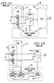
- a prior art network element 100 comprises port interfaces 1-x 101 for receiving signals from the network, a switch fabric 102, port interface 103 for passing signals from switch fabric 102, and a complex control element 104 for controlling all port and switch functions within the network element.
- Port interfaces 1-x 101 each typically includes a signal monitoring element 105 for monitoring the signal status of incoming signals.
- prior art systems having this architecture have numerous disadvantages relating to the coupled control within complex control element 104 as well as the inability to propagate signal status information for incoming signals.
- FIG. 1B shows an expanded view of complex control element 104 from FIG. 1A, which could be used in a typical protection switching scheme.
- Complex control element 104 includes fabric control 110 as well as non-fabric controls such as fault detection controls 1-x 111, wherein a fault detection control 111 is provided for each input signal 1 to x. In operation, a protection switching decision would not be made by fabric control 110 until signal status is resolved for each input signal via fault detection controls 1-x 111.
- Fault detection controls 1-x 111 are typically further coupled to the signal monitoring element 105 within port interfaces 1-x 101. Therefore, complex control element 104 is fully coupled with respect to port interfaces 1-x 101 and switch fabric 102 of network element 100.
- the present invention fills this need and others by incorporating an embedded signal status protocol in a control system for a centralized switch fabric.
- the embedded signal status protocol reduces the complexity of the control arrangement because multiple control functions do not have to be closely coupled to facilitate selection decisions.
- each input signal within a transmission path is monitored to derive signal status information, which is then individually encoded and embedded within the input signal.
- the embedded signal status is decoded and provided as input to control logic for processing at any point within the transmission path, as necessary.
- the control logic resolves an address for the single input signal that is to be selected from among all input signals based on the embedded signal status. In the case of a centralized switch fabric, the address resolved by the control logic would be used by the switch fabric to select the appropriate input signal corresponding to the resolved address.
- the control logic is configurable to support any given application, so that each configuration of control logic constitutes an application control set that supports the performance requirements of a particular application.
- FIG. 2 shows one illustrative embodiment of the present invention in the context of a network element used in digital transmission applications.
- network element 200 includes port interfaces 1-x 201 for receiving signals from the network, a centralized switch fabric 202 implemented as the switch function, a port interface 203 for passing signals from switch fabric 202, and at least one decoupled control element 204 for controlling switch fabric 202.
- Port interfaces 1-x 201 can include signal monitoring/encoding elements 205 for monitoring the incoming signals and encoding the status of the incoming signals.
- Port interfaces 1-x 201 pass the signals along with the encoded status to switch fabric 202.
- Port interfaces 201 and 203 are therefore used to provide interface functions between switch fabric 202 and the various input and output signals.
- control element 204 is decoupled from port interfaces 1-x 201 and 203 unlike the prior art arrangements.
- control element 204 is adapted to receive signal status information for each of the input signals and further adapted to provide a control input to switch fabric 202 to effect a selection decision.
- the down arrow into control element 204 represents the signal status information, e.g., the quality information for incoming signals
- the up arrow from control element 204 represents the control input for the selection decision.
- Switch fabric 202 is controlled locally in that only signal status information that is local to a particular selection function within fabric 202 is used to make the appropriate selection decision.
- This localized control is achieved in the present invention by using an embedded signal status, whereby signal status information is encoded along with the signal data for each of the inputs to switch fabric 202. Consequently, signal status information propagates through the network element along with the signal data and, as a result, a selection decision is made without having to trace back and resolve signal status for previously selected input signals.
- FIG. 3 shows an expanded view of the functional signal flow between control element 204 and switch fabric 202.
- FIG. 3 shows a single routing component 210 (e.g., selector 210) in switch fabric 202.
- a routing component 210 e.g., selector 210
- many types of routing structures having complex hardware and/or software implementations are contemplated for realizing switch fabric 202. Examples could include an array of hardware selectors, link lists, as well as other implementations known to those skilled in the art.
- SD status decoder
- status decoder 431 decodes the encoded status information and passes the decoded status information on to control element 204. It should be noted that the encoded status of each input signal also propagates along with the input signal to selector 210.
- Control element 204 uses appropriate control logic to generate a control input signal to selector 210.
- the control input signal shown by the up arrow from control element 204, includes the address of the particular input signal to be selected by selector 210 in switch fabric 202. In response to the control input signal, selector 210 switches out the appropriate output signal from fabric 202.
- control element 204 comprises control logic for resolving an address of a particular input signal based on the embedded signal status for each of the input signals.
- Control element 204 may include multiple stages of selectors and associated domain control elements selectively configured to resolve an address of a single input signal based on performance criteria for a particular application, such as "path-in-line” protection switching.
- U.S. patent application Serial No. 08/942096 entitled “A Control Architecture for a Homogeneous Routing Structure” (Bordogna 4-7-8-2-3), which is incorporated herein by reference, describes one approach for implementing control element 204.
- the embedded signal status information associated with each of the input signals is not removed during any of the control or switching operations, and as a result, signal status is preserved through the system.
- the embedded signal status protocol of the present invention eliminates the need to interface control element 204 with any type of fault detection control in the port interface. Thus, control of the switch fabric can be fully decoupled from other control functions.
- FIGS. 4A and 4B provide a more detailed illustration of the embedded signal status protocol of the present invention.
- FIG. 4A is a simplified flow diagram showing how the signal status is embedded within the input signal.
- an input signal is provided to both a signal monitoring element 410 and to a status encoding element 420 within signal monitoring/encoding element 205.
- signal monitoring element 410 Based on predetermined failure conditions or other performance criteria, signal monitoring element 410 outputs a signal status to status encoding element 420.
- Status encoding element 420 embeds the signal status information provided by signal monitoring element 410 and outputs the data from the input signal along with its embedded signal status information.
- signal monitoring element 410 and status encoding element 420 can be implemented using techniques well known in the art.
- FIG. 4B there is shown a more detailed illustration of the use of the embedded signal status protocol in the present invention. More specifically, FIG. 4B shows a signal interface portion 400 and a signal switch/selector portion 401. These blocks could be co-located in the same chassis or could be located in separate chassis. As compared with the embodiment shown in FIG. 2, signal interface portion 400 would include some of the functions of port interfaces 201 and signal switch/selector portion 401 would include some of the functions of switch fabric 202 and control element 204.
- Interface portion 400 is shown to receive m channels of n input signals, e.g., base-rate signals (BRS) 402, labeled as BRS 1,1 to BRS n,m where BRS n,m represents BRS n of channel m .
- BRS base-rate signals
- a base-rate signal is a signal of a fundamental rate or structure, which could also be combined with other similar base-rate signals to create a higher rate and/or more complex signal.
- each BRS 402 has an independent quality monitor 410, shown here as MON 1,1 to MON n,m , where MON n,m represents quality monitor for BRS n of channel m .
- Quality monitor 410 is responsible for measuring the quality and or state of its respective BRS 402.
- Quality monitor 410 reports the BRS quality to a respective signal status encode function, shown here as status encoder (SE) 420, for the associated BRS 402.
- SE status encoder
- many different quality and/or status levels are available for encoding in status encoder 420.
- the embedded signal status protocol of the present invention supports a wide range of status control because many different status codes, each possibly representing a different status condition (e.g., quality, time-related parameters, etc.), may be encoded along with the signal.
- Status encoder 420 inserts an encoded value into the respective BRS 402, with the encoded value representing the quality or state of the respective BRS 402. From this point forward (within the architectural bounds of the system), BRS 402 now contains both its original data along with its encoded status. As such, the signal status propagates through the system, thereby eliminating the need to "rediscover" the signal status at any subsequent stage in the system.
- the signal would typically have to be monitored again at any subsequent input port to "rediscover" its signal status before the next selection decision could be made.
- the present invention allows for monitoring at the interface boundary where the signal first enters the system as compared with prior art systems that require monitoring functions throughout the system and/or complex control structures to share information between control functions.
- switch/selector portion 401 is an m-channel base-rate signal selector switch that includes m selectors 430 corresponding to m BRS channels. Each selector 430 selects from n BRS 402 inputs.
- the signal status decode function implemented here as status decoder (SD) 431, is provided at each input to each selector 430 for locating the encoded status information carried within the respective BRS 402, for decoding the encoded status information if necessary, and for passing the decoded status information on to select logic 435.
- Select logic 435 evaluates the quality of all the inputs associated with selector 430 under its control and will command selector 430 to choose the most appropriate input. As compared with FIGS. 2 and 3, select logic 435 in FIG.
- status decoder 431 does not remove the encoded status information from BRS 402, so that the output of each selector 430 contains the selected BRS 402 that includes the original BRS data for that signal along with the encoded status that was inserted at interface portion 400.
- this architecture assures that all switching decisions can be made locally at each switch/selector portion 401. Importantly, this architecture eliminates the need to share signal status information across functional portions using a complex (overlay) control structure. Moreover, this architecture directly supports multiple levels or stages of switching that can be either centralized or distributed.
- the embedded signal status protocol can be used for a centralized switch fabric that uses either a common control arrangement or a segmented control arrangement.
- the embedded signal status protocol is well-suited for the segmented control arrangement described in U.S. patent application Serial No. 08/942096, entitled "A Control Architecture for a Homogeneous Routing Structure” (Bordogna 4-7-8-2-3), incorporated herein by reference.
- select logic 435 may be comprised of multi-stage, application specific address resolution functions 501.
- Each application specific address resolution function 501 includes control logic that can be selectively configured to resolve a single control input to switch fabric 202. More specifically, each application specific address resolution function 501 can include a number of logic stages selectively configured with an appropriate number and arrangement of selectors 510 and associated domain control functions 511.
- switch fabric 202 receives a number of inputs S i , represented as 1-W A inputs, and generates a number of outputs S o , represented as 1-Y A outputs.
- Application specific address resolution functions 501 are coupled to switch fabric 202 with the number of application specific address resolution functions 501 being equal to the number of outputs S o so that each of the 1-Y A control inputs to switch fabric 202 is independently mapped to one of the 1-Y A outputs S o .
- the address information and signal status information for each of the 1-W A inputs is provided as input to the application specific address resolution functions 501.
- Application specific address resolution functions 501 are adapted to receive the address and signal status information from the 1-W A inputs and are further adapted to perform selection functions to generate a single control input based on the signal status information.
- the single control input provided to switch fabric 202 would include the address of the input signal that is to be selected by switch fabric 202.
- each application specific address resolution function 501 is independent from each other, each application specific address resolution function 501 can be configured to provide "resolved" control of a single output S o .
- switch fabric 202 is "channelized” because of the one for one association between application specific address resolution functions 501 and 1-Y A outputs. As such, switch fabric 202 can simultaneously support 1-Y A separate applications in parallel on a centralized switch fabric 202, because each "channel" of the switch fabric supports a separate application.
- the present invention may be suitable for a sensor system used in automobiles or for an alarm/surveillance system that uses sensors placed at peripheral points along a data path that extends through a facility. Status from the sensors could be combined with the signal and propagated as necessary for appropriate use by a central processing point, such as a control center.
- the signal status can be combined with the signal data in many different ways, such as by using a telemetry channel, or by modulating the amplitude, frequency, or phase of the signal data, to name a few.
- the embedded signal status could be used for other than switching decisions.
- the present invention could be used for fault isolation, identification and/or segmentation applications in which an embedded signal status is used to manage faults in a multi-span, serial transmission path. In general, any application that could benefit from using an embedded control mechanism would be a candidate for the present invention.
Landscapes
- Engineering & Computer Science (AREA)
- Computer Networks & Wireless Communication (AREA)
- Signal Processing (AREA)
- Computer Security & Cryptography (AREA)
- Data Exchanges In Wide-Area Networks (AREA)
- Maintenance And Management Of Digital Transmission (AREA)
- Time-Division Multiplex Systems (AREA)
- Emergency Protection Circuit Devices (AREA)
Applications Claiming Priority (2)
| Application Number | Priority Date | Filing Date | Title |
|---|---|---|---|
| US08/942,095 US6081503A (en) | 1997-10-01 | 1997-10-01 | Control architecture using an embedded signal status protocol |
| US942095 | 1997-10-01 |
Publications (3)
| Publication Number | Publication Date |
|---|---|
| EP0907302A2 true EP0907302A2 (de) | 1999-04-07 |
| EP0907302A3 EP0907302A3 (de) | 2001-01-17 |
| EP0907302B1 EP0907302B1 (de) | 2006-11-08 |
Family
ID=25477568
Family Applications (1)
| Application Number | Title | Priority Date | Filing Date |
|---|---|---|---|
| EP98307693A Expired - Lifetime EP0907302B1 (de) | 1997-10-01 | 1998-09-22 | Steuerungsarchitektur mittels eingebetteten Signalinformationen |
Country Status (8)
| Country | Link |
|---|---|
| US (1) | US6081503A (de) |
| EP (1) | EP0907302B1 (de) |
| JP (1) | JP3357295B2 (de) |
| KR (1) | KR19990036711A (de) |
| CN (1) | CN1213917A (de) |
| CA (1) | CA2247951C (de) |
| DE (1) | DE69836365T2 (de) |
| IL (1) | IL126400A0 (de) |
Cited By (1)
| Publication number | Priority date | Publication date | Assignee | Title |
|---|---|---|---|---|
| WO2002009349A2 (en) * | 2000-07-20 | 2002-01-31 | Nortel Networks Limited | Apparatus and method for optical communication protection |
Families Citing this family (11)
| Publication number | Priority date | Publication date | Assignee | Title |
|---|---|---|---|---|
| US6693904B1 (en) * | 1998-04-09 | 2004-02-17 | Lucent Technologies Inc. | Trace format for a sliced switch fabric |
| US6560202B1 (en) * | 1998-07-27 | 2003-05-06 | Lucent Technologies Inc. | Control architecture using a multi-layer embedded signal status protocol |
| US6628648B1 (en) * | 1998-09-18 | 2003-09-30 | The United States Of America As Represented By The Secretary Of The Navy | Multi-interface point-to-point switching system (MIPPSS) with hot swappable boards |
| US6925052B1 (en) * | 1999-10-01 | 2005-08-02 | Agilent Technologies, Inc. | Multi-channel network monitoring apparatus, signal replicating device, and systems including such apparatus and devices, and enclosure for multi-processor equipment |
| TWI245507B (en) * | 2002-08-06 | 2005-12-11 | Realtek Semiconductor Corp | System and method for network connection detection |
| KR100454506B1 (ko) * | 2002-11-14 | 2004-10-28 | 한국전자통신연구원 | 중앙집중형 관리방식의 대용량 스위치 패브릭 및 그 관리방법 |
| US7508752B1 (en) | 2003-05-30 | 2009-03-24 | Cisco Technology, Inc. | Hardware facility switching in cross-connect systems |
| US20060080157A1 (en) * | 2004-10-12 | 2006-04-13 | Shuker Thomas J | Method of improving administrative functions of a business using value streams with display of status |
| US7512060B1 (en) * | 2004-12-17 | 2009-03-31 | Michael Ho | Method and apparatus for providing a connection matrix |
| US9337959B2 (en) * | 2013-10-14 | 2016-05-10 | Applied Micro Circuits Corporation | Defect propagation of multiple signals of various rates when mapped into a combined signal |
| EP3139548B1 (de) * | 2015-09-04 | 2018-04-11 | Airbus Operations | Hochzuverlässiges getrenntes gateway zur verbindung von verschiedenen domänen |
Citations (3)
| Publication number | Priority date | Publication date | Assignee | Title |
|---|---|---|---|---|
| EP0579040A2 (de) * | 1992-07-17 | 1994-01-19 | Alcatel N.V. | Verbindungssicherung in einem digitalen Fernmeldesystem |
| JPH0897841A (ja) * | 1994-09-29 | 1996-04-12 | Hitachi Ltd | パス切替伝送装置の制御方法及びパス切替伝送装置 |
| EP0840472A2 (de) * | 1996-10-29 | 1998-05-06 | Nortel Networks Corporation | Pfadschutz in einem Telekommunikationsnetzwerk |
Family Cites Families (5)
| Publication number | Priority date | Publication date | Assignee | Title |
|---|---|---|---|---|
| US4847877A (en) * | 1986-11-28 | 1989-07-11 | International Business Machines Corporation | Method and apparatus for detecting a predetermined bit pattern within a serial bit stream |
| US5008882A (en) * | 1987-08-17 | 1991-04-16 | California Institute Of Technology | Method and apparatus for eliminating unsuccessful tries in a search tree |
| US5465256A (en) * | 1993-12-23 | 1995-11-07 | Krone Ag | Telephone cross connect status signal pre-processor |
| US5636203A (en) * | 1995-06-07 | 1997-06-03 | Mci Corporation | Method and system for identifying fault locations in a communications network |
| US5838684A (en) * | 1996-02-22 | 1998-11-17 | Fujitsu, Ltd. | Low latency, high clock frequency plesioasynchronous packet-based crossbar switching chip system and method |
-
1997
- 1997-10-01 US US08/942,095 patent/US6081503A/en not_active Expired - Lifetime
-
1998
- 1998-09-22 EP EP98307693A patent/EP0907302B1/de not_active Expired - Lifetime
- 1998-09-22 DE DE69836365T patent/DE69836365T2/de not_active Expired - Lifetime
- 1998-09-23 CA CA002247951A patent/CA2247951C/en not_active Expired - Lifetime
- 1998-09-28 IL IL12640098A patent/IL126400A0/xx unknown
- 1998-09-30 CN CN98119404A patent/CN1213917A/zh active Pending
- 1998-09-30 JP JP27735198A patent/JP3357295B2/ja not_active Expired - Lifetime
- 1998-09-30 KR KR1019980040769A patent/KR19990036711A/ko not_active Application Discontinuation
Patent Citations (3)
| Publication number | Priority date | Publication date | Assignee | Title |
|---|---|---|---|---|
| EP0579040A2 (de) * | 1992-07-17 | 1994-01-19 | Alcatel N.V. | Verbindungssicherung in einem digitalen Fernmeldesystem |
| JPH0897841A (ja) * | 1994-09-29 | 1996-04-12 | Hitachi Ltd | パス切替伝送装置の制御方法及びパス切替伝送装置 |
| EP0840472A2 (de) * | 1996-10-29 | 1998-05-06 | Nortel Networks Corporation | Pfadschutz in einem Telekommunikationsnetzwerk |
Non-Patent Citations (3)
| Title |
|---|
| "CHARACTERISTICS OF SYNCHRONOUS DIGITAL HIERARCHY (SDH) EQUIPMENT FUNCTIONAL BLOCKS" ITU-T RECOMMENDATION G.783 (01/94), XP002152719 * |
| ANDERSON J ET AL: "VIRTUAL PATH GROUP PROTECTION SWITCHING - A METHOD FOR FAST ATM NETWORK SURVIVABILITY" BELL LABS TECHNICAL JOURNAL, SPRING 1997, vol. 2, no. 2, pages 213-232, XP000695177 ISSN: 1089-7089 * |
| PATENT ABSTRACTS OF JAPAN vol. 1996, no. 08, 30 August 1996 (1996-08-30) & JP 08 097841 A (HITACHI LTD), 12 April 1996 (1996-04-12) * |
Cited By (4)
| Publication number | Priority date | Publication date | Assignee | Title |
|---|---|---|---|---|
| WO2002009349A2 (en) * | 2000-07-20 | 2002-01-31 | Nortel Networks Limited | Apparatus and method for optical communication protection |
| WO2002009349A3 (en) * | 2000-07-20 | 2002-09-19 | Nortel Networks Ltd | Apparatus and method for optical communication protection |
| US6934248B1 (en) | 2000-07-20 | 2005-08-23 | Nortel Networks Limited | Apparatus and method for optical communication protection |
| US7593322B2 (en) | 2000-07-20 | 2009-09-22 | Nortel Networks Limited | Apparatus and method for optical communication protection |
Also Published As
| Publication number | Publication date |
|---|---|
| JPH11177553A (ja) | 1999-07-02 |
| DE69836365T2 (de) | 2007-10-11 |
| EP0907302B1 (de) | 2006-11-08 |
| KR19990036711A (ko) | 1999-05-25 |
| IL126400A0 (en) | 1999-05-09 |
| JP3357295B2 (ja) | 2002-12-16 |
| CA2247951A1 (en) | 1999-04-01 |
| CA2247951C (en) | 2001-09-04 |
| US6081503A (en) | 2000-06-27 |
| EP0907302A3 (de) | 2001-01-17 |
| CN1213917A (zh) | 1999-04-14 |
| DE69836365D1 (de) | 2006-12-21 |
Similar Documents
| Publication | Publication Date | Title |
|---|---|---|
| US6560202B1 (en) | Control architecture using a multi-layer embedded signal status protocol | |
| JP3581765B2 (ja) | 複合リング形ネットワークシステムにおけるパス切替方法及び装置 | |
| US6249510B1 (en) | Signal protection system for bi-direction ring network | |
| US6081503A (en) | Control architecture using an embedded signal status protocol | |
| US6795393B1 (en) | Method and apparatus for errorless path protection and rearrangement | |
| US20090092044A1 (en) | Selector in switching matrix, line redundant method, and line redundant system | |
| JP2001024522A (ja) | エラー訂正符号装置、エラー訂正符号復号装置および伝送装置 | |
| US5790520A (en) | Path protection switch ring system for line saving even though line setting operation was not carried out | |
| US7187649B1 (en) | Method and apparatus for providing network protection at input/output interfaces of a cross-connect switch | |
| CA2299974C (en) | Wdm network and wdm network device | |
| US6301228B1 (en) | Method and apparatus for switching signals using an embedded group signal status | |
| US6393019B1 (en) | Matrix switch | |
| US6137790A (en) | Control architecture for a homogeneous routing structure | |
| JP2000196524A (ja) | 故障が存在する状態で伝送用光ファイバ大洋横断ms―spリング内の低優先順位チャネルの可用度を最適化する方法および装置 | |
| US7602701B1 (en) | WideBand cross-connect system and protection method utilizing SONET add/drop multiplexers | |
| US20040141532A1 (en) | Multiplexer and usage thereof | |
| JPH11252049A (ja) | 波長多重通信網における不要警報抑止方法および装置 | |
| JP3334868B2 (ja) | 同期光伝送装置 | |
| CA2287607A1 (en) | Distributed 1xn protection switching architecture | |
| WO2000031927A1 (en) | Method for establishing alternative routes in a telecommunication network | |
| EP1429483A1 (de) | Defektsignalisierung für Hardware unterstützte Ersatzschaltung in einem optischen Querverbindungssystem | |
| Whitt et al. | Service protection for synchronous networks | |
| WO2002011335A2 (en) | Multi-layer control interface for a cross-connect switch matrix | |
| EP1133853A1 (de) | Verfahren zur errichtung von alternativen leitwegen in einem kommunikationsnetz |
Legal Events
| Date | Code | Title | Description |
|---|---|---|---|
| PUAI | Public reference made under article 153(3) epc to a published international application that has entered the european phase |
Free format text: ORIGINAL CODE: 0009012 |
|
| AK | Designated contracting states |
Kind code of ref document: A2 Designated state(s): DE FR |
|
| AX | Request for extension of the european patent |
Free format text: AL;LT;LV;MK;RO;SI |
|
| PUAL | Search report despatched |
Free format text: ORIGINAL CODE: 0009013 |
|
| AK | Designated contracting states |
Kind code of ref document: A3 Designated state(s): AT BE CH CY DE DK ES FI FR GB GR IE IT LI LU MC NL PT SE |
|
| AX | Request for extension of the european patent |
Free format text: AL;LT;LV;MK;RO;SI |
|
| 17P | Request for examination filed |
Effective date: 20010704 |
|
| AKX | Designation fees paid |
Free format text: DE FR |
|
| GRAP | Despatch of communication of intention to grant a patent |
Free format text: ORIGINAL CODE: EPIDOSNIGR1 |
|
| GRAS | Grant fee paid |
Free format text: ORIGINAL CODE: EPIDOSNIGR3 |
|
| GRAA | (expected) grant |
Free format text: ORIGINAL CODE: 0009210 |
|
| AK | Designated contracting states |
Kind code of ref document: B1 Designated state(s): DE FR |
|
| REF | Corresponds to: |
Ref document number: 69836365 Country of ref document: DE Date of ref document: 20061221 Kind code of ref document: P |
|
| ET | Fr: translation filed | ||
| PLBE | No opposition filed within time limit |
Free format text: ORIGINAL CODE: 0009261 |
|
| STAA | Information on the status of an ep patent application or granted ep patent |
Free format text: STATUS: NO OPPOSITION FILED WITHIN TIME LIMIT |
|
| 26N | No opposition filed |
Effective date: 20070809 |
|
| REG | Reference to a national code |
Ref country code: FR Ref legal event code: CD Owner name: ALCATEL-LUCENT USA INC. Effective date: 20131122 |
|
| REG | Reference to a national code |
Ref country code: FR Ref legal event code: GC Effective date: 20140410 |
|
| REG | Reference to a national code |
Ref country code: FR Ref legal event code: RG Effective date: 20141015 |
|
| REG | Reference to a national code |
Ref country code: FR Ref legal event code: PLFP Year of fee payment: 18 |
|
| REG | Reference to a national code |
Ref country code: FR Ref legal event code: PLFP Year of fee payment: 19 |
|
| REG | Reference to a national code |
Ref country code: FR Ref legal event code: PLFP Year of fee payment: 20 |
|
| PGFP | Annual fee paid to national office [announced via postgrant information from national office to epo] |
Ref country code: DE Payment date: 20170928 Year of fee payment: 20 Ref country code: FR Payment date: 20170928 Year of fee payment: 20 |
|
| REG | Reference to a national code |
Ref country code: DE Ref legal event code: R071 Ref document number: 69836365 Country of ref document: DE |