EP0906862A2 - Lenkungsmechanismus für Kraftfahrzeug - Google Patents
Lenkungsmechanismus für Kraftfahrzeug Download PDFInfo
- Publication number
- EP0906862A2 EP0906862A2 EP98118280A EP98118280A EP0906862A2 EP 0906862 A2 EP0906862 A2 EP 0906862A2 EP 98118280 A EP98118280 A EP 98118280A EP 98118280 A EP98118280 A EP 98118280A EP 0906862 A2 EP0906862 A2 EP 0906862A2
- Authority
- EP
- European Patent Office
- Prior art keywords
- pinion
- rack
- tubular housing
- bearing
- shaft
- Prior art date
- Legal status (The legal status is an assumption and is not a legal conclusion. Google has not performed a legal analysis and makes no representation as to the accuracy of the status listed.)
- Granted
Links
Images
Classifications
-
- B—PERFORMING OPERATIONS; TRANSPORTING
- B62—LAND VEHICLES FOR TRAVELLING OTHERWISE THAN ON RAILS
- B62D—MOTOR VEHICLES; TRAILERS
- B62D5/00—Power-assisted or power-driven steering
- B62D5/06—Power-assisted or power-driven steering fluid, i.e. using a pressurised fluid for most or all the force required for steering a vehicle
- B62D5/20—Power-assisted or power-driven steering fluid, i.e. using a pressurised fluid for most or all the force required for steering a vehicle specially adapted for particular type of steering gear or particular application
- B62D5/22—Power-assisted or power-driven steering fluid, i.e. using a pressurised fluid for most or all the force required for steering a vehicle specially adapted for particular type of steering gear or particular application for rack-and-pinion type
-
- B—PERFORMING OPERATIONS; TRANSPORTING
- B62—LAND VEHICLES FOR TRAVELLING OTHERWISE THAN ON RAILS
- B62D—MOTOR VEHICLES; TRAILERS
- B62D3/00—Steering gears
- B62D3/02—Steering gears mechanical
- B62D3/12—Steering gears mechanical of rack-and-pinion type
Definitions
- the invention relates to improvements in steering mechanism assemblies for automotive vehicles, particularly with the aim of solving problems of the mechanical design and alignment of housing elements for accommodating the various components of the steering mechanism, particularly the steering control linkage, and with the aim of improving the conditions, functioning, and engagement of the steering mechanism components, particularly those of the steering control linkage.
- a further object of the invention is to improve the steering control linkage such that correct frictional contact is maintained between the interengaged dentations (those of the rack and pinion), within the established limits of tolerance, in response to axial stresses present in the articulations of the housing which tend to urge the rack into a position distant from and out of proper engagement with the pinion and back into tighter engagement, which stresses thereby result in generation of undesirable noise.
- the principal end product of the invention is a steering control linkage housing of simple structure for control linkages for unassisted (manual) mechanical steering or power steering, which control linkages employ a rack and pinion, wherewith the subject housing incorporates means to improve the conditions of engagement of the rack and pinion in the face of axial stresses present in the housing, which stresses cause undesirable noise during the operation of the vehicle.
- Conventional steering control linkage housings are fabricated by casting of molten aluminum or other materials.
- a valve housing comprised generally of cast iron is also used in the case of power steering.
- the fabrication of such components is attended by various problems. Complex and precise procedures are required for assembly and alignment of a cast iron valve housing with a cast aluminum steering control linkage housing, to ensure correct skew angular positioning of the components of the steering control linkage.
- the alignment procedures may require different skew angular alignments depending on the particular variant of the steering system used, and necessitate the use of different casting molds for fabricating the elements of the steering control linkage housings and for adapting the power-assisted steering valve housing. For each situation, a specific skew angular alignment of the steering column shaft (pinion shaft) and the rack housing is required, in order for the steering system to function properly.
- This noise problem may be due to incorrect alignment of the contoured openings in the housing, but the main cause of steering system noise is axial stresses in the joints between the housing and the chassis, which stresses give rise to a force component perpendicular to the rack bar and tending to distance the rack bar from the pinion, thereby acting counter to the means integrated in the steering assembly which are intended to regulate the relative positions of the rack and pinion.
- the said axial stresses also act axially on the rack, which rack is generally mounted with releasable support means on an end bearing in the steering control linkage housing, wherewith in addition to the component of said stresses which act perpendicularly to the rack, the axial stresses give rise to an undesirable axial movement of the rack which interferes with correct interengagement of the rack and the pinion, again tending to cause the respective dentations to separate, wherewith when, in alleviation of this separation, the rack tends to return to its initial position.
- the result is noise, in an intensity and frequency which depend exclusively on the intensity of the abovementioned axial stresses.
- the conventional means used by automobile manufacturers to address these drawbacks in steering control linkages is to use high precision molds for fabricating the housings, in order to achieve the correct alignment of the steering control linkage components.
- the concept is that substantial improvement in operation will result from improvements in such alignment.
- the known technique of providing devices which periodically regulate the position of the rack bar has been used.
- the general such device comprises a manually adjustable thrust bearing which is elastically urged counter to the direction of the axial stresses. These devices function well, but when over-adjusted (which is always a possibility) the result is that the rack bar is not properly re-engaged, which is detrimental to the mechanism because the re-engagement force is too great or too small, either momentarily (dynamically) or on a sustained basis.
- a housing for steering control linkages which housing has a particular structure which enables correct mutual alignment --which may be selected from a range of possible mutual alignments -- of housing elements for the rack bar and the pinion (which pinion is fixed to the steering column shaft), wherewith if power-assisted steering is to be employed the housing elements may further comprise a structure for adapting to a power steering valve housing.
- the inventive housing is comprised of a pair of tubular housing elements formed from steel tubes, which elements are readily machinable over their entire length. These two tubular elements are joined together in a precise skew angular arrangement as required by the particular steering control linkage.
- the steel tubular elements are joined with the aid of contoured openings cut into the tube walls which openings have suitably coordinating shapes, such that when the tubular elements are superposed in the precise prescribed skew angular orientation, they can be joined together by welding or brazing at the superposed borders of the contoured openings.
- the described structure of the steering control linkage housing is simple in design. It eliminates the problems of porosity which cast housings present, facilitates the mechanical alignment of the parts of the housing in coordination with the rack bar and pinion which the housing accommodates, eliminates the need for tooling in the nature of molds which would need to be re-tooled for each variation in the skew angular alignment of the housing elements, facilitates the provision of support means for support bearings for the rack bar (e.g. because the inventive housing is readily machinable), and facilitates the exact positioning of elements of the housing which are differently positioned in different versions of conventional housings.
- the alignment and positioning features of the inventive housing result in improved functioning of the steering mechanism.
- the inventive housing may be combined with means of automatically and accurately positioning the pinion in proper engagement with the rack, in response to displacement of the rack due to components of the abovementioned axial stresses.
- These automatic positioning means may be disposed in the housing element in which the pinion is housed, and may comprise an elastic organ (e.g. spring, elastic annular piece, or elastic cylindrical piece) which urges the pinion component of the steering control linkage (which pinion may be conical or cylindrical) into proper engagement with the rack when the rack becomes separated from the pinion due to stress components generated by the abovementioned axial stresses.
- an elastic organ e.g. spring, elastic annular piece, or elastic cylindrical piece
- said means are mounted in the immediate neighborhood of, and in cooperation with, a conical pinion disposed at the end of the steering column shaft.
- the dentation of said pinion corresponds to that of the rack, and does not per se provide any type of exaggerated pre-stressing against the rack.
- the rack receives additional support within the proposed housing element by mounting therein of a second guide bearing (pillow bearing) which keeps the rack aligned in said housing element in order to counter the generation of undesirable movement by the action of the abovementioned axial stresses.
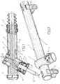
- the housing 1 is an inventive steering control linkage housing similar to known steering control linkage housings in that it is intended as a housing to accommodate various steering control linkage components including a rack 2 and a pinion 3.
- the pinion 3 is mounted on the steering column shaft c .
- the rack is supported by way of a pillow bearing (bushing bearing) 2' disposed at the distal end of the rack.
- the housing 1 is comprised of two tubular elements (1', 1'') shown in more detail in Figs. 2 and 3.
- elements (1', 1'') both comprise steel tubes; but alternatively the element 1' which serves as a housing element for the rack 2 may comprise a steel tube, and the element 1'' which serves as a housing element for the pinion 3 may comprise a cast iron tube.
- the tubular elements 1' and 1'' of which the housing 1 is comprised are each easily machinable over their entire lengths. This feature allows precision machining to produce shoulders, seats, and like structures in their interiors, to facilitate the mounting of the rack 2 and pinion 3, and to facilitate the application of clamps, brackets, and other mounting hardware (4) for mounting the steering control linkage housing to the vehicle chassis.
- the two tubes (1', 1'') are joined together with the aid of contoured openings (5, 5') cut into the respective tube walls (1', 1'').
- the perimeters of these openings are complementary such that appropriate support is provided when the tubes (1', 1'') are assembled together in a superposed crossed configuration the parameters of which are determined by the prescribed skew angular alignment of the steering control linkage components which results in the desired engagement of the rack 2 and pinion 3.
- the contoured opening 5' in element 1'' is smaller than the contoured opening 5 in element 1', whereby when the tubes are arranged in the desired superposed position the border region around the opening 5' provides a support for the element 1'' (Fig. 4) which facilitates the establishment of the relative angular position of the elements (1', 1'') and subsequent welding or brasing.
- This manner of joining the two elements (1', 1'') allows variations in the angular relations depending on the needs of various steering mechanisms, and avoids the difficulties in alignment when pre-cast elements are used.
- steering control linkage housings according to the invention can be produced for a somewhat wide range of vehicles, from the same stock pieces and with the same tooling (instead of a whole series of different casting molds).
- tubular element 1'' is comprised of cast iron, one may readily incorporate in it a structure 6 for mounting a valve complex, which structure 6 will have the proper configuration for good operation.
- a housing 1 thus constructed enables proper alignment of the rack bar 2 and the pinion 3, along with means of automatically positioning said rack bar 2 and pinion 3 in response to axial stresses exerted on said housing 1.
- a first embodiment of the described positioning means is illustrated in Figs. 1 and 3.
- the dentation of the conical pinion 3 corresponds to that of the rack 2.
- the pinion 3 is accommodated in the tubular element 1'' of the housing 1.
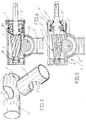
- the pinion shaft 7 is coaxially connected to the steering column (c) and is rotationally supported and is movable to a slight degree in the axial direction, on one side by the intermediary of a bearing 8 which closes off the end of the tubular element 1'', and on the other side by an antifriction bearing 9 mounted in the opposite end region of tubular element 1'', which end region is closed off by retainer means and a conventional end cap, collectively designated with reference numeral 10.
- the support means for the conical pinion 3 incorporates an elastic organ 11 in the form of a plate spring or elastic annular piece, which organ 11 exerts a continuous pre-stress on the conical pinion 3 in the axial direction.
- elastic organ 11 is mounted between:
- the frictional engagement characteristics of the dentations is determined by the pre-stressing of the pinion 3 by the elastic organ 11, as a consequence of the conicity of the pinion 3.
- excess engagement force between the rack 2 and pinion 3 is avoided, in that the resultant force component derived from the axial stresses, in the rack 2, is compensated.
- a final element of an assembly which annuls possible stresses on the rack 2 is provided by a second pillow bearing 13 which supports the rack in the neighborhood of the junction of the two tubular elements (1', 1''); this along with the conicity of the pinion 3 contributes to the proper functioning of the steering mechanism.
- Fig. 5 shows a variant of the embodiment of the inventive automatic pinion-positioning means shown in Fig. 4, wherein a generally annular spring 11' acts directly on an end-disposed antifriction bearing 9' which is mounted on the shaft 7 of the conical pinion 3.
- a retaining ring 12' mounted in a threaded plug piece 14 threadedly engaged in the interior of the tubular element 1'', which plug piece 14 also surrounds the elastic organ 11'.
- the described arrangements enable undesirable movements of the rack 2 to be resisted, thereby eliminating undesirable noise in the steering mechanism.
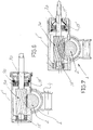
- the means of automatically positioning the components of the steering control linkage assembly incorporated in the described housing 1 are comprised of quasi-cylindrical pieces of elastic material (15, 15') having eccentric openings, for supporting the shaft 7a of a cylindrical pinion 3a which engages a rack 2.
- the elastic piece 15 is disposed at the end region of shaft 7a which end region corresponds to the blind end of the tubular element 1'; the elastic piece 15' is disposed around the antifriction bearing 9a, wherewith the end of tubular element 1'' which is opposite from the end which bears the first elastic piece 15 is closed off by a retaining ring and a conventional plug piece as in the preceding embodiment.
- the described embodiments allow one to dispense with the conventional devices for regulating the engagement of the components of the steering control linkage, and to dispense with all of the appurtenances to said regulating devices. Not only are costs reduced, but more importantly the undesirable noises are eliminated.
Landscapes
- Engineering & Computer Science (AREA)
- Chemical & Material Sciences (AREA)
- Combustion & Propulsion (AREA)
- Transportation (AREA)
- Mechanical Engineering (AREA)
- Transmission Devices (AREA)
Applications Claiming Priority (4)
| Application Number | Priority Date | Filing Date | Title |
|---|---|---|---|
| AR10456697 | 1997-10-03 | ||
| AR9704566 | 1997-10-03 | ||
| US09/095,943 US6283244B1 (en) | 1997-10-03 | 1998-06-12 | Steering mechanism assembly for automotive vehicle |
| US95943 | 1998-06-12 |
Publications (3)
| Publication Number | Publication Date |
|---|---|
| EP0906862A2 true EP0906862A2 (de) | 1999-04-07 |
| EP0906862A3 EP0906862A3 (de) | 2000-08-30 |
| EP0906862B1 EP0906862B1 (de) | 2003-12-10 |
Family
ID=25590815
Family Applications (1)
| Application Number | Title | Priority Date | Filing Date |
|---|---|---|---|
| EP19980118280 Expired - Lifetime EP0906862B1 (de) | 1997-10-03 | 1998-09-26 | Lenkungsmechanismus für Kraftfahrzeug |
Country Status (2)
| Country | Link |
|---|---|
| EP (1) | EP0906862B1 (de) |
| DE (1) | DE69820371T2 (de) |
Cited By (6)
| Publication number | Priority date | Publication date | Assignee | Title |
|---|---|---|---|---|
| EP1086881A1 (de) * | 1999-09-24 | 2001-03-28 | Renault | Zahnstangenlenk- Getriebegehäuse |
| FR2805236A1 (fr) * | 2000-02-22 | 2001-08-24 | Soc Mecanique Irigny | Dispositif de guidage de cremaillere pour mecanisme de direction de vehicule automobile |
| EP1129925A1 (de) * | 2000-02-29 | 2001-09-05 | Visteon Automotive Systems Inc. | Verbesserungen an Lenksystemen von Kraftfahrzeugen |
| GB2378163A (en) * | 2001-07-06 | 2003-02-05 | Visteon Global Tech Inc | Rack-and -pinion steering mechanism for an automotive vehicle |
| KR20160094022A (ko) * | 2015-01-30 | 2016-08-09 | 주식회사 만도 | 자동차의 랙 피니언 방식 조향장치 |
| CN108313122A (zh) * | 2017-01-16 | 2018-07-24 | 浙江师范大学 | 一种用于循环球液压转向器支撑调整塞摇臂轴式输出结构 |
Families Citing this family (2)
| Publication number | Priority date | Publication date | Assignee | Title |
|---|---|---|---|---|
| DE102014008961B4 (de) * | 2014-06-23 | 2016-12-15 | Thyssenkrupp Presta Ag | Lenkgetriebe mit deachsierter Zahnstange |
| DE102020208275A1 (de) | 2020-07-02 | 2022-01-05 | Robert Bosch Gesellschaft mit beschränkter Haftung | Modulare elektrische Hilfskraftlenkung |
Family Cites Families (6)
| Publication number | Priority date | Publication date | Assignee | Title |
|---|---|---|---|---|
| DE1073879B (de) * | 1957-04-03 | 1960-01-21 | Auto Union G.m.b.H., Ingolstadt/ Donau | Zahnstangenlenkvorrichtung, insbesondere für Kraftfahrzeuge |
| GB1248016A (en) * | 1969-09-25 | 1971-09-29 | Burman & Sons Ltd | Steering gear |
| US3788159A (en) * | 1972-10-30 | 1974-01-29 | Gen Motors Corp | Rack and pinion steering gear |
| US4016774A (en) * | 1975-12-19 | 1977-04-12 | The Bendix Corporation | Rack and pinion steering gear |
| DE2962985D1 (en) * | 1978-05-08 | 1982-07-22 | Cam Gears Ltd | Rack and pinion gears, housings therefor and a method of manufacturing such housings |
| DE4334491A1 (de) * | 1993-10-09 | 1995-04-13 | Zahnradfabrik Friedrichshafen | Zahnstangenlenkung, insbesondere für Kraftfahrzeuge |
-
1998
- 1998-09-26 DE DE69820371T patent/DE69820371T2/de not_active Expired - Fee Related
- 1998-09-26 EP EP19980118280 patent/EP0906862B1/de not_active Expired - Lifetime
Non-Patent Citations (1)
| Title |
|---|
| None |
Cited By (11)
| Publication number | Priority date | Publication date | Assignee | Title |
|---|---|---|---|---|
| EP1086881A1 (de) * | 1999-09-24 | 2001-03-28 | Renault | Zahnstangenlenk- Getriebegehäuse |
| FR2798896A1 (fr) * | 1999-09-24 | 2001-03-30 | Renault | Carter pour mecanisme de direction a pignon et cremaillere |
| FR2805236A1 (fr) * | 2000-02-22 | 2001-08-24 | Soc Mecanique Irigny | Dispositif de guidage de cremaillere pour mecanisme de direction de vehicule automobile |
| EP1127773A3 (de) * | 2000-02-22 | 2002-11-13 | Société de Mécanique d'Irigny | Zahnstangenführung für eine Kraftfahrzeuglenkung |
| EP1129925A1 (de) * | 2000-02-29 | 2001-09-05 | Visteon Automotive Systems Inc. | Verbesserungen an Lenksystemen von Kraftfahrzeugen |
| GB2378163A (en) * | 2001-07-06 | 2003-02-05 | Visteon Global Tech Inc | Rack-and -pinion steering mechanism for an automotive vehicle |
| GB2378163B (en) * | 2001-07-06 | 2003-07-16 | Visteon Global Tech Inc | Steering mechanism for an automotive vehicle |
| US6722465B2 (en) | 2001-07-06 | 2004-04-20 | Visteon Global Technologies, Inc | Steering mechanism for an automotive vehicle |
| KR20160094022A (ko) * | 2015-01-30 | 2016-08-09 | 주식회사 만도 | 자동차의 랙 피니언 방식 조향장치 |
| CN108313122A (zh) * | 2017-01-16 | 2018-07-24 | 浙江师范大学 | 一种用于循环球液压转向器支撑调整塞摇臂轴式输出结构 |
| CN108313122B (zh) * | 2017-01-16 | 2023-05-09 | 浙江师范大学 | 一种用于循环球液压转向器支撑调整塞摇臂轴式输出结构 |
Also Published As
| Publication number | Publication date |
|---|---|
| EP0906862B1 (de) | 2003-12-10 |
| DE69820371D1 (de) | 2004-01-22 |
| EP0906862A3 (de) | 2000-08-30 |
| DE69820371T2 (de) | 2004-11-11 |
Similar Documents
| Publication | Publication Date | Title |
|---|---|---|
| US6705176B2 (en) | Electric power steering apparatus | |
| EP1693279B1 (de) | Motorgetriebene Lenksäulenverstellvorrichtung | |
| US20140174843A1 (en) | Power steering device and backlash adjuster | |
| US5642918A (en) | Moveable headrest | |
| US20090031844A1 (en) | Tilt-type steering apparatus | |
| EP1065132A1 (de) | Elektrische Servolenkung | |
| JP2004507998A (ja) | 駆動装置 | |
| US6283244B1 (en) | Steering mechanism assembly for automotive vehicle | |
| EP0906862A2 (de) | Lenkungsmechanismus für Kraftfahrzeug | |
| US20030154815A1 (en) | Support casing for housing a steering shaft | |
| US5104190A (en) | Bushing for reducing lateral looseness in a pivot system | |
| CN113442996A (zh) | 转向装置 | |
| US4827788A (en) | Rack and pinion steering gear | |
| US4907776A (en) | Seat adjusting device | |
| US5393028A (en) | Power-operated seat device for vehicle | |
| JP2002302046A (ja) | ステアリング装置 | |
| US6193008B1 (en) | Rack-and-pinion assisted steering system | |
| US8336412B1 (en) | Electric power steering apparatus | |
| CN112013091B (zh) | 用于车辆动力转向组件的球式螺母组件的支承件 | |
| JP4085802B2 (ja) | 電動式パワーステアリング装置 | |
| KR950001211B1 (ko) | 시이트 조정장치 | |
| JP3624301B2 (ja) | ラックピニオン式舵取装置 | |
| US6692025B2 (en) | Tilt steering apparatus | |
| JP3548270B2 (ja) | 後輪用緩衝器のバネ荷重調整装置 | |
| JP3533281B2 (ja) | ラックピニオン式ステアリング装置 |
Legal Events
| Date | Code | Title | Description |
|---|---|---|---|
| PUAI | Public reference made under article 153(3) epc to a published international application that has entered the european phase |
Free format text: ORIGINAL CODE: 0009012 |
|
| AK | Designated contracting states |
Kind code of ref document: A2 Designated state(s): DE FR GB |
|
| AX | Request for extension of the european patent |
Free format text: AL;LT;LV;MK;RO;SI |
|
| RAP1 | Party data changed (applicant data changed or rights of an application transferred) |
Owner name: VISTEON AUTOMOTIVE SYSTEMS INC. |
|
| PUAL | Search report despatched |
Free format text: ORIGINAL CODE: 0009013 |
|
| AK | Designated contracting states |
Kind code of ref document: A3 Designated state(s): AT BE CH CY DE DK ES FI FR GB GR IE IT LI LU MC NL PT SE |
|
| AX | Request for extension of the european patent |
Free format text: AL;LT;LV;MK;RO;SI |
|
| 17P | Request for examination filed |
Effective date: 20010205 |
|
| AKX | Designation fees paid |
Free format text: DE FR GB |
|
| 17Q | First examination report despatched |
Effective date: 20020826 |
|
| GRAH | Despatch of communication of intention to grant a patent |
Free format text: ORIGINAL CODE: EPIDOS IGRA |
|
| GRAS | Grant fee paid |
Free format text: ORIGINAL CODE: EPIDOSNIGR3 |
|
| GRAA | (expected) grant |
Free format text: ORIGINAL CODE: 0009210 |
|
| RAP1 | Party data changed (applicant data changed or rights of an application transferred) |
Owner name: VISTEON GLOBAL TECHNOLOGIES INC. |
|
| AK | Designated contracting states |
Kind code of ref document: B1 Designated state(s): DE FR GB |
|
| PG25 | Lapsed in a contracting state [announced via postgrant information from national office to epo] |
Ref country code: FR Free format text: LAPSE BECAUSE OF FAILURE TO SUBMIT A TRANSLATION OF THE DESCRIPTION OR TO PAY THE FEE WITHIN THE PRESCRIBED TIME-LIMIT Effective date: 20031210 |
|
| REG | Reference to a national code |
Ref country code: GB Ref legal event code: FG4D |
|
| REF | Corresponds to: |
Ref document number: 69820371 Country of ref document: DE Date of ref document: 20040122 Kind code of ref document: P |
|
| PG25 | Lapsed in a contracting state [announced via postgrant information from national office to epo] |
Ref country code: GB Free format text: LAPSE BECAUSE OF NON-PAYMENT OF DUE FEES Effective date: 20040926 |
|
| PLBE | No opposition filed within time limit |
Free format text: ORIGINAL CODE: 0009261 |
|
| 26N | No opposition filed |
Effective date: 20040913 |
|
| EN | Fr: translation not filed | ||
| GBPC | Gb: european patent ceased through non-payment of renewal fee |
Effective date: 20040926 |
|
| PGFP | Annual fee paid to national office [announced via postgrant information from national office to epo] |
Ref country code: DE Payment date: 20050912 Year of fee payment: 8 |
|
| PG25 | Lapsed in a contracting state [announced via postgrant information from national office to epo] |
Ref country code: DE Free format text: LAPSE BECAUSE OF NON-PAYMENT OF DUE FEES Effective date: 20070403 |