EP0906856A2 - Sliding caliper disc brake - Google Patents
Sliding caliper disc brake Download PDFInfo
- Publication number
- EP0906856A2 EP0906856A2 EP98118564A EP98118564A EP0906856A2 EP 0906856 A2 EP0906856 A2 EP 0906856A2 EP 98118564 A EP98118564 A EP 98118564A EP 98118564 A EP98118564 A EP 98118564A EP 0906856 A2 EP0906856 A2 EP 0906856A2
- Authority
- EP
- European Patent Office
- Prior art keywords
- sliding
- brake
- carrier
- sliding caliper
- reaction
- Prior art date
- Legal status (The legal status is an assumption and is not a legal conclusion. Google has not performed a legal analysis and makes no representation as to the accuracy of the status listed.)
- Granted
Links
Images
Classifications
-
- F—MECHANICAL ENGINEERING; LIGHTING; HEATING; WEAPONS; BLASTING
- F16—ENGINEERING ELEMENTS AND UNITS; GENERAL MEASURES FOR PRODUCING AND MAINTAINING EFFECTIVE FUNCTIONING OF MACHINES OR INSTALLATIONS; THERMAL INSULATION IN GENERAL
- F16D—COUPLINGS FOR TRANSMITTING ROTATION; CLUTCHES; BRAKES
- F16D55/00—Brakes with substantially-radial braking surfaces pressed together in axial direction, e.g. disc brakes
- F16D55/02—Brakes with substantially-radial braking surfaces pressed together in axial direction, e.g. disc brakes with axially-movable discs or pads pressed against axially-located rotating members
- F16D55/22—Brakes with substantially-radial braking surfaces pressed together in axial direction, e.g. disc brakes with axially-movable discs or pads pressed against axially-located rotating members by clamping an axially-located rotating disc between movable braking members, e.g. movable brake discs or brake pads
- F16D55/224—Brakes with substantially-radial braking surfaces pressed together in axial direction, e.g. disc brakes with axially-movable discs or pads pressed against axially-located rotating members by clamping an axially-located rotating disc between movable braking members, e.g. movable brake discs or brake pads with a common actuating member for the braking members
-
- B—PERFORMING OPERATIONS; TRANSPORTING
- B60—VEHICLES IN GENERAL
- B60T—VEHICLE BRAKE CONTROL SYSTEMS OR PARTS THEREOF; BRAKE CONTROL SYSTEMS OR PARTS THEREOF, IN GENERAL; ARRANGEMENT OF BRAKING ELEMENTS ON VEHICLES IN GENERAL; PORTABLE DEVICES FOR PREVENTING UNWANTED MOVEMENT OF VEHICLES; VEHICLE MODIFICATIONS TO FACILITATE COOLING OF BRAKES
- B60T1/00—Arrangements of braking elements, i.e. of those parts where braking effect occurs specially for vehicles
- B60T1/02—Arrangements of braking elements, i.e. of those parts where braking effect occurs specially for vehicles acting by retarding wheels
- B60T1/06—Arrangements of braking elements, i.e. of those parts where braking effect occurs specially for vehicles acting by retarding wheels acting otherwise than on tread, e.g. employing rim, drum, disc, or transmission or on double wheels
- B60T1/065—Arrangements of braking elements, i.e. of those parts where braking effect occurs specially for vehicles acting by retarding wheels acting otherwise than on tread, e.g. employing rim, drum, disc, or transmission or on double wheels employing disc
-
- F—MECHANICAL ENGINEERING; LIGHTING; HEATING; WEAPONS; BLASTING
- F16—ENGINEERING ELEMENTS AND UNITS; GENERAL MEASURES FOR PRODUCING AND MAINTAINING EFFECTIVE FUNCTIONING OF MACHINES OR INSTALLATIONS; THERMAL INSULATION IN GENERAL
- F16D—COUPLINGS FOR TRANSMITTING ROTATION; CLUTCHES; BRAKES
- F16D65/00—Parts or details
- F16D65/02—Braking members; Mounting thereof
- F16D65/12—Discs; Drums for disc brakes
-
- F—MECHANICAL ENGINEERING; LIGHTING; HEATING; WEAPONS; BLASTING
- F16—ENGINEERING ELEMENTS AND UNITS; GENERAL MEASURES FOR PRODUCING AND MAINTAINING EFFECTIVE FUNCTIONING OF MACHINES OR INSTALLATIONS; THERMAL INSULATION IN GENERAL
- F16D—COUPLINGS FOR TRANSMITTING ROTATION; CLUTCHES; BRAKES
- F16D55/00—Brakes with substantially-radial braking surfaces pressed together in axial direction, e.g. disc brakes
- F16D2055/0004—Parts or details of disc brakes
- F16D2055/0008—Brake supports
-
- F—MECHANICAL ENGINEERING; LIGHTING; HEATING; WEAPONS; BLASTING
- F16—ENGINEERING ELEMENTS AND UNITS; GENERAL MEASURES FOR PRODUCING AND MAINTAINING EFFECTIVE FUNCTIONING OF MACHINES OR INSTALLATIONS; THERMAL INSULATION IN GENERAL
- F16D—COUPLINGS FOR TRANSMITTING ROTATION; CLUTCHES; BRAKES
- F16D55/00—Brakes with substantially-radial braking surfaces pressed together in axial direction, e.g. disc brakes
- F16D2055/0004—Parts or details of disc brakes
- F16D2055/0016—Brake calipers
-
- F—MECHANICAL ENGINEERING; LIGHTING; HEATING; WEAPONS; BLASTING
- F16—ENGINEERING ELEMENTS AND UNITS; GENERAL MEASURES FOR PRODUCING AND MAINTAINING EFFECTIVE FUNCTIONING OF MACHINES OR INSTALLATIONS; THERMAL INSULATION IN GENERAL
- F16D—COUPLINGS FOR TRANSMITTING ROTATION; CLUTCHES; BRAKES
- F16D55/00—Brakes with substantially-radial braking surfaces pressed together in axial direction, e.g. disc brakes
- F16D2055/0004—Parts or details of disc brakes
- F16D2055/007—Pins holding the braking members
-
- F—MECHANICAL ENGINEERING; LIGHTING; HEATING; WEAPONS; BLASTING
- F16—ENGINEERING ELEMENTS AND UNITS; GENERAL MEASURES FOR PRODUCING AND MAINTAINING EFFECTIVE FUNCTIONING OF MACHINES OR INSTALLATIONS; THERMAL INSULATION IN GENERAL
- F16D—COUPLINGS FOR TRANSMITTING ROTATION; CLUTCHES; BRAKES
- F16D65/00—Parts or details
- F16D65/02—Braking members; Mounting thereof
- F16D2065/13—Parts or details of discs or drums
- F16D2065/1304—Structure
- F16D2065/1308—Structure one-part
-
- F—MECHANICAL ENGINEERING; LIGHTING; HEATING; WEAPONS; BLASTING
- F16—ENGINEERING ELEMENTS AND UNITS; GENERAL MEASURES FOR PRODUCING AND MAINTAINING EFFECTIVE FUNCTIONING OF MACHINES OR INSTALLATIONS; THERMAL INSULATION IN GENERAL
- F16D—COUPLINGS FOR TRANSMITTING ROTATION; CLUTCHES; BRAKES
- F16D65/00—Parts or details
- F16D65/02—Braking members; Mounting thereof
- F16D2065/13—Parts or details of discs or drums
- F16D2065/1304—Structure
- F16D2065/1328—Structure internal cavities, e.g. cooling channels
Definitions
- Sliding caliper disc brake for a land vehicle with a Brake disc, a sliding caliper, a carrier, one actuator-side brake shoe and a reaction-side Brake shoe, the carrier immobile with respect to the axis of the land vehicle is held, the brake disc rotatable with respect the axis is held and regarding assembly / disassembly the carrier is displaceable in the direction of the axis, the sliding caliper has two legs, namely one that is on the Actuating side of the brake disc, and one that is on is the reaction side of the brake disc, the carrier itself axially from the actuation side to the reaction side of the brake disc extends, the carrier on the reaction side has clear width, which is dimensioned such that the brake disc when moving axially for assembly / disassembly fits through, and the carrier has guides on which the Sliding caliper is slidably guided.
- EP-A1-665 387 shows the structure of a sliding caliper disc brake and their attachment to an axis 1. Die Both saddle legs overlap a brake disc in a U-shape 12 to the both sides of the brake disc in guide shafts a sliding caliper 14 supported and supported brake shoes 17 to press against the brake disc. The sliding caliper 14 in turn is attached to one on the axis 1 Screwed flange 13. As in particular Fig. 6 of EP-A1-665 387 can be seen, the sliding caliper is for all-round Brake shoe guidance closed, i.e. that he fully encompasses the brake disc like a frame, cf. also EP-A1-665 387, page 2, lines 55 and 56.
- DE-A-40 36 272 is a further sliding caliper disc brake known. It also has a frame-like one Sliding caliper carrier, which is welded to the axle. Because a complete swing out of the brake with this solution is not possible, the sliding saddle carrier consists of two parts, which are screwed together on the actuation side are. This solution also requires changing the brake disc several work steps. First the brake shoes removed, the sliding caliper detached from the sliding caliper carrier and that the support part overlapping the brake disc from that on the axle welded support part can be separated. Only then is that free access from the rim side to the brake disc.
- each is a commercial vehicle brake, which is a corresponding have a comparatively large weight. Also have their individual components have a significant weight, which is why everyone additional work step is to be regarded as disadvantageous.
- DE-C3-28 04 808 is a sliding caliper disc brake known for cars.
- the sliding caliper supports not completely as a frame the brake disc. However reach behind support arms for covering guidance as far the brake disc that this is only accessible when the complete brake is removed from the axle. With one with the axle forms an integrated unit a disc change is not possible at all.
- DE-C2-29 19 548 shows a sliding caliper disc brake of the type mentioned in the introduction a reaction-side brake shoe grooves 33L and 33R on, in the guide strips 30L and 30R of a carrier 11 engage.
- the brake shoe on the reaction side is in the radial direction attached to the carrier.
- the brake disc be changed not only the sliding saddle has to be lifted off in the radial direction must be, but at least the reaction side Brake shoe are pulled off the carrier in the axial direction. Only then is the brake disc exposed in such a way that it is removed from the Reaction side can be deducted.
- the invention has for its object the sliding caliper disc brake to further develop according to DE-C2-29 19 548, that - also in view of the very cramped installation conditions in wheel guides - the work involved in assembling / disassembling the brake disc is minimized.
- the object is achieved in that that the reaction-side brake shoe in the radial direction the sliding saddle is fixed and together with the sliding saddle in the radial direction over the outer circumference of the brake disc can also be lifted off the carrier.
- the sliding caliper is used according to the invention and not the carrier for the radial determination of the reaction side Brake shoe. Therefore, there are no separate work steps required to close the reaction brake shoe disassemble. Rather, lifting the sliding saddle is enough - and thus the brake shoe attached to it - from the carrier around the brake disc for assembly / disassembly from the reaction side to expose her.
- the carrier has two arms that extend axially from the actuation side extend to the reaction side and face the brake disc Side first support surfaces for sliding guidance and support the sliding saddle, and that the sliding saddle lies with an outer contour on the support surfaces.
- the two arms of the wearer thus act with the Sliding caliper together so that they brake (at least partially) be able to record.
- the reaction-side brake shoe will turn when braking do not move in the axial direction with respect to the sliding saddle.
- the reaction-side brake shoe is supported therefore preferably according to the invention in the tangential direction Sliding caliper from.
- This configuration ensures that the sliding caliper and the reaction-side brake shoe even further to a unit which can be removed as a whole from the carrier grow together.
- the brake shoe on the reaction side is also correct sits on a guide possibly present on the carrier. Rather, such guidance is on the wearer with regard to the Support of the reaction-side brake shoe on the sliding caliper dispensable.
- the sliding caliper further preferably has a cutout to accommodate the brake shoe on the reaction side.
- the brake shoe on the reaction side is simply in the cutout "inserted" what their assembly / disassembly particularly just do it.
- boundaries of the section as second support surfaces are used for the brake shoe on the reaction side.
- the section can also be used for recording serve the brake shoe on the actuating side. This continues follows the principle of the open design in the radial direction.
- the actuation-side brake shoe is preferably supported sliding on third support surfaces on the carrier. Especially then when the cutout also the actuation side Brake shoe, the third support surfaces have an open design in the radial direction.
- a holding device is preferred according to the invention provided that the actuator-side brake shoe and the reaction-side brake shoe in the radial direction on the sliding caliper specifies. This means that only one component has to be released release both brake shoes.
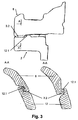
- the sliding caliper disc brake preferably has an approach on the sliding caliper or on the carrier on a corresponding contour on the carrier or on the Engages behind the sliding caliper and thereby the sliding caliper in Radially locked on the carrier, the axial Length of the neck or contour is such that the sliding saddle can be unlocked by axial displacement.
- Such a lock which advantageously be provided at least on the brake disc inlet side should guide the sliding saddle when reassembling the carrier. This is - approximately according to a bayonet lock - A particularly simple way of locking of the sliding saddle reached on the carrier.
- the guides are advantageously in accordance with the invention preferably arranged on the neck or the contour.
- the carrier can not be detached from the axis be connected. But it can also be detachably attached to the axis be.
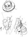
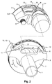
- FIGS. 1 and 2 show an axis 1 with one on it rigidly attached support 2 and a sliding saddle 3, to the Axial guide attached to the carrier along the brake axis Serve guide pin 4.
- the sliding saddle 3 is U-shaped, wherein an actuation-side saddle leg 5 a Bracing carries and against an actuating brake shoe 8 acts.
- a brake disc 7 mounted with a diameter D, the Direction of rotation R is indicated by an arrow.
- the carrier 2 has two on the actuation side in the radial direction not over the outer contour of the brake disc 7 extending arms with support surfaces 11.
- the distance A of the support surfaces 11 corresponds to the width of the actuation side Brake shoe 8.
- the support surfaces serve for lateral Support the brake shoe 8 and thus to initiate the Braking forces in the carrier 2.
- Reaction side extend in the radial direction two arms with support surfaces 12.
- the two Arms are - seen in axial projection - outside the brake disc contour arranged.
- the distance B between the support surfaces corresponds to the width C of the saddle leg on the reaction side 6.
- the support surfaces in turn serve as an introduction of braking forces in the carrier 2 by the reaction side Brake shoe 9 are transferred to the sliding caliper 3.
- the reaction-side brake shoe 9 In order to the reaction-side brake shoe 9 the braking forces on the Can transfer sliding saddle 3, it is on the side of the sliding saddle 3 supported. Support surfaces 9.1 on the reaction side serve this purpose Brake shoe 9 and support surfaces 3.3 on the sliding caliper 3. The support surfaces 3.3 are limited by the cutout 3.1 formed. For this reason, the neckline has 3.1 a width E, the width of the reaction-side brake shoe 9 corresponds.
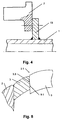
- Fig. 4 shows an embodiment in which the carrier 2 a support flange 13 welded to the axis 1 releasably attached is.
- screws can be used for fastening to serve.
- the brake shoes can either pulled out (in the radial direction) or moved apart (in the axial direction) become. Then the weight is removed from the Carrier 2 as previously described. Through the now freely accessible Opening area between the support surfaces 12 can Brake disc 7 removed from the axle without further dismantling of parts become.
Abstract
Description
Gleitsattel-Scheibenbremse für ein Landfahrzeug, mit einer Bremsscheibe, einem Gleitsattel, einem Träger, einer betätigungsseitigen Bremsbacke und einer reaktionsseitigen Bremsbacke, wobei der Träger unbeweglich bezüglich der Achse des Landfahrzeugs gehalten ist, die Bremsscheibe drehbar bezüglich der Achse gehalten ist und zur Montage/Demontage bezüglich des Trägers in Richtung der Achse verschieblich ist, der Gleitsattel zwei Schenkel hat, nämlich einen, der auf der Betätigungsseite der Bremsscheibe liegt, und einen, der auf der Reaktionsseite der Bremsscheibe liegt, der Träger sich axial von der Betätigungsseite zur Reaktionsseite der Bremsscheibe erstreckt, der Träger auf der Reaktionsseite eine lichte Weite hat, die derart bemessen ist, daß die Bremsscheibe beim Axialverschieben zur Montage/Demontage hindurchpaßt, und der Träger Führungen aufweist, auf denen der Gleitsattel gleitend geführt ist.Sliding caliper disc brake for a land vehicle, with a Brake disc, a sliding caliper, a carrier, one actuator-side brake shoe and a reaction-side Brake shoe, the carrier immobile with respect to the axis of the land vehicle is held, the brake disc rotatable with respect the axis is held and regarding assembly / disassembly the carrier is displaceable in the direction of the axis, the sliding caliper has two legs, namely one that is on the Actuating side of the brake disc, and one that is on is the reaction side of the brake disc, the carrier itself axially from the actuation side to the reaction side of the brake disc extends, the carrier on the reaction side has clear width, which is dimensioned such that the brake disc when moving axially for assembly / disassembly fits through, and the carrier has guides on which the Sliding caliper is slidably guided.
Die EP-A1-665 387 zeigt den Aufbau einer Gleitsattel-Scheibenbremse
und deren Befestigung an einer Achse 1. Die
beiden Sattelschenkel übergreifen U-förmig eine Bremsscheibe
12, um die beidseitig der Bremsscheibe in Führungsschächten
eines Gleitsattelträgers 14 gelagerten und abgestützten Bremsbacken
17 gegen die Bremsscheibe zu drücken. Der Gleitsattelträger
14 seinerseits ist an einem an der Achse 1 befestigten
Tragflansch 13 verschraubt. Wie insbesondere Fig. 6 der EP-A1-665
387 zu entnehmen ist, ist der Gleitsattelträger zur allflächigen
Führung der Bremsbacken geschlossen, d.h. daß er
rahmenartig die Bremsscheibe voll umgreift, vgl. auch EP-A1-665
387, Seite 2, Zeilen 55 und 56.EP-A1-665 387 shows the structure of a sliding caliper disc brake
and their attachment to an
Bei Gleitsattel-Scheibenbremsen dieser Bauart gestaltet
sich der Wechsel der Bremsscheibe als sehr umständlich,
weil der die Bremsscheibe voll umgreifende Gleitsattelträger
ein Entfernen der Bremsscheibe in Richtung der Reaktionsseite
der Bremse, die hier die Radfelgenseite ist, nicht ermöglicht.
Um dies nach dem Abbau der Radfelge zu realisieren, wird in
der EP-A1-665 387 vorgeschlagen, den Gleitsattelträger bis auf
eine Befestigungsschraube 15 vom Tragflansch 13 zu lösen und
die komplette Bremse über den Scheibenumfang hinaus
auszuschwenken.Designed for sliding caliper disc brakes of this type
changing the brake disc is very cumbersome,
because the sliding calliper carrier fully encompasses the brake disc
a removal of the brake disc in the direction of the reaction side
the brake, which is the wheel rim side here, is not possible.
To achieve this after dismantling the wheel rim, in
EP-A1-665 387 proposed the sliding caliper up to
to loosen a fastening screw 15 from the
Nachteilig bei dieser Lösung ist es zum einen, daß mehrere Befestigungsschrauben zu entfernen sind. Ferner liegt der Schwenkpunkt um die genannte Befestigungsschraube über dem Außendurchmesser der Bremsscheibe und weit oberhalb der Rotationskontur des Bremssattels im Bereich der Radfelge. Wenngleich diese Lösung mithin zwar für eine ganz spezielle Achsenkonstruktion mit dem für diese Ausführung zur Verfügung stehenden Einbauraum einsetzbar ist, ist sie jedoch allgemein nicht brauchbar. Denn sowohl die axialen als auch die radialen Platzverhältnisse im Bereich der Radführung mit der Bremsenbefestigung sind im allgemeinen derart beengt, daß entweder die Radfelge selbst oder andere Fahrzeugteile beim Verschwenken an den Tragflansch anschlagen könnten.One disadvantage of this solution is that several fastening screws have to be removed. Further lies the pivot point about the fixing screw above the Outside diameter of the brake disc and far above the rotation contour the brake caliper in the area of the wheel rim. Although this solution therefore for a very special one Axle construction with the available for this version standing installation space, it is general not usable. Because both the axial and the radial Space in the area of the wheel guide with the brake attachment are generally so cramped that either Wheel rim itself or other vehicle parts when swiveling could strike the support flange.
Aus der DE-A-40 36 272 ist eine weitere Gleitsattel-Scheibenbremse bekannt. Sie weist einen ebenfalls rahmenartigen Gleitsattelträger auf, der an die Achse angeschweißt ist. Da ein komplettes Ausschwenken der Bremse bei dieser Lösung nicht möglich ist, besteht der Gleitsattelträger aus zwei Teilen, die auf der Betätigungsseite miteinander verschraubt sind. Auch diese Lösung erfordert für einen Wechsel der Bremsscheibe mehrere Arbeitsschritte. Zuerst müssen die Bremsbacken entfernt, der Gleitsattel vom Gleitsattelträger gelöst und das die Bremsscheibe übergreifende Trägerteil von dem an der Achse angeschweißten Trägerteil getrennt werden. Erst danach ist der freie Zugang von der Felgenseite zur Bremsscheibe gegeben.DE-A-40 36 272 is a further sliding caliper disc brake known. It also has a frame-like one Sliding caliper carrier, which is welded to the axle. Because a complete swing out of the brake with this solution is not possible, the sliding saddle carrier consists of two parts, which are screwed together on the actuation side are. This solution also requires changing the brake disc several work steps. First the brake shoes removed, the sliding caliper detached from the sliding caliper carrier and that the support part overlapping the brake disc from that on the axle welded support part can be separated. Only then is that free access from the rim side to the brake disc.
Bei den beiden oben beschriebenen bekannten Bremsen handelt es sich jeweils um Nutzfahrzeugbremsen, die ein dementsprechend vergleichsweise großes Gewicht haben. Auch haben ihre einzelnen Bauteile ein erhebliches Gewicht, weshalb jeder zusätzliche Arbeitsschritt als nachteilig anzusehen ist.In the two known brakes described above each is a commercial vehicle brake, which is a corresponding have a comparatively large weight. Also have their individual components have a significant weight, which is why everyone additional work step is to be regarded as disadvantageous.
Aus der DE-C3-28 04 808 ist eine Gleitsattel-Scheibenbremse für PKW bekannt. Dabei umgreift der Gleitsattelträger nicht vollständig als Rahmen die Bremsscheibe. Jedoch hintergreifen zur Belagführung dienende Trägerarme auch soweit die Bremsscheibe, daß diese nur dann zugänglich ist, wenn die komplette Bremse von der Achse abgenommen ist. Bei einem mit der Achse eine integrierte Einheit bildenden Gleitsattelträger ist ein Scheibenwechsel somit überhaupt nicht möglich. DE-C3-28 04 808 is a sliding caliper disc brake known for cars. The sliding caliper supports not completely as a frame the brake disc. However reach behind support arms for covering guidance as far the brake disc that this is only accessible when the complete brake is removed from the axle. With one with the axle forms an integrated unit a disc change is not possible at all.
Die DE-C2-29 19 548 zeigt eine Gleitsattel-Scheibenbremse
der eingangs genannten Art. Bei dieser Ausführung weist
eine reaktionsseitige Bremsbacke Nuten 33L und 33R auf, in
die Führungsleisten 30L und 30R eines Trägers 11 eingreifen.
Dadurch ist die reaktionsseitige Bremsbacke in Radialrichtung
an dem Träger festgelegt. Soll die Bremsscheibe gewechselt
werden, muß nicht nur der Gleitsattel in Radialrichtung abgehoben
werden, sondern es muß auch zumindest die reaktionsseitige
Bremsbacke in Axialrichtung vom Träger abgezogen werden.
Erst dann liegt die Bremsscheibe derart frei, daß sie von der
Reaktionsseite her abgezogen werden kann.DE-C2-29 19 548 shows a sliding caliper disc brake
of the type mentioned in the introduction
a reaction-side brake shoe grooves 33L and 33R on, in
the guide strips 30L and 30R of a
Der Erfindung liegt die Aufgabe zugrunde, die Gleitsattel-Scheibenbremse nach der DE-C2-29 19 548 derart weiterzubilden, daß - auch im Hinblick auf die sehr beengten Einbauverhältnisse in Radführungen - der Arbeitsaufwand zum Montieren/Demontieren der Bremsscheibe minimiert wird.The invention has for its object the sliding caliper disc brake to further develop according to DE-C2-29 19 548, that - also in view of the very cramped installation conditions in wheel guides - the work involved in assembling / disassembling the brake disc is minimized.
Erfindungsgemäß wird die gestellte Aufgabe dadurch gelöst, daß die reaktionsseitige Bremsbacke in Radialrichtung an dem Gleitsattel festgelegt ist und zusammen mit dem Gleitsattel in Radialrichtung über den Außenumfang der Bremsscheibe hinaus von dem Träger abgehoben werden kann.According to the invention, the object is achieved in that that the reaction-side brake shoe in the radial direction the sliding saddle is fixed and together with the sliding saddle in the radial direction over the outer circumference of the brake disc can also be lifted off the carrier.
Mit anderen Worten dient erfindungsgemäß der Gleitsattel und nicht der Träger zur Radialfestlegung der reaktionsseitigen Bremsbacke. Daher sind auch keine eigenen Arbeitsschritte erforderlich, um die reaktionsseitige Bremsbacke zu demontieren. Vielmehr genügt das Abheben des Gleitsattels - und damit der daran festgelegten Bremsbacke - von dem Träger um die Bremsscheibe für die Montage/Demontage von der Reaktionsseite her freizulegen.In other words, the sliding caliper is used according to the invention and not the carrier for the radial determination of the reaction side Brake shoe. Therefore, there are no separate work steps required to close the reaction brake shoe disassemble. Rather, lifting the sliding saddle is enough - and thus the brake shoe attached to it - from the carrier around the brake disc for assembly / disassembly from the reaction side to expose her.
Erfindungsgemäß bevorzugt ist vorgesehen, daß der Träger zwei Arme aufweist, die sich axial von der Betätigungsseite zur Reaktionsseite erstrecken und auf ihrer bremsscheibenzugewandten Seite erste Stützflächen zur gleitenden Führung und Abstützung des Gleitsattels aufweisen, und daß der Gleitsattel mit einer Außenkontur an den Stützflächen anliegt. Mithin wirken die beiden Arme des Trägers derart mit dem Gleitsattel zusammen, daß sie die Bremskräfte (zumindest teilweise) aufnehmen können.According to the invention, it is preferably provided that the carrier has two arms that extend axially from the actuation side extend to the reaction side and face the brake disc Side first support surfaces for sliding guidance and support the sliding saddle, and that the sliding saddle lies with an outer contour on the support surfaces. The two arms of the wearer thus act with the Sliding caliper together so that they brake (at least partially) be able to record.
Die reaktionsseitige Bremsbacke wird sich beim Bremsen nicht in Axialrichtung bezüglich des Gleitsattels verschieben. Erfindungsgemäß stützt sich die reaktionsseitige Bremsbacke daher erfindungsgemäß bevorzugt in Tangentialrichtung an dem Gleitsattel ab. Durch diese Ausgestaltung wird erreicht, daß der Gleitsattel und die reaktionsseitige Bremsbacke noch weiter zu einer als Ganzes von dem Träger abnehmbaren Baueinheit zusammenwachsen. Darüber hinaus muß beim Einbau der Baueinheit aus reaktionsseitiger Bremsbacke und Gleitsattel nicht darauf geachtet werden, daß die reaktionsseitige Bremsbacke auch korrekt auf einer etwaig an dem Träger vorhandenen Führung sitzt. Vielmehr ist eine solche Führung am Träger im Hinblick auf die Abstützung der reaktionsseitigen Bremsbacke an dem Gleitsattel entbehrlich.The reaction-side brake shoe will turn when braking do not move in the axial direction with respect to the sliding saddle. According to the reaction-side brake shoe is supported therefore preferably according to the invention in the tangential direction Sliding caliper from. This configuration ensures that the sliding caliper and the reaction-side brake shoe even further to a unit which can be removed as a whole from the carrier grow together. In addition, when installing the unit from the reaction-side brake shoe and sliding caliper not on it care must be taken that the brake shoe on the reaction side is also correct sits on a guide possibly present on the carrier. Rather, such guidance is on the wearer with regard to the Support of the reaction-side brake shoe on the sliding caliper dispensable.
Weiter bevorzugt weist der Gleitsattel einen Ausschnitt zur Aufnahme der reaktionsseitigen Bremsbacke auf. Mit anderen Worten ist die reaktionsseitige Bremsbacke einfach in den Ausschnitt "eingesteckt", was ihre Montage/Demontage besonders einfach macht.The sliding caliper further preferably has a cutout to accommodate the brake shoe on the reaction side. With in other words, the brake shoe on the reaction side is simply in the cutout "inserted" what their assembly / disassembly particularly just do it.
Als den Gesamtaufbau weiter vereinfachend wird es erfindungsgemäß bevorzugt, daß Begrenzungen des Ausschnitts als zweite Stützflächen für die reaktionsseitige Bremsbacke dienen. Mit anderen Worten ist der Ausschnitt und damit die Abstützung der reaktionsseitigen Bremsbacke in Radialrichtung offen. As a further simplification of the overall structure, it is invented preferred that boundaries of the section as second support surfaces are used for the brake shoe on the reaction side. In other words, the cutout and thus the support the reaction-side brake shoe in the radial direction open.
Der Ausschnitt kann erfindungsgemäß auch zur Aufnahme der betätigungsseitigen Bremsbacke dienen. Damit wird weiter das Prinzip der in Radialrichtung offenen Gestaltung verfolgt.According to the invention, the section can also be used for recording serve the brake shoe on the actuating side. This continues follows the principle of the open design in the radial direction.
Bevorzugt stützt sich die betätigungsseitige Bremsbacke gleitend an dritten Stützflächen an dem Träger ab. Insbesondere dann, wenn der Ausschnitt auch die betätigungsseitige Bremsbacke aufnimmt, werden auch die dritten Stützflächen eine in Radialrichtung offene Ausgestaltung haben.The actuation-side brake shoe is preferably supported sliding on third support surfaces on the carrier. Especially then when the cutout also the actuation side Brake shoe, the third support surfaces have an open design in the radial direction.
Erfindungsgemäß bevorzugt ist eine Halteeinrichtung vorgesehen, die die betätigungsseitige Bremsbacke und die reaktionsseitige Bremsbacke in Radialrichtung an dem Gleitsattel festlegt. Damit muß nur ein Bauteil gelöst werden, um beide Bremsbacken freizugeben.A holding device is preferred according to the invention provided that the actuator-side brake shoe and the reaction-side brake shoe in the radial direction on the sliding caliper specifies. This means that only one component has to be released release both brake shoes.
Erfindungsgemäß bevorzugt weist die Gleitsattel-Scheibenbremse einen Ansatz an dem Gleitsattel oder an dem Träger auf, der eine entsprechende Kontur an dem Träger bzw. an dem Gleitsattel hintergreift und dadurch den Gleitsattel in Radialrichtung an dem Träger verriegelt, wobei die axiale Länge des Ansatzes oder der Kontur derart ist, daß der Gleitsattel durch Axialverschiebung entriegelt werden kann.According to the invention, the sliding caliper disc brake preferably has an approach on the sliding caliper or on the carrier on a corresponding contour on the carrier or on the Engages behind the sliding caliper and thereby the sliding caliper in Radially locked on the carrier, the axial Length of the neck or contour is such that the sliding saddle can be unlocked by axial displacement.
Eine solche Verriegelung, die vorteilhafterweise zumindest auf der Bremsscheibeneinlaufseite vorgesehen sein sollte, dient der Führung des Gleitsattels beim Wiederanbau an den Träger. Damit wird - etwa entsprechend einem Bajonettverschluß - eine besonders einfache Möglichkeit der Verriegelung des Gleitsattels an dem Träger erreicht.Such a lock, which advantageously be provided at least on the brake disc inlet side should guide the sliding saddle when reassembling the carrier. This is - approximately according to a bayonet lock - A particularly simple way of locking of the sliding saddle reached on the carrier.
Vorteilhafterweise sind die Führungen erfindungsgemäß bevorzugt an dem Ansatz oder der Kontur angeordnet. The guides are advantageously in accordance with the invention preferably arranged on the neck or the contour.
Erfindungsgemäß kann der Träger unlösbar mit der Achse verbunden sein. Er kann aber auch lösbar an der Achse angebracht sein.According to the invention, the carrier can not be detached from the axis be connected. But it can also be detachably attached to the axis be.
Im folgenden ist die Erfindung anhand bevorzugter Ausführungsbeispiele
unter Bezugnahme die beiliegende Zeichnung
mit weiteren Einzelheiten näher erläutert. Dabei zeigen
Die Fig. 1 und 2 zeigen eine Achse 1 mit einem daran
starr befestigten Träger 2 und einem Gleitsattel 3, zu dessen
Axialführung entlang der Bremsenachse am Träger befestigte
Führungsbolzen 4 dienen. Der Gleitsattel 3 ist U-förmig ausgebildet,
wobei ein betätigungsseitiger Sattelschenkel 5 eine
Zuspannung trägt und gegen eine betätigungsseitige Bremsbacke
8 wirkt. Ein reaktionsseitiger Sattelschenkel 6 hingegen, der
bei diesem Ausführungsbeispiel in Richtung der Radfelge zeigt,
wirkt gegen eine reaktionsseitige Bremsbacke 9 und weist eine
Breite C auf. Zwischen den Sattelschenkeln und dem Bremsbacken
ist eine Bremsscheibe 7 mit einem Durchmesser D gelagert, deren
Drehrichtung R durch einen Pfeil angedeutet ist.1 and 2 show an
In einem Ausschnitt 3.1 des Gleitsattels 3 sind beide
Bremsbacken 8, 9 mittels eines von dem Gleitsattel 3 lösbaren
Haltemittels 10 derart gehalten, daß sie zwar in Axialrichtung
der Bremsscheibe 7 beweglich, jedoch bezüglich anderer Richtungen
von dem genannten Haltemittel 10 festgelegt sind.In a section 3.1 of the sliding
Der Träger 2 weist betätigungsseitig zwei sich in Radialrichtung
nicht über die Außenkontur der Bremsscheibe 7
hinaus erstreckende Arme mit Stützflächen 11 auf. Der Abstand
A der Stützflächen 11 entspricht der Breite der betätigungsseitigen
Bremsbacke 8. Die Stützflächen dienen zur seitlichen
Abstützung der Bremsbacke 8 und damit zur Einleitung der
Bremskräfte in den Träger 2. Reaktionsseitig erstrecken sich
in Radialrichtung zwei Arme mit Stützflächen 12. Die beiden
Arme sind - in Axialprojektion gesehen - außerhalb der Bremsscheibenkontur
angeordnet. Der Abstand B der Stützflächen voneinander
entspricht der Breite C des reaktionsseitigen Sattelschenkels
6. Die Stützflächen dienen wiederum der Einleitung
von Bremskräften in den Träger 2, die von der reaktionsseitigen
Bremsbacke 9 auf den Gleitsattel 3 übertragen werden. Damit
die reaktionsseitige Bremsbacke 9 die Bremskräfte auf den
Gleitsattel 3 übertragen kann, ist sie seitlich an dem Gleitsattel
3 abgestützt. Dazu dienen Stützflächen 9.1 an der reaktionsseitigen
Bremsbacke 9 und Stützflächen 3.3 an dem Gleitsattel
3. Die Stützflächen 3.3 sind von Begrenzungen des Ausschnitts
3.1 gebildet. Aus diesem Grunde hat der Ausschnitt
3.1 eine Breite E, die der Breite der reaktionsseitigen Bremsbacke
9 entspricht.The
Um den Gleitsattel 3 in Radialrichtung auswärts festzulegen,
übergreift gemäß Fig. 3 zumindest auf einer Bremsscheibeneinlaufseite
eine Axialführung des Trägers 2 im Bereich
der reaktionsseitigen Stützfläche 12.1 einem Bereich 3.2
des reaktionsseitigen Sattelschenkels 6. Die einander übergreifenden
Abschnitte des reaktionsseitigen Sattelschenkels 6
einerseits und des Trägers 2 andererseits sind in ihrer axialen
Länge derart bemessen, daß der Gleitsattel 3 durch Axialverschiebung
bezüglich des Trägers 2 ver- bzw. entriegelt werden
kann.In order to fix the sliding
Fig. 4 zeigt eine Ausführung, bei der der Träger 2 an
einem an der Achse 1 angeschweißten Tragflansch 13 lösbar befestigt
ist. Zur Befestigung können beispielsweise Schrauben
dienen.Fig. 4 shows an embodiment in which the carrier 2
a
Mit der erfindungsgemäßen Ausgestaltung ist der reaktionsseitig
freie Zugang zur Bremsscheibe 7 mit wenigen
Arbeitsschritten realisierbar. Trotzdem ist eine gleichmäßige
Führung des Gleitsattels 3 und der Bremsbacken 8, 9 bezüglich
des Trägers 2 gewährleistet. Die Demontage erfolgt folgendermaßen:
Nachdem in herkömmlicher Weise die Radfelge, die Radnabe
etc. von der Achse 1 entfernt worden sind, werden zum
Ausbau der Bremsscheibe 7 zunächst die Führungsbolzen 4 von
dem Träger 2 gelöst. Danach kann der Gleitsattel 3 mit den
daran durch die Haltemittel 10 befestigten Bremsbacken 8, 9 in
einem einzigen Arbeitsschritt über den Durchmesser D der
Bremsscheibe 7 radial von dem Träger 2 abgehoben werden. Ist
zusätzlich eine Kopplung nach Fig. 3 vorhanden, muß der Gleitsattel
3 lediglich zunächst in Axialrichtung verschoben werden,
bis die Verriegelung in Radialrichtung aufgehoben ist. Um
die Axialverschiebung des Gleitsattels 3 zu ermöglichen, muß
im Inneren des Gleitsattels 3 entsprechend Platz geschaffen
werden. Dazu können beispielsweise die Bremsbacken entweder
(in Radialrichtung) herausgezogen oder (in Axialrichtung) auseinandergefahren
werden. Danach erfolgt das Abnehmen von dem
Träger 2 wie vorher beschrieben. Durch den jetzt frei zugänglichen
Öffnungsbereich zwischen den Stützflächen 12 kann die
Bremsscheibe 7 ohne weiteren Teileabbau von der Achse abgezogen
werden.With the configuration according to the invention, this is reaction-side
free access to the
Die in der vorstehenden Beschreibung, den Ansprüchen sowie der Zeichnung offenbarten Merkmale der Erfindung können sowohl einzeln als auch in beliebigen Kombinationen zur Verwirklichung der Erfindung in ihren verschiedenen Ausführungsformen wesentlich sein.The in the above description, the claims and the drawing disclosed features of the invention both individually and in any combination for realization of the invention in its various embodiments be essential.
Claims (12)
dadurch gekennzeichnet, daß
characterized in that
Applications Claiming Priority (2)
| Application Number | Priority Date | Filing Date | Title |
|---|---|---|---|
| DE19743538 | 1997-10-01 | ||
| DE19743538A DE19743538A1 (en) | 1997-10-01 | 1997-10-01 | Sliding caliper disc brake |
Publications (4)
| Publication Number | Publication Date |
|---|---|
| EP0906856A2 true EP0906856A2 (en) | 1999-04-07 |
| EP0906856A3 EP0906856A3 (en) | 2001-11-07 |
| EP0906856B1 EP0906856B1 (en) | 2003-07-30 |
| EP0906856B2 EP0906856B2 (en) | 2007-08-22 |
Family
ID=7844372
Family Applications (1)
| Application Number | Title | Priority Date | Filing Date |
|---|---|---|---|
| EP98118564A Expired - Lifetime EP0906856B2 (en) | 1997-10-01 | 1998-10-01 | Sliding caliper disc brake |
Country Status (2)
| Country | Link |
|---|---|
| EP (1) | EP0906856B2 (en) |
| DE (2) | DE19743538A1 (en) |
Cited By (4)
| Publication number | Priority date | Publication date | Assignee | Title |
|---|---|---|---|---|
| EP1293405A3 (en) * | 2001-08-29 | 2003-08-27 | Meritor Heavy Vehicle Braking Systems (UK) Limited | Axle assembly |
| US6820884B2 (en) | 2001-08-29 | 2004-11-23 | Meritor Heavy Vehicle Braking Systems | Integrated axle adaptor and spring seat for a vehicle suspension system |
| EP1610025A1 (en) | 2004-06-24 | 2005-12-28 | Meritor Heavy Vehicle Braking Systems (UK) Limited | Disc brake assembly |
| DE102006002569A1 (en) * | 2006-01-18 | 2007-07-19 | Bpw Bergische Achsen Kg | disc brake |
Families Citing this family (8)
| Publication number | Priority date | Publication date | Assignee | Title |
|---|---|---|---|---|
| DE19823034C1 (en) * | 1998-05-22 | 1999-12-02 | Wabco Perrot Bremsen Gmbh | Disc brake for a land vehicle |
| DE19857074B4 (en) * | 1998-12-10 | 2009-08-06 | Knorr-Bremse Systeme für Nutzfahrzeuge GmbH | Pneumatic disc brake and brake carrier |
| DE10241157A1 (en) * | 2002-09-05 | 2004-03-25 | Wabco Perrot Bremsen Gmbh | disc brake |
| DE102004009123B4 (en) | 2004-03-01 | 2007-06-14 | Wabco Radbremsen Gmbh | disc brake |
| DE102007024578B3 (en) * | 2007-05-25 | 2008-11-06 | Wabco Radbremsen Gmbh | Disk brake for commercial vehicle, has rim sided brake pad decoupled from brake carrier in radial direction of brake disk, and rail is provided at rim-sided side piece of brake caliper for supporting rim-sided brake pad in radial direction |
| WO2012082020A1 (en) | 2010-12-15 | 2012-06-21 | Volvo Lastvagnar Ab | Steering knuckle and vehicle comprising a steering knuckle |
| DE202013101406U1 (en) | 2013-04-02 | 2013-05-06 | Haldex Brake Products Ab | disc brake |
| DE102020114659A1 (en) | 2020-06-02 | 2021-12-02 | Mann+Hummel Gmbh | Brake caliper device, disc brake assembly, use of a brake caliper device and method for radial retention of air |
Citations (4)
| Publication number | Priority date | Publication date | Assignee | Title |
|---|---|---|---|---|
| DE2919548C2 (en) | 1978-08-01 | 1987-03-19 | Kelsey-Hayes Co., Romulus, Mich., Us | |
| DE2804808C3 (en) | 1978-02-04 | 1988-09-29 | Alfred Teves Gmbh, 6000 Frankfurt, De | |
| DE4036272A1 (en) | 1990-11-14 | 1992-05-21 | Perrot Bremse Gmbh Deutsche | Saddle type disc brake with brake support - has brake disco around which grip two arms of brake saddle, with hydraulic or mechanical control |
| EP0665387A1 (en) | 1994-02-01 | 1995-08-02 | BPW Bergische Achsen Kommanditgesellschaft | Disc brake |
Family Cites Families (11)
| Publication number | Priority date | Publication date | Assignee | Title |
|---|---|---|---|---|
| DE2807125C2 (en) † | 1978-02-20 | 1986-06-26 | Alfred Teves Gmbh, 6000 Frankfurt | Floating-caliper partially lined disc brakes, in particular for motor vehicles |
| US4319668A (en) † | 1979-12-26 | 1982-03-16 | Eaton Corporation | Push-pull caliper |
| US4418798A (en) † | 1980-09-29 | 1983-12-06 | The Bendix Corporation | Disc brake with wedge pins |
| US4440267A (en) † | 1981-10-26 | 1984-04-03 | Kelsey Hayes Company | Disc brake |
| FR2539196B1 (en) † | 1983-01-12 | 1986-02-28 | Dba | DISC BRAKE |
| US4609078A (en) † | 1983-11-30 | 1986-09-02 | Allied Corporation | Spring entrapment of split wedge floatation device |
| US4596318A (en) † | 1983-12-09 | 1986-06-24 | Ford Motor Company | Split shell caliper pin assembly and disc brake |
| DE3910969C2 (en) * | 1989-04-05 | 1994-09-01 | Teves Gmbh Alfred | Part-pad disc brake |
| AR245274A1 (en) * | 1989-08-11 | 1993-12-30 | Lucas Ind Plc | Spot-type disc brake |
| DE4027563A1 (en) * | 1990-08-31 | 1992-03-05 | Teves Gmbh Alfred | FLOATING SADDLE AND BRAKE PAD FOR PARTIAL DISC BRAKES |
| DE4334839A1 (en) * | 1993-10-13 | 1995-04-20 | Teves Gmbh Alfred | Floating-caliper disc brake |
-
1997
- 1997-10-01 DE DE19743538A patent/DE19743538A1/en not_active Withdrawn
-
1998
- 1998-10-01 DE DE59809144T patent/DE59809144D1/en not_active Expired - Lifetime
- 1998-10-01 EP EP98118564A patent/EP0906856B2/en not_active Expired - Lifetime
Patent Citations (4)
| Publication number | Priority date | Publication date | Assignee | Title |
|---|---|---|---|---|
| DE2804808C3 (en) | 1978-02-04 | 1988-09-29 | Alfred Teves Gmbh, 6000 Frankfurt, De | |
| DE2919548C2 (en) | 1978-08-01 | 1987-03-19 | Kelsey-Hayes Co., Romulus, Mich., Us | |
| DE4036272A1 (en) | 1990-11-14 | 1992-05-21 | Perrot Bremse Gmbh Deutsche | Saddle type disc brake with brake support - has brake disco around which grip two arms of brake saddle, with hydraulic or mechanical control |
| EP0665387A1 (en) | 1994-02-01 | 1995-08-02 | BPW Bergische Achsen Kommanditgesellschaft | Disc brake |
Cited By (5)
| Publication number | Priority date | Publication date | Assignee | Title |
|---|---|---|---|---|
| EP1293405A3 (en) * | 2001-08-29 | 2003-08-27 | Meritor Heavy Vehicle Braking Systems (UK) Limited | Axle assembly |
| US6820884B2 (en) | 2001-08-29 | 2004-11-23 | Meritor Heavy Vehicle Braking Systems | Integrated axle adaptor and spring seat for a vehicle suspension system |
| EP1610025A1 (en) | 2004-06-24 | 2005-12-28 | Meritor Heavy Vehicle Braking Systems (UK) Limited | Disc brake assembly |
| US7631733B2 (en) | 2004-06-24 | 2009-12-15 | Meritor Heavy Vehicle Braking Systems (Uk) Limited | Brake assembly |
| DE102006002569A1 (en) * | 2006-01-18 | 2007-07-19 | Bpw Bergische Achsen Kg | disc brake |
Also Published As
| Publication number | Publication date |
|---|---|
| EP0906856A3 (en) | 2001-11-07 |
| DE19743538A1 (en) | 1999-04-08 |
| EP0906856B2 (en) | 2007-08-22 |
| EP0906856B1 (en) | 2003-07-30 |
| DE59809144D1 (en) | 2003-09-04 |
Similar Documents
| Publication | Publication Date | Title |
|---|---|---|
| DE19652694C2 (en) | Arrangement of a brake disc on a wheel hub | |
| EP0906856B1 (en) | Sliding caliper disc brake | |
| DE10260597B4 (en) | Brake mechanism for a disc brake | |
| WO2017036763A1 (en) | Disc brake of a commercial vehicle | |
| DE2113946C3 (en) | Detachable connection between the brake caliper and the hydraulic cylinder of a partially lined disc brake | |
| DE2520768A1 (en) | DISC BRAKE AS WELL AS METHOD OF ASSEMBLY OF THE SAME | |
| EP0636217B1 (en) | Process for producing a brake disc for a disc brake | |
| DE3504055A1 (en) | CONSTRUCTION DRUM FOR TIRES | |
| DE602004013093T2 (en) | Aircraft brake assembly | |
| DE10241867A1 (en) | Disk brake unit in particular for heavy vehicle, comprising flange of brake disk joining torus attached to or integrated in wheel flange | |
| DE102004050349B4 (en) | Commercial vehicle disc brake | |
| DE19822606C1 (en) | Brake for motor vehicle wheel | |
| WO2007079770A1 (en) | Rotating device for vehicle axles in a painting installation | |
| DE1151276B (en) | Brake disc, especially for rail vehicles | |
| EP0959259A2 (en) | Disc brake for a land craft | |
| DE1605223B2 (en) | Air-cooled disc brakes, especially for railroad cars | |
| DE19823034C1 (en) | Disc brake for a land vehicle | |
| EP3238951A2 (en) | Hub and wheel | |
| DE19957484A1 (en) | Internally ventilated brake disk for high speed trains has air inlets and outlets with seating and cooperating seal which is raised above the seating, e.g. by thermal expansion, when temperature of disk rises | |
| DE2315134A1 (en) | RAILWAY WHEEL WITH BRAKE RING SEGMENTS | |
| EP0856679B1 (en) | Coupling device for connecting a hub to a brake disc | |
| DE3623762A1 (en) | Winding shaft for an awning | |
| DE2651539A1 (en) | DISC BRAKE FOR VEHICLES | |
| DE4402960A1 (en) | Disc brake | |
| DE2707554C2 (en) | Full-lined disc brake with a rotating brake housing |
Legal Events
| Date | Code | Title | Description |
|---|---|---|---|
| PUAI | Public reference made under article 153(3) epc to a published international application that has entered the european phase |
Free format text: ORIGINAL CODE: 0009012 |
|
| AK | Designated contracting states |
Kind code of ref document: A2 Designated state(s): AT BE CH CY DE DK ES FI FR GB GR IE IT LI LU MC NL PT SE Kind code of ref document: A2 Designated state(s): DE GB SE |
|
| AX | Request for extension of the european patent |
Free format text: AL;LT;LV;MK;RO;SI |
|
| PUAL | Search report despatched |
Free format text: ORIGINAL CODE: 0009013 |
|
| AK | Designated contracting states |
Kind code of ref document: A3 Designated state(s): AT BE CH CY DE DK ES FI FR GB GR IE IT LI LU MC NL PT SE |
|
| AX | Request for extension of the european patent |
Free format text: AL;LT;LV;MK;RO;SI |
|
| 17P | Request for examination filed |
Effective date: 20020506 |
|
| AKX | Designation fees paid |
Free format text: DE GB SE |
|
| 17Q | First examination report despatched |
Effective date: 20020701 |
|
| GRAH | Despatch of communication of intention to grant a patent |
Free format text: ORIGINAL CODE: EPIDOS IGRA |
|
| GRAH | Despatch of communication of intention to grant a patent |
Free format text: ORIGINAL CODE: EPIDOS IGRA |
|
| GRAA | (expected) grant |
Free format text: ORIGINAL CODE: 0009210 |
|
| AK | Designated contracting states |
Designated state(s): DE GB SE |
|
| REG | Reference to a national code |
Ref country code: GB Ref legal event code: FG4D Free format text: NOT ENGLISH |
|
| GBT | Gb: translation of ep patent filed (gb section 77(6)(a)/1977) |
Effective date: 20030730 |
|
| REF | Corresponds to: |
Ref document number: 59809144 Country of ref document: DE Date of ref document: 20030904 Kind code of ref document: P |
|
| REG | Reference to a national code |
Ref country code: SE Ref legal event code: TRGR |
|
| PLBQ | Unpublished change to opponent data |
Free format text: ORIGINAL CODE: EPIDOS OPPO |
|
| PLBI | Opposition filed |
Free format text: ORIGINAL CODE: 0009260 |
|
| PLAX | Notice of opposition and request to file observation + time limit sent |
Free format text: ORIGINAL CODE: EPIDOSNOBS2 |
|
| 26 | Opposition filed |
Opponent name: MICHAEL STANLEY MICHAEL STANLEY & CO Effective date: 20040430 |
|
| PLAX | Notice of opposition and request to file observation + time limit sent |
Free format text: ORIGINAL CODE: EPIDOSNOBS2 |
|
| PLBB | Reply of patent proprietor to notice(s) of opposition received |
Free format text: ORIGINAL CODE: EPIDOSNOBS3 |
|
| PUAH | Patent maintained in amended form |
Free format text: ORIGINAL CODE: 0009272 |
|
| STAA | Information on the status of an ep patent application or granted ep patent |
Free format text: STATUS: PATENT MAINTAINED AS AMENDED |
|
| 27A | Patent maintained in amended form |
Effective date: 20070822 |
|
| AK | Designated contracting states |
Kind code of ref document: B2 Designated state(s): DE GB SE |
|
| REG | Reference to a national code |
Ref country code: SE Ref legal event code: RPEO |
|
| GBTA | Gb: translation of amended ep patent filed (gb section 77(6)(b)/1977) | ||
| PGFP | Annual fee paid to national office [announced via postgrant information from national office to epo] |
Ref country code: GB Payment date: 20101022 Year of fee payment: 13 |
|
| PGFP | Annual fee paid to national office [announced via postgrant information from national office to epo] |
Ref country code: SE Payment date: 20111026 Year of fee payment: 14 |
|
| PGFP | Annual fee paid to national office [announced via postgrant information from national office to epo] |
Ref country code: DE Payment date: 20111223 Year of fee payment: 14 |
|
| GBPC | Gb: european patent ceased through non-payment of renewal fee |
Effective date: 20121001 |
|
| PG25 | Lapsed in a contracting state [announced via postgrant information from national office to epo] |
Ref country code: DE Free format text: LAPSE BECAUSE OF NON-PAYMENT OF DUE FEES Effective date: 20130501 Ref country code: SE Free format text: LAPSE BECAUSE OF NON-PAYMENT OF DUE FEES Effective date: 20121002 Ref country code: GB Free format text: LAPSE BECAUSE OF NON-PAYMENT OF DUE FEES Effective date: 20121001 |
|
| REG | Reference to a national code |
Ref country code: DE Ref legal event code: R119 Ref document number: 59809144 Country of ref document: DE Effective date: 20130501 |