EP0959259A2 - Disc brake for a land craft - Google Patents
Disc brake for a land craft Download PDFInfo
- Publication number
- EP0959259A2 EP0959259A2 EP99109957A EP99109957A EP0959259A2 EP 0959259 A2 EP0959259 A2 EP 0959259A2 EP 99109957 A EP99109957 A EP 99109957A EP 99109957 A EP99109957 A EP 99109957A EP 0959259 A2 EP0959259 A2 EP 0959259A2
- Authority
- EP
- European Patent Office
- Prior art keywords
- brake
- disc
- carrier
- pad
- lining
- Prior art date
- Legal status (The legal status is an assumption and is not a legal conclusion. Google has not performed a legal analysis and makes no representation as to the accuracy of the status listed.)
- Withdrawn
Links
Images


Classifications
-
- F—MECHANICAL ENGINEERING; LIGHTING; HEATING; WEAPONS; BLASTING
- F16—ENGINEERING ELEMENTS AND UNITS; GENERAL MEASURES FOR PRODUCING AND MAINTAINING EFFECTIVE FUNCTIONING OF MACHINES OR INSTALLATIONS; THERMAL INSULATION IN GENERAL
- F16D—COUPLINGS FOR TRANSMITTING ROTATION; CLUTCHES; BRAKES
- F16D55/00—Brakes with substantially-radial braking surfaces pressed together in axial direction, e.g. disc brakes
- F16D55/02—Brakes with substantially-radial braking surfaces pressed together in axial direction, e.g. disc brakes with axially-movable discs or pads pressed against axially-located rotating members
- F16D55/22—Brakes with substantially-radial braking surfaces pressed together in axial direction, e.g. disc brakes with axially-movable discs or pads pressed against axially-located rotating members by clamping an axially-located rotating disc between movable braking members, e.g. movable brake discs or brake pads
- F16D55/224—Brakes with substantially-radial braking surfaces pressed together in axial direction, e.g. disc brakes with axially-movable discs or pads pressed against axially-located rotating members by clamping an axially-located rotating disc between movable braking members, e.g. movable brake discs or brake pads with a common actuating member for the braking members
-
- F—MECHANICAL ENGINEERING; LIGHTING; HEATING; WEAPONS; BLASTING
- F16—ENGINEERING ELEMENTS AND UNITS; GENERAL MEASURES FOR PRODUCING AND MAINTAINING EFFECTIVE FUNCTIONING OF MACHINES OR INSTALLATIONS; THERMAL INSULATION IN GENERAL
- F16D—COUPLINGS FOR TRANSMITTING ROTATION; CLUTCHES; BRAKES
- F16D65/00—Parts or details
- F16D65/02—Braking members; Mounting thereof
- F16D65/04—Bands, shoes or pads; Pivots or supporting members therefor
- F16D65/092—Bands, shoes or pads; Pivots or supporting members therefor for axially-engaging brakes, e.g. disc brakes
-
- F—MECHANICAL ENGINEERING; LIGHTING; HEATING; WEAPONS; BLASTING
- F16—ENGINEERING ELEMENTS AND UNITS; GENERAL MEASURES FOR PRODUCING AND MAINTAINING EFFECTIVE FUNCTIONING OF MACHINES OR INSTALLATIONS; THERMAL INSULATION IN GENERAL
- F16D—COUPLINGS FOR TRANSMITTING ROTATION; CLUTCHES; BRAKES
- F16D55/00—Brakes with substantially-radial braking surfaces pressed together in axial direction, e.g. disc brakes
- F16D2055/0004—Parts or details of disc brakes
- F16D2055/0016—Brake calipers
- F16D2055/002—Brake calipers assembled from a plurality of parts
Definitions
- the invention relates to a disc brake for a land vehicle, with a brake disc, at least one brake pad, when the brake is actuated in a predetermined direction is pressed against the brake disc and at least one brake pad, who carries the brake pad directly and who at Brakes on the brake pad occurring friction forces.
- Disc brakes of the type mentioned are known for example from DE 39 06 450 A1. It is used as a topping in the sense of the invention only that in DE 39 06 450 A1 Support plate 1 shown viewed, but not any guide bolts in the brake caliper, to which the carrier plate by means of Slots 13 is suspended. These guide pins serve namely even wearing the brake pad, but wear it not “immediately”, as is the case with the carrier plate 1 is.
- Another object of the invention is a disc brake of the type mentioned above to design that when replacing a worn brake pad not also the pad carrier must be replaced.
- the object of the invention is an impairment the system of the brake pad on the brake disc when braking to avoid due to a deflection of the brake pad.
- the object is achieved in that that with a disc brake of the type mentioned the brake pad for braking with respect to the pad carrier in the predetermined direction is displaceable.
- the brake pad is used for braking the brake disc is pressed, but not the lining carrier.
- the clamping force acts on the brake pad, but not on the brake pad.
- the lining carrier preferably holds the brake lining in a parallel to the main plane of the brake disc lying level like a frame. This leaves an exact Receive guidance of the brake pad by the pad carrier even then when the brake disc and brake pad reach their wear limits have fallen below. In contrast, the disc brake the brake shoe according to the above-mentioned prior art fall out of their leadership when the wear limits were undercut.
- the brake pad is further preferred in a through opening arranged in the lining carrier.
- Words is a completely enclosing the brake pad Frame provided, which is a reliable mount and Guidance of the brake pad ensures.
- the passage opening allows the brake pad to be inserted from the side facing away from the disc Page ago.
- the through opening has a circular inner contour and the brake pad in Cross-section has a circular outer contour. This will make the Assembly / disassembly of the brake pad on the pad carrier especially simple.
- the covering carrier is preferably plate-shaped, resulting in an overall comparatively simple structure of the Disc brake results.
- the lining carrier immovable on the land vehicle in the predetermined direction is held.
- the brake pad can be detachably attached to the land vehicle be. If the brake pad is removed from the brake, it must be replaced the brake pad used in it is particularly simple.
- an elastic coupling device can be preferred provided on the lining carrier for the brake lining be. This will make the relative forward and backward movement of the Brake pad in the predetermined direction with respect to the pad carrier improved.
- the brake pad with an axis of rotation of the brake disc form an acute angle.
- the covering carrier can be used to carry two or more brake pads. This can cause the friction surface enlarged and therefore very variable according to the respective Use case to be designed. Gaps between neighboring brake pads leave a much better one Air circulation and thus an improved cooling function, causing damage to the brake pad and / or the brake disc can be prevented by overheating due to continuous braking can.
- sliding saddles of the radially open design how they are used in particular in commercial vehicles, a radial depending on the size of the braking force Widening.
- This elastic radial deformation occurs in particular on the reaction side saddle leg in the form of a Inclination on, which leads to the reaction-side Brake pad for a non-uniform contact pressure comes against the brake disc.
- edge pressures occur, radial oblique wear and excessive Brake disc load on, which then leads to heat cracks on the Can lead brake disc.
- This critical and a permanent load area on the sliding saddle subject to deformation the brake disc is always in the transition area from the two overlapping bridge areas in the radially inward running reaction-side caliper leg. Two such Areas are marked in FIG. 8 by dashed frames.
- Another disadvantage of the described embodiment lies in that it is only possible to change the brake disc if previously the brake caliper bolt guides from the brake carrier solved and then the overlapping the brake disc Sliding saddle has been completely removed. The expansion is accordingly cumbersome and time consuming.
- the disc brake has a sliding saddle which consists of at least two parts releasably connected together, wherein to connect the two parts at least one in the transition area between one radially outside the circumference the brake disc lying bridge area and the brake disc radially overlapping reaction caliper legs arranged connecting element, which is in Axial direction of the brake disc extends.
- One of the two parts preferably has the brake disc radially overlapping caliper legs.
- the fasteners for example formed by screws can be from the reaction side (open vehicle side) removed from the caliper leg of the Bridge area can be removed, giving free access is created from this side to the brake disc. So can without dismantling the other saddle parts, for example any Bolt guides, the brake disc below the bridge area to the open side of the vehicle.
- reaction side Brake caliper legs for example, made of one material higher strength, such as as a forged part the remaining saddle parts can be manufactured. This leaves the saddle dimensions have a positive influence.
- the brake caliper leg designed as an extra part, leaves also a much better and more flexible design and processing of the topping structure.
- the figures each show details of brakes in use the invention.
- the brakes can be caliper disc brakes, act in particular sliding caliper disc brakes.
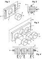
- Fig. 1 shows a plate-shaped, parallel to one Brake disc center plane S extending lining carrier 1 with an opening 3 into which a brake pad 2 of the same contour is inserted that it emerges on both sides from the lining carrier 1 protrudes and opposite this along a displacement axis A is movable. 2, the brake pad 2 is related of the brake pad carrier 1 when the brake pad 2 a clamping force Fz acts. The clamping force Fz presses the Brake pad 2 against a brake disc 7.
- Figures 3 and 4 show an embodiment in which more than just one brake pad 2, namely three brake pads in openings 3 of a lining carrier 1 are held displaceably.
- the figures show round openings and cylindrical brake pads with a circular cross-section, but be explicit on it noted that in addition to this proved to be the optimal form Designs also other shapes and contours individually or in combinations are possible if necessary should.
- the brake pad 2 a guide element 4.
- the guide element 4 deforms an elastic element 5, which between the guide element 4th and the lining carrier 1.
- the elastic element 5 it can be a spring or an elastomer.
- Fz application force
- FIG. 6b shows the associated with the brake pad carrier 1 elastic element 5 such in those areas on the circumference of the opening arranged that absorb no frictional forces that it when braking (Fig. 6a) not compressed, but only through lateral, i.e. essentially occurring in the axial direction Entrainment is deformed. The risk of crushing the elastic element 5 is banned in this way. Furthermore but the mode of operation is exactly like that after 5 and 5a.
- Fig. 7 shows that the lining carrier 1 firmly on the Braking force absorbing part 6 of the vehicle carrying the brake is attached, for example by (not shown) Screws.
- the elements 1 and 6 can also be in one piece be executed together. In other words, the same the fixed part 6, the opening 3 for receiving the brake pad 2 exhibit.
- the function of the disc brake according to the invention results itself from the above description of the exemplary embodiments.
- the assembly / disassembly of the brake pad 2 or more Brake pads in the corresponding openings 3 of the pad carrier 1 is very easy. A simple push into the opening 3 is enough. It can be done from the side facing away from the window. If the lining carrier is a rigid part, brake pads are exchanged immediately in the brake. However, if, for example, tight installation conditions are required make, the lining carrier 1 is removed from the fixed part 6, and the brake pad is exchanged outside the brake.
- a sliding caliper 20 is axially displaceable through bolt guides 21 on a brake carrier 22 (not shown) mounted and encompasses a brake disc 23 his two saddle legs.
- the bolt guides are located in the actuating side saddle leg 24, which is an actuating device having. Extend from this saddle leg over the outer circumference of the brake disc two Bridge struts 25, at the ends of which there is a reaction side Saddle leg 26 connects.
- actuating side saddle leg 24 Extend from this saddle leg over the outer circumference of the brake disc two Bridge struts 25, at the ends of which there is a reaction side Saddle leg 26 connects.
- connection profiles e.g. Claw profiles etc.
- connection profiles e.g. Claw profiles etc.
- reaction side Saddle leg 26 made of a material of higher strength, e.g. as a forged part compared to the other saddle parts 24, 25 can be produced. This allows the Saddle saddle influence positively.
- the saddle leg is available as an extra part 26 also a much better and more flexible design and machining of a lining system structure 32.
Abstract
Description
Die Erfindung betrifft eine Scheibenbremse für ein Landfahrzeuq, mit einer Bremsscheibe, mindestens einem Bremsbelag, der bei Betätigung der Bremse in einer vorbestimmten Richtung gegen die Bremsscheibe gedrückt wird, und mindestens einem Belagträger, der den Bremsbelag unmittelbar trägt und die beim Bremsen an dem Bremsbelag auftretenden Reibkräfte aufnimmt.The invention relates to a disc brake for a land vehicle, with a brake disc, at least one brake pad, when the brake is actuated in a predetermined direction is pressed against the brake disc and at least one brake pad, who carries the brake pad directly and who at Brakes on the brake pad occurring friction forces.
Scheibenbremsen der eingangs genannten Art sind bekannt,
beispielsweise aus der DE 39 06 450 A1. Dabei wird als Belagträger
im Sinne der Erfindung nur die in der DE 39 06 450 A1
gezeigte Trägerplatte 1 angesehen, nicht aber etwaige Führungsbolzen
im Bremssattel, an denen die Trägerplatte mittels
Schlitzen 13 aufgehängt ist. Diese Führungsbolzen dienen nämlich
zwar auch dem Tragen des Bremsbelags, tragen ihn aber
nicht "unmittelbar", wie das bei der Trägerplatte 1 der Fall
ist.Disc brakes of the type mentioned are known
for example from DE 39 06 450 A1. It is used as a topping
in the sense of the invention only that in DE 39 06 450 A1
Nach der DE 39 06 450 A1 bilden der Bremsbelag und der Belagträger zusammen die sogenannte Bremsbacke. Dabei ist der Bremsbelag durch heißes Aufpressen an der Trägerplatte unlösbar befestigt. Mithin kann beim Betätigen der Bremse der Bremsbelag nur gemeinsam mit dem Belagträger gegen die Bremsscheibe gedrückt werden, weshalb der Belagträger auch entsprechend verschieblich an dem Bremsenträger gehalten sein muß.According to DE 39 06 450 A1 form the brake pad and Pad carrier together the so-called brake shoe. Here is the Brake lining cannot be removed by hot pressing on the carrier plate attached. Thus, when the brake is applied, the Brake pad only together with the pad carrier against the brake disc are pressed, which is why the brake pad is also appropriate must be slidably held on the brake carrier.
Die Herstellung der aus dem Stand der Technik bekannten Bremsbacke ist sehr aufwendig. Darüber hinaus muß bei Erreichen der Verschleißgrenze nicht nur der Bremsbelag, sondern auch der Belagträger ausgetauscht werden, was äußerst unwirtschaftlich ist. Schließlich wird bei Bremsen des Standes der Technik immer wieder eine Durchbiegung des Belagträgers beobachtet, die sich wegen dessen fester Verbindung mit dem Bremsbelag auch auf den Bremsbelag auswirkt, so daß keine optimale Anlage an der Bremsscheibe mehr gegeben ist.The production of those known from the prior art Brake shoe is very complex. In addition, must be reached the wear limit not just the brake pad, but also the brake pad can be replaced, which is extremely uneconomical is. Finally, when braking the state of the Technology repeatedly observed a deflection of the brake pad, which is because of its firm connection with the brake pad also affects the brake pad, so that no optimal System on the brake disc is more.
Es ist Aufgabe der Erfindung, die Herstellung einer Scheibenbremse zu vereinfachen. Ferner ist Aufgabe der Erfindung, eine Scheibenbremse der eingangs genannten Art derart auszugestalten, daß beim Austausch eines verschlissenen Bremsbelags nicht auch der Belagträger mit ausgetauscht werden muß. Schließlich ist Aufgabe der Erfindung, eine Beeinträchtigung der Anlage des Bremsbelages an der Bremsscheibe beim Bremsen infolge eines Durchbiegens des Belagträgers zu vermeiden.It is an object of the invention to produce a Simplify disc brake. Another object of the invention is a disc brake of the type mentioned above to design that when replacing a worn brake pad not also the pad carrier must be replaced. Finally, the object of the invention is an impairment the system of the brake pad on the brake disc when braking to avoid due to a deflection of the brake pad.
Erfindungsgemäß wird die gestellte Aufgabe dadurch gelöst, daß bei einer Scheibenbremse der eingangs genannten Art der Bremsbelag zum Bremsen bezüglich des Belagträgers in der vorbestimmten Richtung verschieblich ist. According to the invention, the object is achieved in that that with a disc brake of the type mentioned the brake pad for braking with respect to the pad carrier in the predetermined direction is displaceable.
Mit anderen Worten wird zum Bremsen der Bremsbelag gegen die Bremsscheibe gedrückt, nicht aber der Belagträger. Die Zuspannkraft wirkt dazu zwar auf den Bremsbelag, nicht aber auf den Belagträger.In other words, the brake pad is used for braking the brake disc is pressed, but not the lining carrier. The clamping force acts on the brake pad, but not on the brake pad.
Da keine dauerhafte Befestigung des Bremsbelages an dem Belagträger erforderlich ist, ist die Herstellung insgesamt vereinfacht. Ferner kann der Bremsbelag bei Erreichen seiner Verschleißgrenze ausgetauscht werden, ohne daß es auch gleichzeitig eines Austauschs des Belagträgers bedürfte. Schließlich wirkt sich wegen der Verschieblichkeit des Bremsbelages bezüglich des Belagträgers eine eventuelle Durchbiegung des Belagträgers nicht auf die Anlage des Bremsbelages an der Bremsscheibe beim Bremsen aus. Abgesehen davon wird wegen der genannten Verschieblichkeit bei einer erfindungsgemäßen Scheibenbremse eine Zuspannkraft immer direkt auf den Bremsbelag und nicht auf den Belagträger wirken, weshalb eine Durchbiegung des Belagträgers schon aus diesem Grunde nicht zu erwarten ist.Since there is no permanent attachment of the brake pad to the Covering is required, the production is total simplified. Furthermore, the brake pad when it reaches Wear limit can be replaced without it at the same time an exchange of the brake pad would be necessary. Finally affects due to the displaceability of the brake pad a possible deflection of the brake pad not on the contact of the brake pad on the brake disc when braking. Apart from that, because of the above Movability in a disc brake according to the invention an application force always directly on the brake pad and do not act on the lining carrier, which is why a deflection of the brake pad cannot be expected for this reason alone is.
Erfindungsgemäß bevorzugt faßt der Belagträger den Bremsbelag in einer parallel zu der Hauptebene der Bremsscheibe liegenden Ebene rahmenartig ein. Dadurch bleibt eine exakte Führung des Bremsbelages durch den Belagträger selbst dann erhalten, wenn Bremsscheibe und Bremsbelag ihre Verschleißgrenzen unterschritten haben. Demgegenüber konnte bei der Scheibenbremse nach dem oben genannten Stand der Technik die Bremsbacke aus ihrer Führung herausfallen, wenn die Verschleißgrenzen unterschritten wurden.According to the invention, the lining carrier preferably holds the brake lining in a parallel to the main plane of the brake disc lying level like a frame. This leaves an exact Receive guidance of the brake pad by the pad carrier even then when the brake disc and brake pad reach their wear limits have fallen below. In contrast, the disc brake the brake shoe according to the above-mentioned prior art fall out of their leadership when the wear limits were undercut.
Der Bremsbelag ist erfindungsgemäß weiter bevorzugt in einer Durchgangsöffnung in dem Belagträger angeordnet. Mit anderen Worten ist ein den Bremsbelag vollständig umschließender Rahmen vorgesehen, der eine allseits verläßliche Halterung und Führung des Bremsbelages sicherstellt. Die Durchgangsöffnung erlaubt dabei ein Einsetzen des Bremsbelages von der scheibenabgewandten Seite her.According to the invention, the brake pad is further preferred in a through opening arranged in the lining carrier. With others Words is a completely enclosing the brake pad Frame provided, which is a reliable mount and Guidance of the brake pad ensures. The passage opening allows the brake pad to be inserted from the side facing away from the disc Page ago.
Dabei kann vorgesehen sein, daß die Durchgangsöffnung eine kreisförmige Innenkontur hat und der Bremsbelag eine im Querschnitt kreisförmige Außenkontur hat. Dadurch wird die Montage/Demontage des Bremsbelages an dem Belagträger besonders einfach.It can be provided that the through opening has a circular inner contour and the brake pad in Cross-section has a circular outer contour. This will make the Assembly / disassembly of the brake pad on the pad carrier especially simple.
Der Belagträger ist erfindungsgemäß bevorzugt plattenförmig, woraus ein insgesamt vergleichsweise einfacher Aufbau der Scheibenbremse resultiert.According to the invention, the covering carrier is preferably plate-shaped, resulting in an overall comparatively simple structure of the Disc brake results.
Um eine besonders sichere Halterung zu gewährleisten, ist es erfindungsgemäß bevorzugt vorgesehen, daß der Belagträger an dem Landfahrzeug in der vorbestimmten Richtung unverschieblich gehalten ist.To ensure a particularly secure mounting, is it is preferably provided according to the invention that the lining carrier immovable on the land vehicle in the predetermined direction is held.
Insbesondere kann er lösbar an dem Landfahrzeug befestigt sein. Bei von der Bremse abgenommenem Belagträger ist ein Austauschen des darin eingesetzten Bremsbelages besonders einfach.In particular, it can be detachably attached to the land vehicle be. If the brake pad is removed from the brake, it must be replaced the brake pad used in it is particularly simple.
Er kann aber auch einstückig mit einem zum Aufnehmen von Bremskräften dienenden Teil an dem Landfahrzeug ausgebildet sein.But it can also be made in one piece with one for recording Braking force serving part trained on the land vehicle be.
Erfindungsgemäß bevorzugt kann eine elastische Kopplungseinrichtung an dem Belagträger für den Bremsbelag vorgesehen sein. Dadurch wird die relative Vor- und Rückwärtsbewegung des Bremsbelages in der vorbestimmten Richtung bezüglich des Belagträgers verbessert. According to the invention, an elastic coupling device can be preferred provided on the lining carrier for the brake lining be. This will make the relative forward and backward movement of the Brake pad in the predetermined direction with respect to the pad carrier improved.
Erfindungsgemäß befindet sich eine Kopplungseinrichtung in Teilabschnitten der Durchgangsöffnung, die keine Reibkräfte aufnehmen. Somit sind Verquetschungen ausgeschlossen.According to the invention there is a coupling device in sections of the through hole that have no frictional forces take up. Thus, crushing is impossible.
Insbesondere zur Vorbeugung gegen Schrägverschleiß kann erfindungsgemäß die vorbestimmte Richtung der Verschieblichkeit des Bremsbelages mit einer Drehachse der Bremsscheibe einen spitzen Winkel bilden.In particular to prevent inclined wear according to the predetermined direction of displacement the brake pad with an axis of rotation of the brake disc form an acute angle.
Der Belagträger kann erfindungsgemäß zum Tragen von zwei oder mehr Bremsbelägen ausgelegt sein. Dadurch kann die Reibfläche vergrößert und damit sehr variabel entsprechend dem jeweiligen Anwendungsfall gestaltet werden. Zwischenräume zwischen benachbarten Bremsbelägen lassen eine wesentlich bessere Luftzirkulation und somit eine verbesserte Kühlfunktion zu, wodurch Schäden am Bremsbelag und/oder an der Bremsscheibe durch Überhitzung infolge von Dauerbremsungen vorgebeugt werden kann.According to the invention, the covering carrier can be used to carry two or more brake pads. This can cause the friction surface enlarged and therefore very variable according to the respective Use case to be designed. Gaps between neighboring brake pads leave a much better one Air circulation and thus an improved cooling function, causing damage to the brake pad and / or the brake disc can be prevented by overheating due to continuous braking can.
Bei Gleitsattel-Scheibenbremsen stellt sich noch ein weiteres Problem:There is another one for sliding caliper disc brakes Problem:
Generell vollziehen Gleitsättel der radial offenen Bauweise, wie sie insbesondere bei Nutzfahrzeugen zum Einsatz gelangen, in Abhängigkeit von der Größe der Bremskraft eine radiale Aufweitung. Diese elastische Radialverformung tritt insbesondere am reaktionsseitigen Sattelschenkel in Form einer Schrägstellung auf, was dazu führt, daß es beim reaktionsseitigen Bremsbelag zu einer nicht gleichmäßigen Belaganpressung gegen die Bremsscheibe kommt. Als Folge davon treten Kantenpressungen, radialer Schrägverschleiß und eine übermäßige Bremsscheibenbelastung auf, die dann zu Wärmerissen an der Bremsscheibe führen können. Dieser kritische und einer Dauerbelastung durch Verformung unterliegende Bereich am Gleitsattel liegt immer im Übergangsbereich von den beiden die Bremsscheibe übergreifenden Brückenbereichen in den radial einwärts verlaufenden reaktionsseitigen Bremssattelschenkel. Zwei solche Bereiche sind in Fig. 8 durch gestrichelte Rahmen markiert.In general, sliding saddles of the radially open design how they are used in particular in commercial vehicles, a radial depending on the size of the braking force Widening. This elastic radial deformation occurs in particular on the reaction side saddle leg in the form of a Inclination on, which leads to the reaction-side Brake pad for a non-uniform contact pressure comes against the brake disc. As a result, edge pressures occur, radial oblique wear and excessive Brake disc load on, which then leads to heat cracks on the Can lead brake disc. This critical and a permanent load area on the sliding saddle subject to deformation the brake disc is always in the transition area from the two overlapping bridge areas in the radially inward running reaction-side caliper leg. Two such Areas are marked in FIG. 8 by dashed frames.
Um diesen kritischen Bereich gegen Sattelbrüche durch Materialermüdung und/oder durch Kerbwirkungen abzusichern, sind komplizierte Sattelkonturen und dementsprechende Materialstärken notwendig. Dies erfordert demzufolge aufwendige Gießformen zum Abgießen des Bremssattels und einen erhöhten Material- u. Gewichtseinsatz. Daraus resultiert eine Vergrößerung des Einbauvolumens der Bremse im Bereich der Radfelge. Da gerade die Bauraumvergrößerung nicht möglich ist, können diese kritischen Bereiche am Bremssattel nicht vollständig eliminiert werden.Around this critical area against saddle breaks due to material fatigue and / or secured by notch effects complicated saddle contours and corresponding material thicknesses necessary. Accordingly, this requires complex molds for pouring the brake caliper and an increased material u. Weight use. This results in an increase in the installation volume the brake in the area of the wheel rim. Because just that Enlargement of the installation space is not possible, these can be critical Areas on the brake caliper cannot be completely eliminated.
Ein weiterer Nachteil der beschriebenen Ausführung liegt darin, daß ein Wechsel der Bremsscheibe erst dann möglich ist, wenn zuvor die Bolzenführungen des Bremssattels vom Bremsenträger gelöst und dann der die Bremsscheibe übergreifende Gleitsattel komplett entfernt worden ist. Der Ausbau ist dementsprechend umständlich und zeitaufwendig.Another disadvantage of the described embodiment lies in that it is only possible to change the brake disc if previously the brake caliper bolt guides from the brake carrier solved and then the overlapping the brake disc Sliding saddle has been completely removed. The expansion is accordingly cumbersome and time consuming.
Nach diesem Aspekt liegt mithin der Erfindung die Aufgabe
zugrunde, einen Gleitsattel für eine Gleitsattel-Scheibenbremse
derart auszuführen, daß
Bei einer Scheibenbremse, die im übrigen auch die oben beschriebenen erfindungsgemäßen Merkmale haben kann, wird diese Aufgabe erfindungsgemäß dadurch gelöst, daß die Scheibenbremse einen Gleitsattel aufweist, der sich aus mindestens zwei lösbar miteinander verbundenen Teilen zusammensetzt, wobei zur Verbindung der beiden Teile mindestens ein im Übergangsbereich zwischen einem radial außerhalb der Umfangslinie der Bremsscheibe liegenden Brückenbereich und einem die Bremsscheibe radial überlappenden reaktionsseitigen Bremssattelschenkel angeordnetes Verbindungselement dient, das sich in Axialrichtung der Bremsscheibe erstreckt.In the case of a disc brake, the rest of the above may have described inventive features this object is achieved in that the disc brake has a sliding saddle which consists of at least two parts releasably connected together, wherein to connect the two parts at least one in the transition area between one radially outside the circumference the brake disc lying bridge area and the brake disc radially overlapping reaction caliper legs arranged connecting element, which is in Axial direction of the brake disc extends.
Daher wird nicht mehr wie bisher die Elastizität bei der zuspannbedingten Aufweitung des Gleitsattels durch das Grundmaterial (in der Regel Guß), sondern vielmehr durch die Verbindungselemente vorgegeben. Dadurch ist kein starrer Übergangsbereich mehr vorhanden. Das Material der Verbindungselemente kann dabei so gewählt werden, daß zum einen eine gezielte relative axiale Dehnung möglich wird und daß zum anderen auftretende Spannungen durch die im Vergleich mit dem übrigen Grundmaterial festeren Verbindungselemente sicher aufgenommen werden. Im Ergebnis wird eine schräge Aufweitung vermieden und die übrigen obigen Nachteile werden wegen der gleichmäßigen Belaganlage überwunden.Therefore, the elasticity in the expansion-related expansion of the sliding saddle through the base material (usually cast), but rather through the connecting elements given. As a result, there is no rigid transition area more available. The material of the fasteners can be chosen so that a targeted one relative axial expansion is possible and that to the other occurring tensions due to the comparison with the rest Base material of stronger fasteners safely included become. As a result, an oblique widening is avoided and the remaining disadvantages above are due to the uniform covering system overcome.
Bevorzugt weist eines der beiden Teile den die Bremsscheibe radial überlappenden Bremssattelschenkel auf. Durch die Trennung des reaktionsseitigen Bremssattelschenkels von dem Brückenbereich ergibt sich der folgende Vorteil: Werden die Verbindungselemente, die beispielsweise von Schrauben gebildet sein können, von der Reaktionsseite (offene Fahrzeugseite) aus entfernt, kann der Bremssattelschenkel von dem Brückenbereich abgenommen werden, wodurch ein freier Zugang von dieser Seite zur Bremsscheibe geschaffen ist. Mithin kann ohne Demontage der anderen Sattelteile, beispielsweise etwaiger Bolzenführungen, die Bremsscheibe unterhalb des Brückenbereiches zur offenen Fahrzeugseite hin entfernt werden. One of the two parts preferably has the brake disc radially overlapping caliper legs. By the separation of the reaction-side caliper leg from The bridge area has the following advantage: the fasteners, for example formed by screws can be from the reaction side (open vehicle side) removed from the caliper leg of the Bridge area can be removed, giving free access is created from this side to the brake disc. So can without dismantling the other saddle parts, for example any Bolt guides, the brake disc below the bridge area to the open side of the vehicle.
Ein weiterer Vorteil ergibt sich dadurch, daß der reaktionsseitige Bremssattelschenkel beispielsweise aus einem Material höherer Festigkeit, wie etwa als Schmiedeteil, gegenüber den übrigen Sattelteilen hergestellt werden kann. Dadurch läßt sich die Satteldimensionierung positiv beeinflussen.Another advantage results from the fact that the reaction side Brake caliper legs, for example, made of one material higher strength, such as as a forged part the remaining saddle parts can be manufactured. This leaves the saddle dimensions have a positive influence.
Ferner läßt der als Extrateil ausgeführte Bremssattelschenkel auch eine wesentlich bessere und flexiblere Gestaltung und Bearbeitung der Belaganlagenstruktur zu.Furthermore, the brake caliper leg, designed as an extra part, leaves also a much better and more flexible design and processing of the topping structure.
Im folgenden ist die Erfindung anhand bevorzugter Ausführungsbeispiele
unter Bezugnahme auf die beiliegende Zeichnung
mit weiteren Einzelheiten näher erläutert. Dabei zeigen
Die Figuren zeigen jeweils Details von Bremsen unter Anwendung der Erfindung. Bei den Bremsen kann es sich um Sattelscheibenbremsen, insbesondere Gleitsattelscheibenbremsen handeln.The figures each show details of brakes in use the invention. The brakes can be caliper disc brakes, act in particular sliding caliper disc brakes.
Fig. 1 zeigt einen plattenförmigen, sich parallel zu einer
Bremsscheibenmittelebene S erstreckenden Belagträger 1 mit
einer Öffnung 3, in die ein Bremsbelag 2 gleicher Kontur derart
eingeschoben ist, daß er beidseitig aus dem Belagträger 1
herausragt und gegenüber diesem entlang einer Verschiebeachse
A bewegbar ist. Gemäß Fig. 2 wird der Bremsbelag 2 bezüglich
des Belagträgers 1 dann verschoben, wenn auf den Bremsbelag 2
eine zuspannkraft Fz einwirkt. Die Zuspannkraft Fz drückt den
Bremsbelag 2 gegen eine Bremsscheibe 7. Fig. 1 shows a plate-shaped, parallel to one
Brake disc center plane S extending
Die Figuren 3 und 4 zeigen eine Ausführung, bei der mehr
als nur ein Bremsbelag 2, nämlich drei Bremsbeläge in Öffnungen
3 eines Belagträgers 1 verschiebbar gehalten sind. Die Figuren
zeigen runde Öffnungen und zylinderförmige Bremsbeläge
mit kreisförmigem Querschnitt, jedoch sei ausdrücklich darauf
hingewiesen, daß neben dieser sich als optimale Form erwiesenen
Ausführungen auch andere Formen und Konturen einzeln oder
in Kombinationen möglich sind, wenn dies erforderlich sein
sollte.Figures 3 and 4 show an embodiment in which more
than just one
Bei der Ausführung nach der Fig. 5 weist der Bremsbelag 2
ein Führungselement 4 auf. Bei Betätigung der Bremse (Fig. 5a)
mit Verschieben des Belages 2 verformt das Führungselement 4
ein elastisches Element 5, das zwischen dem Führungselement 4
und dem Belagträger 1 liegt. Bei dem elastischen Element 5
kann es sich um eine Feder oder um ein Elastomer handeln. Bei
Nachlassen der Zuspannkraft Fz (Fig. 5) wird der Bremsbelag 2
durch die elastische Rückstellkraft des elastischen Elementes
5 wieder in seine Ausgangslage zurückgedrückt.In the embodiment according to FIG. 5, the brake pad 2
a
Bei der Ausführung nach Fig. 6, 6a ist, wie Fig. 6b
zeigt, das dem Bremsbelagträger 1 zugeordnete elastische Element
5 derart in denjenigen Teilbereichen am Umfang der Öffnung
angeordnet, die keine Reibungskräfte aufnehmen, daß es
bei Bremsbetätigung (Fig. 6a) nicht komprimiert, sondern nur
durch seitliche, d.h. im wesentlichen in axialer Richtung erfolgende
Mitnahme verformt wird. Die Gefahr des Zerquetschens
des elastischen Elements 5 ist auf diese Weise gebannt. Im übrigen
ist aber die Funktionsweise genau wie diejenige nach
Fig. 5 bzw. 5a.6, 6a is like FIG. 6b
shows the associated with the
Fig. 7 zeigt, daß der Belagträger 1 fest an einem die
Bremskräfte aufnehmenden Teil 6 des die Bremse tragenden Fahrzeugs
angebracht ist, beispielsweise durch (nicht gezeigte)
Schrauben. Die Elemente 1 und 6 können aber auch einstückig
miteinander ausgeführt sein. Mit anderen Worten kann gleich
das Festteil 6 die Öffnung 3 zur Aufnahme des Bremsbelages 2
aufweisen.Fig. 7 shows that the
Die Funktion der erfindungsgemäßen Scheibenbremse ergibt
sich bereits aus der obigen Beschreibung der Ausführungsbeispiele.
Die Montage/Demontage des Bremsbelags 2 bzw. mehrerer
Bremsbeläge in den entsprechenden Öffnungen 3 des Belagträgers
1 ist denkbar einfach. Ein simples Einschieben in die Öffnung
3 genügt. Es kann von der scheibenabgewandten Seite her erfolgen.
Handelt es sich bei dem Belagträger um ein starres Teil,
erfolgt ein Austausch von Bremsbelägen gleich in der Bremse.
Wenn es jedoch beispielsweise enge Einbauverhältnisse erforderlich
machen, wird der Belagträger 1 von dem Festteil 6 abgenommen,
und der Bremsbelag wird außerhalb der Bremse ausgetauscht.The function of the disc brake according to the invention results
itself from the above description of the exemplary embodiments.
The assembly / disassembly of the
Im folgenden ist das Ausführungsbeispiel nach den Figuren 9 u. 10 erläutert.The following is the exemplary embodiment according to the figures 9 u. 10 explained.
In bekannter Weise ist ein Gleitsattel 20 axial verschieblich
durch Bolzenführungen 21 auf einem Bremsenträger 22
(nicht gezeigt) gelagert und umgreift eine Bremsscheibe 23 mit
seinen beiden Sattelschenkeln. Die Bolzenführungen befinden
sich im betätigungsseitigen Sattelschenkel 24, der eine Betätigungseinrichtung
aufweist. Von diesem Sattelschenkel erstrecken
sich über den Außenumfang der Bremsscheibe zwei
Brückenstreben 25, an deren Enden sich ein reaktionsseitiger
Sattelschenkel 26 anschließt. Somit liegt ein radial offener
Gleitsattel vor, durch dessen Öffnungen beidseitig der Bremsscheibe
im Bremsenträger gelagerte Bremsbeläge 27, 28 zugänglich
sind.In a known manner, a sliding
Zwischen den beiden Brückenstreben 25 und dem reaktionsseitigen
Sattelschenkel 26 ist eine Schnittstelle vorhanden,
so daß der Bereich nicht mehr wie nach dem Stand der Technik
als Einheit starr, sondern zweiteilig ausgeführt ist, und die
Teile 25, 26 mittels Verbindungselementen 29 an deren Stirnflächen
30, 31 zusammengehalten werden. Somit wird nicht mehr
wie bisher die Elastizität durch das Grundmaterial (Guß), sondern
vielmehr durch die die Teile 25, 26 zusammenhaltenden
Verbindungselemente 29 vorgegeben. Der starre Übergangsbereich
ist nicht mehr vorhanden. Das Material der Verbindungselemente
29 ist so gewählt, daß:
Dadurch wird eine schräge Aufweitung vermieden, und es erfolgt mit einer gleichmäßigen Belaganlage eine Beseitigung der oben genannten Nachteile.This avoids an oblique expansion, and it removal is carried out with an even covering system of the above disadvantages.
Durch die Trennung des reaktionsseitigen Sattelschenkels
26 von den Brückenstreben 25 ergibt sich ein weiterer Vorteil:
Werden die Verbindungselemente 29, hier Schrauben, von der Reaktionsseite
(offene Fahrzeugseite) aus entfernt, kann der
Sattelsohenkel 26 von den Brückenstreben 25 abgenommen werden,
wodurch ein freier Zugang von dieser Seite zur Bremsscheibe
vorhanden ist. Ohne Demontage der anderen Sattelteile inklusive
der Bolzenführungen kann die Bremsscheibe unterhalb der
Brückenstreben zur offenen Fahrzeugseite hin entfernt werden.By separating the reaction-
Im Bereich der beschriebenen Schnittstelle ist auch die
Ausbildung von Verbindungsprofilen, z.B. Klauenprofilen usw.,
zwischen den Teilen 25 u. 26 möglich, wodurch in Verbindung
mit den Verbindungselementen 29 ein Formschluß mit einer relativen
axialen Dehnung erreicht wird, der aber dennoch durch
die Verbindungselemente 29 eine lösbare Verbindung darstellt.
Unter Beibehaltung der beschriebenen Vorteile kann dadurch die
Anzahl und die Dimensionierung der Verbindungselemente 29 reduziert
werden.In the area of the described interface is also the
Formation of connection profiles, e.g. Claw profiles etc.,
between parts 25 u. 26 possible, which in connection
with the connecting elements 29 a positive connection with a relative
axial elongation is achieved, but by
the connecting
Ein weiterer Vorteil ergibt sich dadurch, daß der reaktionsseitige
Sattelschenkel 26 aus einem Material höherer Festigkeit,
z.B. als Schmiedeteil, gegenüber den übrigen Sattelteilen
24, 25 hergestellt werden kann. Dadurch läßt sich die
Satteldimensionierung positiv beeinflussen.Another advantage results from the fact that the reaction
Weiterhin läßt der als Extrateil vorhandene Sattelschenkel
26 auch eine wesentlich bessere und flexiblere Gestaltung
und Bearbeitung einer Belaganlagestruktur 32 zu.Furthermore, the saddle leg is available as an
Durch den Einsatz des mit den oben genannten Merkmalen
gekennzeichneten Gleitsattels läßt sich mit den beschriebenen
Vorteilen auch ein Verfahren für den Bremsscheibenwechsel
durch folgende Verfahrensschritte kennzeichnen:
Der Einsatz dieses Gleitsattels sowie des Verfahrens zur Durchführung eines Scheibenwechsels bietet sich insbesondere bei einer Gleitsattel-Scheibenbremse mit Bremsbelägen ohne Rückenplatte sowie bei einem die Bremsscheibe nicht umgreifenden Bremsenträger der offenen Bauweise an, der ja auch herkömmliche Beläge tragen kann.The use of this sliding saddle and the procedure for Carrying out a disc change is particularly useful with a sliding caliper disc brake with brake pads without Back plate as well as with a not encompassing the brake disc Brake carrier of the open design, the conventional one Can wear rubbers.
Die in der vorstehenden Beschreibung, den Ansprüchen sowie der Zeichnung offenbarten Merkmale der Erfindung können sowohl einzeln als auch in beliebigen Kombinationen für die Verwirklichung der Erfindung in ihren verschiedenen Ausführungsformen wesentlich sein.The in the above description, the claims as well Features of the invention disclosed in the drawing both individually and in any combination for the Realization of the invention in its various embodiments be essential.
Claims (14)
dadurch gekennzeichnet, daß
characterized in that
Applications Claiming Priority (2)
| Application Number | Priority Date | Filing Date | Title |
|---|---|---|---|
| DE1998123016 DE19823016C1 (en) | 1998-05-22 | 1998-05-22 | Disc brake for a land vehicle |
| DE19823016 | 1998-05-22 |
Publications (2)
| Publication Number | Publication Date |
|---|---|
| EP0959259A2 true EP0959259A2 (en) | 1999-11-24 |
| EP0959259A3 EP0959259A3 (en) | 2001-09-19 |
Family
ID=7868664
Family Applications (1)
| Application Number | Title | Priority Date | Filing Date |
|---|---|---|---|
| EP99109957A Withdrawn EP0959259A3 (en) | 1998-05-22 | 1999-05-20 | Disc brake for a land craft |
Country Status (2)
| Country | Link |
|---|---|
| EP (1) | EP0959259A3 (en) |
| DE (1) | DE19823016C1 (en) |
Cited By (6)
| Publication number | Priority date | Publication date | Assignee | Title |
|---|---|---|---|---|
| EP1074756A3 (en) * | 1999-08-03 | 2001-07-04 | WABCO Perrot Bremsen GmbH | Disc brake |
| EP1367285A1 (en) * | 2002-05-30 | 2003-12-03 | Sime-Stromag SA | Disc brake for industrial use |
| EP1701055A1 (en) * | 2005-03-10 | 2006-09-13 | Robert Bosch Gmbh | Brake pad for a self-energising disc brake |
| EP1775493A1 (en) * | 2005-10-13 | 2007-04-18 | Haldex Brake Products AB | Sliding caliper disc brake |
| JP2011117612A (en) * | 2006-10-25 | 2011-06-16 | Akebono Brake Ind Co Ltd | Friction pad assembly for disk brake |
| DE10000062B4 (en) * | 2000-01-04 | 2012-10-25 | Tmd Friction Gmbh | Disc brake, as well as brake shoe for a disc brake |
Families Citing this family (2)
| Publication number | Priority date | Publication date | Assignee | Title |
|---|---|---|---|---|
| DE10054151B4 (en) * | 2000-11-02 | 2006-09-21 | Knorr-Bremse Systeme für Schienenfahrzeuge GmbH | Elastic brake body |
| DE10134067A1 (en) * | 2001-07-13 | 2003-05-15 | Tmd Friction Gmbh | Brake shoe, especially for a disc brake |
Citations (5)
| Publication number | Priority date | Publication date | Assignee | Title |
|---|---|---|---|---|
| DE1887149U (en) * | 1964-02-06 | Alfred Teves Maschinen- und Armaturenfabrik K.G., Frankfurt/M | Partly lined disc brake | |
| US3376955A (en) * | 1964-12-31 | 1968-04-09 | Daimler Benz Ag | Mounting means for brake block and actuating piston |
| US4640390A (en) * | 1983-05-17 | 1987-02-03 | Knorr-Bremse Ag | Brake lining carrier for disk brakes having divided lining elements |
| DE4301006A1 (en) * | 1993-01-18 | 1994-07-21 | Becorit Grubenausbau Gmbh | Brake lining for partly or wholly lined disc brakes |
| EP0624735A1 (en) * | 1993-05-08 | 1994-11-17 | AlliedSignal Bremsbelag GmbH | Brake lining for disc brakes, particularly for high speed trains |
Family Cites Families (2)
| Publication number | Priority date | Publication date | Assignee | Title |
|---|---|---|---|---|
| DE3906450C2 (en) * | 1989-03-01 | 1995-04-13 | Kraft Paul | Support plate for brake pads |
| DE4220630C1 (en) * | 1992-06-24 | 1993-12-09 | Daimler Benz Ag | Brake disc - with lining attached to support plate via press-fit type pins which allows for thermal expansion differences |
-
1998
- 1998-05-22 DE DE1998123016 patent/DE19823016C1/en not_active Expired - Fee Related
-
1999
- 1999-05-20 EP EP99109957A patent/EP0959259A3/en not_active Withdrawn
Patent Citations (5)
| Publication number | Priority date | Publication date | Assignee | Title |
|---|---|---|---|---|
| DE1887149U (en) * | 1964-02-06 | Alfred Teves Maschinen- und Armaturenfabrik K.G., Frankfurt/M | Partly lined disc brake | |
| US3376955A (en) * | 1964-12-31 | 1968-04-09 | Daimler Benz Ag | Mounting means for brake block and actuating piston |
| US4640390A (en) * | 1983-05-17 | 1987-02-03 | Knorr-Bremse Ag | Brake lining carrier for disk brakes having divided lining elements |
| DE4301006A1 (en) * | 1993-01-18 | 1994-07-21 | Becorit Grubenausbau Gmbh | Brake lining for partly or wholly lined disc brakes |
| EP0624735A1 (en) * | 1993-05-08 | 1994-11-17 | AlliedSignal Bremsbelag GmbH | Brake lining for disc brakes, particularly for high speed trains |
Cited By (7)
| Publication number | Priority date | Publication date | Assignee | Title |
|---|---|---|---|---|
| EP1074756A3 (en) * | 1999-08-03 | 2001-07-04 | WABCO Perrot Bremsen GmbH | Disc brake |
| DE10000062B4 (en) * | 2000-01-04 | 2012-10-25 | Tmd Friction Gmbh | Disc brake, as well as brake shoe for a disc brake |
| EP1367285A1 (en) * | 2002-05-30 | 2003-12-03 | Sime-Stromag SA | Disc brake for industrial use |
| FR2840379A1 (en) * | 2002-05-30 | 2003-12-05 | Sime Stromag Sas | DISC BRAKE, ESPECIALLY FOR INDUSTRIAL USE |
| EP1701055A1 (en) * | 2005-03-10 | 2006-09-13 | Robert Bosch Gmbh | Brake pad for a self-energising disc brake |
| EP1775493A1 (en) * | 2005-10-13 | 2007-04-18 | Haldex Brake Products AB | Sliding caliper disc brake |
| JP2011117612A (en) * | 2006-10-25 | 2011-06-16 | Akebono Brake Ind Co Ltd | Friction pad assembly for disk brake |
Also Published As
| Publication number | Publication date |
|---|---|
| EP0959259A3 (en) | 2001-09-19 |
| DE19823016C1 (en) | 1999-12-02 |
Similar Documents
| Publication | Publication Date | Title |
|---|---|---|
| DE60305886T2 (en) | IMPROVED DISC BRAKE SADDLE | |
| DE2822379C3 (en) | Brake discs for disc brakes, in particular vehicle brakes | |
| DE1993752U (en) | DISC BRAKE. | |
| EP2997278A1 (en) | Caliper disc brake of a vehicle, in particular a commercial vehicle, and holding-down device of such a brake | |
| EP1898115A1 (en) | Vehicle disc brake | |
| DE2816559C2 (en) | Guide for a partially lined disc brake, in particular for motor vehicles | |
| DE2832723A1 (en) | ELECTROMAGNETIC BRAKE AND METHOD OF MANUFACTURING IT | |
| DE102008013514A1 (en) | Disc brake with orientation-secured installation of the brake pads | |
| DE102013008160A1 (en) | Caliper disc brake of a vehicle, in particular a commercial vehicle, and hold-down spring such a brake | |
| DE102018120512A1 (en) | Disc brake for a commercial vehicle and brake pad set | |
| DE2751043A1 (en) | LINING DISC, IN PARTICULAR FOR FRICTION DISCS, ESPECIALLY FOR VEHICLE CLUTCHES | |
| DE1148461B (en) | Disc brakes, especially for motor vehicles | |
| DE2211429C3 (en) | Guide for the caliper of a floating caliper disc brake on the brake carrier | |
| CH658501A5 (en) | DISC BRAKE. | |
| EP0636217B1 (en) | Process for producing a brake disc for a disc brake | |
| DE3839957A1 (en) | Spot-type disc brake | |
| DE2230573C2 (en) | Guide for the floating caliper of a partially lined disc brake for motor vehicles | |
| EP0959259A2 (en) | Disc brake for a land craft | |
| DE2334232C2 (en) | Attachment for the brake shoes of a partially lined disc brake | |
| DE4110869C2 (en) | Fixed caliper partial brake disc brake | |
| DE2931071A1 (en) | Disc brake with pads slidable on rods in caliper - has single wire spring, loading pads away from disc in radially inward direction | |
| EP0597893B1 (en) | Floating caliper disc brake with convenient shoe arrangement | |
| DE2818682A1 (en) | DRUM BRAKE AS WELL AS BRAKE SHOE AND SWIVEL PIN | |
| DE3036985C2 (en) | ||
| DE69805614T2 (en) | HYBRID MULTI-DISC BRAKE SYSTEM |
Legal Events
| Date | Code | Title | Description |
|---|---|---|---|
| PUAI | Public reference made under article 153(3) epc to a published international application that has entered the european phase |
Free format text: ORIGINAL CODE: 0009012 |
|
| AK | Designated contracting states |
Kind code of ref document: A2 Designated state(s): AT BE CH CY DE DK ES FI FR GB GR IE IT LI LU MC NL PT SE Kind code of ref document: A2 Designated state(s): DE GB SE |
|
| AX | Request for extension of the european patent |
Free format text: AL;LT;LV;MK;RO;SI |
|
| PUAL | Search report despatched |
Free format text: ORIGINAL CODE: 0009013 |
|
| AK | Designated contracting states |
Kind code of ref document: A3 Designated state(s): AT BE CH CY DE DK ES FI FR GB GR IE IT LI LU MC NL PT SE |
|
| AX | Request for extension of the european patent |
Free format text: AL;LT;LV;MK;RO;SI |
|
| 17P | Request for examination filed |
Effective date: 20020318 |
|
| AKX | Designation fees paid |
Free format text: AT BE CH LI |
|
| RBV | Designated contracting states (corrected) |
Designated state(s): DE GB SE |
|
| REG | Reference to a national code |
Ref country code: DE Ref legal event code: 8566 |
|
| 17Q | First examination report despatched |
Effective date: 20050513 |
|
| STAA | Information on the status of an ep patent application or granted ep patent |
Free format text: STATUS: THE APPLICATION IS DEEMED TO BE WITHDRAWN |
|
| 18D | Application deemed to be withdrawn |
Effective date: 20050924 |