EP0906813B1 - Hydraulisch gesteuerter Mikromanipulator - Google Patents
Hydraulisch gesteuerter Mikromanipulator Download PDFInfo
- Publication number
- EP0906813B1 EP0906813B1 EP98307077A EP98307077A EP0906813B1 EP 0906813 B1 EP0906813 B1 EP 0906813B1 EP 98307077 A EP98307077 A EP 98307077A EP 98307077 A EP98307077 A EP 98307077A EP 0906813 B1 EP0906813 B1 EP 0906813B1
- Authority
- EP
- European Patent Office
- Prior art keywords
- operating
- hydraulic cylinder
- actuating
- retained
- piston
- Prior art date
- Legal status (The legal status is an assumption and is not a legal conclusion. Google has not performed a legal analysis and makes no representation as to the accuracy of the status listed.)
- Expired - Lifetime
Links
Images


Classifications
-
- G—PHYSICS
- G02—OPTICS
- G02B—OPTICAL ELEMENTS, SYSTEMS OR APPARATUS
- G02B21/00—Microscopes
- G02B21/32—Micromanipulators structurally combined with microscopes
-
- B—PERFORMING OPERATIONS; TRANSPORTING
- B25—HAND TOOLS; PORTABLE POWER-DRIVEN TOOLS; MANIPULATORS
- B25J—MANIPULATORS; CHAMBERS PROVIDED WITH MANIPULATION DEVICES
- B25J7/00—Micromanipulators
-
- C—CHEMISTRY; METALLURGY
- C12—BIOCHEMISTRY; BEER; SPIRITS; WINE; VINEGAR; MICROBIOLOGY; ENZYMOLOGY; MUTATION OR GENETIC ENGINEERING
- C12M—APPARATUS FOR ENZYMOLOGY OR MICROBIOLOGY; APPARATUS FOR CULTURING MICROORGANISMS FOR PRODUCING BIOMASS, FOR GROWING CELLS OR FOR OBTAINING FERMENTATION OR METABOLIC PRODUCTS, i.e. BIOREACTORS OR FERMENTERS
- C12M35/00—Means for application of stress for stimulating the growth of microorganisms or the generation of fermentation or metabolic products; Means for electroporation or cell fusion
-
- Y—GENERAL TAGGING OF NEW TECHNOLOGICAL DEVELOPMENTS; GENERAL TAGGING OF CROSS-SECTIONAL TECHNOLOGIES SPANNING OVER SEVERAL SECTIONS OF THE IPC; TECHNICAL SUBJECTS COVERED BY FORMER USPC CROSS-REFERENCE ART COLLECTIONS [XRACs] AND DIGESTS
- Y10—TECHNICAL SUBJECTS COVERED BY FORMER USPC
- Y10T—TECHNICAL SUBJECTS COVERED BY FORMER US CLASSIFICATION
- Y10T74/00—Machine element or mechanism
- Y10T74/20—Control lever and linkage systems
- Y10T74/20207—Multiple controlling elements for single controlled element
- Y10T74/20372—Manual controlling elements
- Y10T74/20378—Planar surface with orthogonal movement or rotation
Definitions
- the micromanipulator 305 is attached with various kinds of microtools 308, such as a glass electrode for the corresponding cell treatments and includes a three dimensional displacement mechanism for moving the tip end of the microtool 308 in three dimensions.
- the three dimensional displacement mechanism is finely operated by hydraulic pressure through a joystick 309.
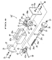
- an X-axis fine displacement mechanism 80 of the micromanipulator 3 includes an X-axis outer slider 63 as a fine displacement member provided with a pair of inner guiding grooves 63a.
- An X-axis inner slider 65 is slidably mounted within the outer slider 63 through a non-shown linear-way bearing. The X-axis inner slider 65 is stationarily retained, while the X-axis outer slider 63 is slidable with respect to the X-axis inner slider 65.
- Such restriction occurs also to the actuating-side of the micromanipulator apparatus. Since the oil chambers 76', 75' are provided on the common X-axis outer slider 63 in opposing relation to each other, the volume change in one oil chamber is restricted by the hydraulic fluid in the other oil chamber. With such arrangement of the two hydraulic closed circuits, a volume change of hydraulic fluid is restricted, thereby drift of the microtool 9 fixed to the X-axis outer slider 63 can be prevented.
- the first hydraulic closed circuit functions as part of the micromanipulator fine control unit and the hydraulically-operated micromanipulator, while the second hydraulic closed circuit functions as restricting means.
Landscapes
- Engineering & Computer Science (AREA)
- Chemical & Material Sciences (AREA)
- Life Sciences & Earth Sciences (AREA)
- Health & Medical Sciences (AREA)
- Zoology (AREA)
- Genetics & Genomics (AREA)
- Organic Chemistry (AREA)
- Wood Science & Technology (AREA)
- Bioinformatics & Cheminformatics (AREA)
- Physics & Mathematics (AREA)
- Biotechnology (AREA)
- Microbiology (AREA)
- Analytical Chemistry (AREA)
- General Physics & Mathematics (AREA)
- Biomedical Technology (AREA)
- Optics & Photonics (AREA)
- Sustainable Development (AREA)
- Mechanical Engineering (AREA)
- Cell Biology (AREA)
- Biochemistry (AREA)
- General Engineering & Computer Science (AREA)
- General Health & Medical Sciences (AREA)
- Robotics (AREA)
- Manipulator (AREA)
- Microscoopes, Condenser (AREA)
- Supply Devices, Intensifiers, Converters, And Telemotors (AREA)
Claims (6)
- Hydraulisch betätigte Mikromanipulationsvorrichtung (1), umfassend einen ersten betätigungsseitigen Kolben (37) und einen ersten betätigungsseitigen Hydraulikzylinder (41), die zueinander in einer Arbeitsbeziehung stehen und in Bezug aufeinander als Reaktion auf eine Bewegung einer Feinsteuerungsvorrichtung (50, 50') feinbewegbar sind, wobei einer aus dem ersten betätigungsseitigen Hydraulikzylinder und dem ersten betätigungsseitigen Kolben feststehend gehalten ist,
einen ersten antriebsseitigen Kolben (72) und einen ersten antriebsseitigen Hydraulikzylinder (76), die zueinander in einer Arbeitsbeziehung stehen und in Bezug aufeinander feinbewegbar sind, wobei der erste antriebsseitige Hydraulikzylinder (76) über einen Schlauch (47) mit dem ersten betätigungsseitigen Hydraulikzylinder (41) verbunden ist, um einen ersten geschlossenen Hydraulikkreis zu bilden, und wobei einer aus dem ersten antriebsseitigen Kolben (72) und dem ersten antriebsseitigen Hydraulikzylinder (76) feststehend gehalten ist, wobei der nicht festgehaltene antriebsseitige Kolben oder Zylinder an einem Feinverschiebungselement (63) angebracht ist und wobei der erste geschlossene Hydraulikkreis mit einem Hydraulikfluid gefüllt ist,
und ein Kompensationsmittel, um bei einer Änderung der Umgebungstemperatur eine Ausdehnung und Kontraktion des Hydraulikfluids im Inneren des ersten geschlossenen Hydraulikkreis zu verhindern,
dadurch gekennzeichnet, dass das Kompensationsmittel einen weiteren, zweiten geschlossenen Hydraulikkreis bildet, der dem ersten geschlossenen Hydraulikkreis ähnlich ist, und folgendes umfasst:einen zweiten betätigungsseitigen Kolben (38, 38') und einen zweiten betätigungsseitigen Hydraulikzylinder (42), wobei einer aus dem zweiten betätigungsseitigen Kolben (38, 38') und dem zweiten betätigungsseitigen Hydraulikzylinder (42) feststehend gehalten ist, und wobei der erste nicht festgehaltene, betätigungsseitige Kolben oder Zylinder in gegenüberliegender Beziehung zum zweiten nicht festgehaltenen, betätigungsseitigen Kolben oder Zylinder steht,einen zweiten antriebsseitigen Kolben (71) und einen zweiten antriebsseitigen Hydraulikzylinder (75), wobei einer aus dem zweiten antriebsseitigen Kolben (71) und dem zweiten antriebsseitigen Hydraulikzylinder (75) feststehend gehalten ist, wobei der zweite nicht festgehaltene, antriebsseitige Kolben oder Zylinder an dem Feinverschiebungselement (63) angebracht ist, und wobei der erste nicht festgehaltene, antriebsseitige Kolben oder Zylinder in gegenüberliegender Beziehung zum zweiten, nicht festgehaltenen antriebsseitigen Kolben oder Zylinder steht,und einen Schlauch (48), der den zweiten antriebsseitigen Hydraulikzylinder (75) mit dem zweiten betätigungsseitigen Hydraulikzylinder (42) verbindet, wobei der zweite geschlossene Hydraulikkreis mit einem Hydraulikfluid gefüllt ist,weiters gekennzeichnet dadurch, dass der zweite geschlossene Hydraulikkreis mit dem ersten geschlossenen Hydraulikkreis zusammenwirkt, wobei die Anordnung solcherart ist, dass beim Betrieb jeder nicht festgehaltene betätigungsseitige Kolben oder Zylinder durch die Feinsteuerungsvorrichtung (50, 50') verschoben wird, um das Volumen des Hydraulikfluids im Inneren des entsprechenden betätigungsseitigen Hydraulikzylinders (41, 42) zu ändern, und jeder nicht festgehaltene antriebsseitige Kolben oder Zylinder in Bezug auf den feststehend gehaltenen antriebsseitigen Hydraulikzylinder oder Kolben, zu dem er in einer Arbeitsbeziehung steht, verschoben wird, wenn die Änderungen des Volumens der betätigungsseitigen Hydraulikzylinder (41, 42) durch die Schläuche (47, 48) an die antriebsseitigen Hydraulikzylinder (76, 75) übertragen werden. - Hydraulisch betätigte Mikromanipulationsvorrichtung nach Anspruch 1, worin das Volumen des Hydraulikfluids zwischen dem ersten betätigungsseitigen Hydraulikzylinder (41) und dem ersten antriebsseitigen Hydraulikzylinder (76) im Wesentlichen jenem des Hydraulikfluids zwischen dem zweiten betätigungsseitigen Hydraulikzylinder (42) und dem zweiten antriebsseitigen Hydraulikzylinder (75) entspricht.
- Hydraulisch betätigte Mikromanipulationsvorrichtung nach Anspruch 1 oder 2, worin der erste betätigungsseitige Kolben (37) und der zweite betätigungsseitige Hydraulikzylinder (42) feststehend gehalten sind, während der erste betätigungsseitige Hydraulikzylinder (41) und der zweite betätigungsseitige Kolben (38, 38') beweglich sind, und worin der nicht festgehaltene betätigungsseitige Hydraulikzylinder und der nicht festgehaltene betätigungsseitige Kolben durch die Feinsteuerungsvorrichtung (50, 50') in feinbetätigbar sind.
- Hydraulisch betätigte Mikromanipulationsvorrichtung nach einem der Ansprüche 1 bis 3, worin der erste antriebsseitige Kolben (72) und der zweite antriebsseitige Hydraulikzylinder (75) feststehend gehalten sind, während der erste antriebsseitige Hydraulikzylinder (76) und der zweite antriebsseitige Kolben (71) beweglich sind, und worin der nicht festgehaltene antriebsseitige Hydraulikzylinder und der nicht festgehaltene antriebsseitige Kolben am Feinverschiebungselement (63) angebracht sind.
- Hydraulisch betätigte Mikromanipulationsvorrichtung nach einem der Ansprüche 1 bis 4, worin das Volumen des Hydraulikfluids im Inneren des ersten betätigungsseitigen Hydraulikzylinders (41) reduziert wird, wenn das Volumen des Hydraulikfluids im Inneren des zweiten betätigungsseitigen Hydraulikzylinders (42) zunimmt, und das Volumen des Hydraulikfluids im Inneren des ersten betätigungsseitigen Hydraulikzylinders (41) zunimmt, wenn das Volumen des Hydraulikfluids im Inneren des zweiten betätigungsseitigen Hydraulikzylinders (42) reduziert wird.
- Hydraulisch betätigte Mikromanipulationsvorrichtung nach einem der Ansprüche 1 bis 5, worin die Mikromanipulationsvorrichtung eine Feinverschiebung in drei Richtungen ermöglicht.
Priority Applications (1)
| Application Number | Priority Date | Filing Date | Title |
|---|---|---|---|
| EP01118683A EP1163983A3 (de) | 1997-09-03 | 1998-09-03 | Hydraulisch gesteuerter Mikromanipulator |
Applications Claiming Priority (12)
| Application Number | Priority Date | Filing Date | Title |
|---|---|---|---|
| JP23815897 | 1997-09-03 | ||
| JP238158/97 | 1997-09-03 | ||
| JP23815897 | 1997-09-03 | ||
| JP34116197 | 1997-12-11 | ||
| JP34116197A JPH11138469A (ja) | 1997-09-03 | 1997-12-11 | 液圧遠隔操作型マイクロマニピュレータ装置 |
| JP341161/97 | 1997-12-11 | ||
| JP16223598A JP3316675B2 (ja) | 1998-06-10 | 1998-06-10 | 液圧遠隔操作型マイクロマニピュレータ装置 |
| JP16223598 | 1998-06-10 | ||
| JP162236/98 | 1998-06-10 | ||
| JP162235/98 | 1998-06-10 | ||
| JP16223698 | 1998-06-10 | ||
| JP16223698A JP3341151B2 (ja) | 1998-06-10 | 1998-06-10 | 液圧遠隔操作型マイクロマニピュレータ装置 |
Related Child Applications (1)
| Application Number | Title | Priority Date | Filing Date |
|---|---|---|---|
| EP01118683A Division EP1163983A3 (de) | 1997-09-03 | 1998-09-03 | Hydraulisch gesteuerter Mikromanipulator |
Publications (3)
| Publication Number | Publication Date |
|---|---|
| EP0906813A2 EP0906813A2 (de) | 1999-04-07 |
| EP0906813A3 EP0906813A3 (de) | 2000-01-05 |
| EP0906813B1 true EP0906813B1 (de) | 2005-11-30 |
Family
ID=27473789
Family Applications (2)
| Application Number | Title | Priority Date | Filing Date |
|---|---|---|---|
| EP98307077A Expired - Lifetime EP0906813B1 (de) | 1997-09-03 | 1998-09-03 | Hydraulisch gesteuerter Mikromanipulator |
| EP01118683A Withdrawn EP1163983A3 (de) | 1997-09-03 | 1998-09-03 | Hydraulisch gesteuerter Mikromanipulator |
Family Applications After (1)
| Application Number | Title | Priority Date | Filing Date |
|---|---|---|---|
| EP01118683A Withdrawn EP1163983A3 (de) | 1997-09-03 | 1998-09-03 | Hydraulisch gesteuerter Mikromanipulator |
Country Status (3)
| Country | Link |
|---|---|
| US (2) | US6050153A (de) |
| EP (2) | EP0906813B1 (de) |
| DE (1) | DE69832568T2 (de) |
Families Citing this family (17)
| Publication number | Priority date | Publication date | Assignee | Title |
|---|---|---|---|---|
| US8256430B2 (en) | 2001-06-15 | 2012-09-04 | Monteris Medical, Inc. | Hyperthermia treatment and probe therefor |
| WO2002007608A2 (en) * | 2000-07-20 | 2002-01-31 | Tiva Medical, Inc. | Hand-actuated articulating surgical tool |
| US20040003679A1 (en) * | 2002-07-05 | 2004-01-08 | David Ide | Apparatus and method for in vitro recording and stimulation of cells |
| KR20080025366A (ko) * | 2005-04-29 | 2008-03-20 | 텐딕스 디벨롭먼트, 엘엘씨 | 래디얼 임펄스 엔진, 펌프 및 압축기 시스템과 관련 동작방법 |
| BRPI0719934A2 (pt) * | 2006-12-05 | 2014-03-11 | Allegiance Corp | Dispositivo para uso em posicionamento de um instrumento para uso em procedimento cirúrgico e método para posicionar, relativamente a um paciente, um instrumento para uso em um procedimento cirúrgico |
| JP4926929B2 (ja) * | 2007-12-10 | 2012-05-09 | オリンパス株式会社 | チップ駆動装置 |
| US8728092B2 (en) | 2008-08-14 | 2014-05-20 | Monteris Medical Corporation | Stereotactic drive system |
| US20100242891A1 (en) * | 2008-10-30 | 2010-09-30 | Timber Dick | Radial impulse engine, pump, and compressor systems, and associated methods of operation |
| US8979871B2 (en) | 2009-08-13 | 2015-03-17 | Monteris Medical Corporation | Image-guided therapy of a tissue |
| EP2378342A1 (de) * | 2010-04-15 | 2011-10-19 | Mmi Ag | Mikromanipulationssystem mit Schutzvorrichtung für Kapillaren |
| JP5570318B2 (ja) * | 2010-06-23 | 2014-08-13 | Obara Group株式会社 | 溶接機のイコライズ装置 |
| US9700342B2 (en) | 2014-03-18 | 2017-07-11 | Monteris Medical Corporation | Image-guided therapy of a tissue |
| US10675113B2 (en) | 2014-03-18 | 2020-06-09 | Monteris Medical Corporation | Automated therapy of a three-dimensional tissue region |
| US9492121B2 (en) | 2014-03-18 | 2016-11-15 | Monteris Medical Corporation | Image-guided therapy of a tissue |
| US10327830B2 (en) | 2015-04-01 | 2019-06-25 | Monteris Medical Corporation | Cryotherapy, thermal therapy, temperature modulation therapy, and probe apparatus therefor |
| RU2723759C1 (ru) * | 2019-12-19 | 2020-06-17 | Лев Николаевич Гоголев | Конструкция микроманипулятора для позиционирования инструментария |
| WO2022006388A1 (en) * | 2020-07-01 | 2022-01-06 | University Of Florida Research Foundation | In-situ servo-hydraulic bio-manipulator |
Family Cites Families (7)
| Publication number | Priority date | Publication date | Assignee | Title |
|---|---|---|---|---|
| JPS61265283A (ja) * | 1985-05-17 | 1986-11-25 | 株式会社 成茂科学器械研究所 | 硝子電極等のマニピユレ−タ |
| US4946329A (en) * | 1988-04-01 | 1990-08-07 | Albert Einstein College Of Medicine Of Yeshiva University | Micromanipulator using hydraulic bellows |
| US5287700A (en) * | 1992-10-14 | 1994-02-22 | Mcdonnell Douglas Helicopter Company | Flexible bellows actuation system |
| JP3362879B2 (ja) * | 1992-11-10 | 2003-01-07 | オリンパス光学工業株式会社 | マイクロマニピュレータ |
| JP3368490B2 (ja) * | 1996-06-25 | 2003-01-20 | 株式会社ナリシゲ | マイクロマニピュレータ微動操作装置 |
| US5943914A (en) * | 1997-03-27 | 1999-08-31 | Sandia Corporation | Master-slave micromanipulator apparatus |
| DE19754883C2 (de) * | 1997-12-10 | 2002-02-07 | Hyco Pacoma Gmbh | Hydraulische Gleichlaufschaltung mit mindestens einem Hauptzylinder und mindestens einem Folgezylinder |
-
1998
- 1998-09-03 US US09/146,551 patent/US6050153A/en not_active Expired - Lifetime
- 1998-09-03 DE DE69832568T patent/DE69832568T2/de not_active Expired - Lifetime
- 1998-09-03 EP EP98307077A patent/EP0906813B1/de not_active Expired - Lifetime
- 1998-09-03 EP EP01118683A patent/EP1163983A3/de not_active Withdrawn
-
1999
- 1999-12-06 US US09/455,500 patent/US6131480A/en not_active Expired - Lifetime
Also Published As
| Publication number | Publication date |
|---|---|
| DE69832568D1 (de) | 2006-01-05 |
| US6050153A (en) | 2000-04-18 |
| EP1163983A3 (de) | 2003-05-02 |
| EP1163983A2 (de) | 2001-12-19 |
| EP0906813A3 (de) | 2000-01-05 |
| DE69832568T2 (de) | 2006-07-27 |
| US6131480A (en) | 2000-10-17 |
| EP0906813A2 (de) | 1999-04-07 |
Similar Documents
| Publication | Publication Date | Title |
|---|---|---|
| EP0906813B1 (de) | Hydraulisch gesteuerter Mikromanipulator | |
| JP3900664B2 (ja) | 顕微鏡 | |
| US20030021017A1 (en) | Arrangement for micromanipulation of biological specimens | |
| DE3511165A1 (de) | Probenheizeinrichtung fuer mikroskope | |
| WO2008131840A2 (de) | Probenhalterung für ein mikroskop | |
| GB2186706A (en) | Micromanipulator | |
| US20050057799A1 (en) | Microscope | |
| EP0816023B1 (de) | Feineinstellungseinrichtung für Mikromanipulator | |
| US5771749A (en) | Slide mechanism combined rough and fine adjustment in micromanipulator | |
| US7233438B2 (en) | Specimen temperature adjusting apparatus | |
| EP4664181A2 (de) | Inverses mikroskop | |
| EP0816022B1 (de) | Feineinstellungseinrichtung für Mikromanipulator | |
| EP0816021B1 (de) | Feineinstellungseinrichtung für Mikromanipulator | |
| US7408704B2 (en) | Device for optically controlled micro-manipulation of biological specimens | |
| JPH11138469A (ja) | 液圧遠隔操作型マイクロマニピュレータ装置 | |
| JP3295836B2 (ja) | 液圧遠隔操作型マイクロマニピュレータ装置 | |
| JP3326588B2 (ja) | マイクロマニピュレータ微動操作装置 | |
| JP3341151B2 (ja) | 液圧遠隔操作型マイクロマニピュレータ装置 | |
| Kasten | Hydraulically Operated Microscope Stage | |
| JPS6047569B2 (ja) | マイクロマニピユレ−タ | |
| JPS6326924Y2 (de) | ||
| US20020005983A1 (en) | Microscope stepping device | |
| SU1756140A1 (ru) | Микроманипул тор | |
| JP3316675B2 (ja) | 液圧遠隔操作型マイクロマニピュレータ装置 | |
| WO2007073521A2 (en) | Microscope control device |
Legal Events
| Date | Code | Title | Description |
|---|---|---|---|
| PUAI | Public reference made under article 153(3) epc to a published international application that has entered the european phase |
Free format text: ORIGINAL CODE: 0009012 |
|
| AK | Designated contracting states |
Kind code of ref document: A2 Designated state(s): DE FR GB |
|
| AX | Request for extension of the european patent |
Free format text: AL;LT;LV;MK;RO;SI |
|
| PUAL | Search report despatched |
Free format text: ORIGINAL CODE: 0009013 |
|
| AK | Designated contracting states |
Kind code of ref document: A3 Designated state(s): AT BE CH CY DE DK ES FI FR GB GR IE IT LI LU MC NL PT SE |
|
| AX | Request for extension of the european patent |
Free format text: AL;LT;LV;MK;RO;SI |
|
| 17P | Request for examination filed |
Effective date: 20000614 |
|
| AKX | Designation fees paid |
Free format text: DE FR GB |
|
| 17Q | First examination report despatched |
Effective date: 20010424 |
|
| GRAP | Despatch of communication of intention to grant a patent |
Free format text: ORIGINAL CODE: EPIDOSNIGR1 |
|
| GRAS | Grant fee paid |
Free format text: ORIGINAL CODE: EPIDOSNIGR3 |
|
| GRAA | (expected) grant |
Free format text: ORIGINAL CODE: 0009210 |
|
| AK | Designated contracting states |
Kind code of ref document: B1 Designated state(s): DE FR GB |
|
| REG | Reference to a national code |
Ref country code: GB Ref legal event code: FG4D |
|
| REF | Corresponds to: |
Ref document number: 69832568 Country of ref document: DE Date of ref document: 20060105 Kind code of ref document: P |
|
| ET | Fr: translation filed | ||
| PLBE | No opposition filed within time limit |
Free format text: ORIGINAL CODE: 0009261 |
|
| STAA | Information on the status of an ep patent application or granted ep patent |
Free format text: STATUS: NO OPPOSITION FILED WITHIN TIME LIMIT |
|
| 26N | No opposition filed |
Effective date: 20060831 |
|
| REG | Reference to a national code |
Ref country code: FR Ref legal event code: PLFP Year of fee payment: 19 |
|
| REG | Reference to a national code |
Ref country code: FR Ref legal event code: PLFP Year of fee payment: 20 |
|
| PGFP | Annual fee paid to national office [announced via postgrant information from national office to epo] |
Ref country code: DE Payment date: 20170825 Year of fee payment: 20 Ref country code: GB Payment date: 20170818 Year of fee payment: 20 Ref country code: FR Payment date: 20170825 Year of fee payment: 20 |
|
| REG | Reference to a national code |
Ref country code: DE Ref legal event code: R071 Ref document number: 69832568 Country of ref document: DE |
|
| REG | Reference to a national code |
Ref country code: GB Ref legal event code: PE20 Expiry date: 20180902 |
|
| PG25 | Lapsed in a contracting state [announced via postgrant information from national office to epo] |
Ref country code: GB Free format text: LAPSE BECAUSE OF EXPIRATION OF PROTECTION Effective date: 20180902 |