EP0906813B1 - Hydraulically-operated micromanipulator apparatus - Google Patents
Hydraulically-operated micromanipulator apparatus Download PDFInfo
- Publication number
- EP0906813B1 EP0906813B1 EP98307077A EP98307077A EP0906813B1 EP 0906813 B1 EP0906813 B1 EP 0906813B1 EP 98307077 A EP98307077 A EP 98307077A EP 98307077 A EP98307077 A EP 98307077A EP 0906813 B1 EP0906813 B1 EP 0906813B1
- Authority
- EP
- European Patent Office
- Prior art keywords
- operating
- hydraulic cylinder
- actuating
- retained
- piston
- Prior art date
- Legal status (The legal status is an assumption and is not a legal conclusion. Google has not performed a legal analysis and makes no representation as to the accuracy of the status listed.)
- Expired - Lifetime
Links
Images


Classifications
-
- G—PHYSICS
- G02—OPTICS
- G02B—OPTICAL ELEMENTS, SYSTEMS OR APPARATUS
- G02B21/00—Microscopes
- G02B21/32—Micromanipulators structurally combined with microscopes
-
- B—PERFORMING OPERATIONS; TRANSPORTING
- B25—HAND TOOLS; PORTABLE POWER-DRIVEN TOOLS; MANIPULATORS
- B25J—MANIPULATORS; CHAMBERS PROVIDED WITH MANIPULATION DEVICES
- B25J7/00—Micromanipulators
-
- C—CHEMISTRY; METALLURGY
- C12—BIOCHEMISTRY; BEER; SPIRITS; WINE; VINEGAR; MICROBIOLOGY; ENZYMOLOGY; MUTATION OR GENETIC ENGINEERING
- C12M—APPARATUS FOR ENZYMOLOGY OR MICROBIOLOGY; APPARATUS FOR CULTURING MICROORGANISMS FOR PRODUCING BIOMASS, FOR GROWING CELLS OR FOR OBTAINING FERMENTATION OR METABOLIC PRODUCTS, i.e. BIOREACTORS OR FERMENTERS
- C12M35/00—Means for application of stress for stimulating the growth of microorganisms or the generation of fermentation or metabolic products; Means for electroporation or cell fusion
-
- Y—GENERAL TAGGING OF NEW TECHNOLOGICAL DEVELOPMENTS; GENERAL TAGGING OF CROSS-SECTIONAL TECHNOLOGIES SPANNING OVER SEVERAL SECTIONS OF THE IPC; TECHNICAL SUBJECTS COVERED BY FORMER USPC CROSS-REFERENCE ART COLLECTIONS [XRACs] AND DIGESTS
- Y10—TECHNICAL SUBJECTS COVERED BY FORMER USPC
- Y10T—TECHNICAL SUBJECTS COVERED BY FORMER US CLASSIFICATION
- Y10T74/00—Machine element or mechanism
- Y10T74/20—Control lever and linkage systems
- Y10T74/20207—Multiple controlling elements for single controlled element
- Y10T74/20372—Manual controlling elements
- Y10T74/20378—Planar surface with orthogonal movement or rotation
Definitions
- the micromanipulator 305 is attached with various kinds of microtools 308, such as a glass electrode for the corresponding cell treatments and includes a three dimensional displacement mechanism for moving the tip end of the microtool 308 in three dimensions.
- the three dimensional displacement mechanism is finely operated by hydraulic pressure through a joystick 309.
- an X-axis fine displacement mechanism 80 of the micromanipulator 3 includes an X-axis outer slider 63 as a fine displacement member provided with a pair of inner guiding grooves 63a.
- An X-axis inner slider 65 is slidably mounted within the outer slider 63 through a non-shown linear-way bearing. The X-axis inner slider 65 is stationarily retained, while the X-axis outer slider 63 is slidable with respect to the X-axis inner slider 65.
- Such restriction occurs also to the actuating-side of the micromanipulator apparatus. Since the oil chambers 76', 75' are provided on the common X-axis outer slider 63 in opposing relation to each other, the volume change in one oil chamber is restricted by the hydraulic fluid in the other oil chamber. With such arrangement of the two hydraulic closed circuits, a volume change of hydraulic fluid is restricted, thereby drift of the microtool 9 fixed to the X-axis outer slider 63 can be prevented.
- the first hydraulic closed circuit functions as part of the micromanipulator fine control unit and the hydraulically-operated micromanipulator, while the second hydraulic closed circuit functions as restricting means.
Landscapes
- Engineering & Computer Science (AREA)
- Chemical & Material Sciences (AREA)
- Life Sciences & Earth Sciences (AREA)
- Health & Medical Sciences (AREA)
- Zoology (AREA)
- Genetics & Genomics (AREA)
- Organic Chemistry (AREA)
- Wood Science & Technology (AREA)
- Bioinformatics & Cheminformatics (AREA)
- Physics & Mathematics (AREA)
- Biotechnology (AREA)
- Microbiology (AREA)
- Analytical Chemistry (AREA)
- General Physics & Mathematics (AREA)
- Biomedical Technology (AREA)
- Optics & Photonics (AREA)
- Sustainable Development (AREA)
- Mechanical Engineering (AREA)
- Cell Biology (AREA)
- Biochemistry (AREA)
- General Engineering & Computer Science (AREA)
- General Health & Medical Sciences (AREA)
- Robotics (AREA)
- Manipulator (AREA)
- Microscoopes, Condenser (AREA)
- Supply Devices, Intensifiers, Converters, And Telemotors (AREA)
Description
- The present invention relates to hydraulically-operated micromanipulator apparatus including microtools, such as a glass electrode positioned in the field of a microscope with the use of hydraulically-operated remote controlling means.
- In basic medical science or biotechnology, micromanipulators are used for treating cells, such as creature's organs, cellular textures, egg cells and the like. These cells are treated in various operations for example suctioning, injecting and dividing by finely controlling a microtool in the field of a microscope.
- However, when an operator finely controls the micromanipulator by his direct contact with its control handle, his hand trembling may be multiplied and transmitted to the microtool through the body frame. For this reason, care should be taken for finely controlling the micromanipulator. Since the micromanipulator needs to be gently operated without hand trembling, delicate operations, the greatest possible care and a lot of skills are required. In view of these difficulties, a various hydraulically-operated micromanipulators have been proposed for finely controlling the microtool by remote controlling means. These micromanipulators are controlled by hydraulic fluid, such as hydraulic oil.
- Referring now to Fig.1, a conventional cell treatment device comprising a
stage 303 for mounting aPetri dish 302 containing thereinegg cells 301 dipped in a reagent, a fixedretaining unit 304 for stationary retaining thecells 301, amicromanipulator 305 for carrying out a practical cell treatment, and anoptical system 306 for observing images of thecells 301 irradiated with light. The cell treatment device is operated on a vibration-proof mat 307. - The
micromanipulator 305 is attached with various kinds ofmicrotools 308, such as a glass electrode for the corresponding cell treatments and includes a three dimensional displacement mechanism for moving the tip end of themicrotool 308 in three dimensions. The three dimensional displacement mechanism is finely operated by hydraulic pressure through ajoystick 309. - The
joystick 309 comprises acontrol handle 311 downwardly extending from the distal end of a visor-shaped supportingframe 310 and a transmittingunit 313 for transmitting the twodirectional movement 312 of thecontrol handle 311 shown by the arrows through hydraulic pressure. Thecontrol handle 311 is provided with a convertingunit 314 for converting the two directional movement of thecontrol handle 311 into a mechanical displacement in a horizontal plane. The convertingunit 314 connects the supportingframe 310 and thecontrol handle 311. For the vertical movement of the cells to be treated, another mechanism may be provided at an adjacent position of thejoystick 309. - In other conventional device, the control handle extends upwardly from the converting
unit 314. However, since the operator can operate the device at a lower position without raising his arm, the former type, i.e., the micromanipulator with downwardly extending control handle has been widely used. - However, in micromanipulators operable by hydraulic pressure, such as oil pressure or water pressure, when ambient temperature changes, the volume of hydraulic fluid may also change. This leads to drift of the tip end of the microtool, and hence accurate observation or operation is not achieved.
- Other electrically-operable micromanipulator is also known. However, in such micromanipulator, the tip end of the microtool drifts when it is subject to electric hindrance. The problem relates to drift, therefore, remain unsolved.
- Such problems are serious when a long period of observation or operation is carried out while the tip end of the microtool is abutting to a sample. When drift occurs, the tip end of the microtool moves off from the sample, and hence the observation or operation is interrupted.
- US 4679976 discloses a conventional micromanipulator apparatus having a single hydraulic closed circuit for X, Y and Z-axis displacement respectively, such apparatus suffering from a drift of the microtool when the ambient temperature changes.
- US 4946329 discloses a mechanism for compensating for thermal expansion and contraction of fluid in the hydraulic control system of a micromanipulator, the compensating mechanism being connected to a micromanipulator of the single closed hydraulic circuit type such as disclosed in US 4679976.
- With the foregoing drawbacks in view, the present invention seeks to provide micromanipulator apparatus, which are hydraulically-operable by remote controlling means and include means for compensating drift of the microtool due to a temperature change.
- According to the present invention, there is provided a hydraulically-operated micromanipulator apparatus, which comprises a first operating-side piston and a first operating-side hydraulic cylinder operatively related to each other and finely movable relative to one another in response to movement of a fine control device, one of the first operating-side hydraulic cylinder and the first operating-side piston being stationarily retained, a first actuating-side piston and a first actuating-side hydraulic cylinder operatively related to each other and finely movable relative to one another, the first actuating-side hydraulic cylinder being connected to the first operating-side hydraulic cylinder through a hose so as to form a first closed hydraulic circuit, one of the first actuating-side piston and the first actuating-side hydraulic cylinder being stationarily retained, the non-retained actuating-side piston or cylinder being attached to a fine displacement member, the first closed hydraulic circuit being filled with hydraulic fluid, and a compensating means for preventing expansion and contraction of hydraulic fluid within the first closed hydraulic circuit when the ambient temperature changes, characterised in that said compensating means forms another second closed hydraulic circuit similar to the first closed hydraulic circuit and includes a second operating-side piston and a second operating-side hydraulic cylinder, one of the second operating-side piston and the second operating-side hydraulic cylinder being stationarily retained, the first non-retained operating side piston or cylinder being in opposing relation to the second non-retained operating side piston or cylinder, a second actuating-side piston and a second actuating-side hydraulic cylinder, one of the second actuating-side piston and the second actuating-side hydraulic cylinder being stationarily retained, the second non-retained actuating-side piston or cylinder being attached to the fine displacement member (63), and the first non-retained actuating-side piston or cylinder being in opposing relation to the second non-retained actuating side piston or cylinder, a hose connecting the second actuating-side hydraulic cylinder and the second operating-side hydraulic cylinder, the second closed hydraulic circuit being filled with hydraulic fluid, and further characterised in that said second closed hydraulic circuit cooperates with said first closed hydraulic circuit, the arrangement being such that, in operation, each non-retained operating-side piston or cylinder is displaced by said fine control device for changing the volume of hydraulic fluid within the respective operating-side hydraulic cylinder, and each non-retained actuating-side piston or cylinder is displaced with respect to its operatively related stationarily retained actuating-side hydraulic cylinder or piston wwhen the volume changes of said operating-side hydraulic cylinders are transmitted through the hoses to said actuating-side hydraulic cylinders.
- Preferably the volume of hydraulic fluid between said first operating-side hydraulic cylinder and said first actuating-side hydraulic cylinder is substantially the same as that of hydraulic fluid between said second operating-side hydraulic cylinder and said second actuating-side hydraulic cylinder.
- Said first operating-side piston and said second operating-side hydraulic cylinder may be stationarily retained, while said first operating-side hydraulic cylinder and said second operating-side piston may be movable, and wherein the non-retained operating-side hydraulic cylinder and the non-retained operating-side piston may be finely operable by said fine control device.
- Said first actuating-side piston and said second actuating-side hydraulic cylinder may be stationarily retained, while said first actuating-side hydraulic cylinder and said second actuating-side piston may be movable, and wherein the non-retained actuating-side hydraulic cylinder and the non-retained actuating-side piston may be attached to said fine displacement member.
- Preferably the volume of hydraulic fluid within said first operating-side hydraulic cylinder is reduced when the volume of hydraulic fluid within said second operating-side hydraulic cylinder is increased, and the volume of the hydraulic fluid within said first operating side hydraulic cylinder is increased when the volume of the hydraulic fluid within said second operating-side hydraulic cylinder is reduced.
- The micromanipulator fine control unit may provide three-directional fine displacement of the hydraulically-operated micromanipulator.
-
- Fig. 1 is an explanatory view schematically showing a conventional cell treatment device.
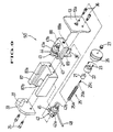
- Fig. 2 is a perspective view showing a first embodiment of a hydraulically-operated micromanipulator apparatus according to the present invention.
- Fig. 3 is a perspective view showing an X-axis fine control mechanism of a micromanipulator fine control unit according to the first embodiment of the invention.
- Fig. 4 is an exploded perspective view showing the X-axis fine control mechanism of Fig. 3.
- Fig. 5 is a perspective view showing an X-axis fine displacement mechanism of a micromanipulator according to first embodiment of the invention.
- Fig. 6 is an exploded perspective view showing the X-axis fine displacement mechanism of Fig. 5.
- Fig. 7 is a sectional view taken along the line I-I of Fig. 5.
- Fig. 8 is a table for the result of a comparative test, in which the relation between temperature change and amount of drift is shown for the inventive and a conventional hydraulically-operated micromanipulator apparatus.
- Fig. 9 is an exploded perspective view showing a modified embodiment of the X-axis fine control mechanism.
-
- The present invention will be described with reference to three preferred embodiments. Although the term "hydraulically-operated micromanipulator apparatus" is herein used as an apparatus operable by oil pressure, it also includes an apparatus operable by water pressure of other fluid pressure.
- Referring now to Fig. 2, a first embodiment of a hydraulically-operated micromanipulator apparatus according to the present invention is shown, in which the
micromanipulator apparatus 1 comprises a micromanipulatorfine control unit 2 having handles for three-directional control and a hydraulically-operatedmicromanipulator 3. The micromanipulatorfine control unit 2 is connected to the hydraulically-operated micromanipulator 3 (hereinafter referred to as a micromanipulator) through a plurality ofhoses micromanipulator 3 is fixed to amounting bar 6 which is supported to apole 5. A tighteningdevice 7 is mounted on themicromanipulator 3 for supporting aholder 8. Amicrotool 9 is attached to the front end of theholder 8. - A micromanipulator
fine control unit 2 has abase plate 11 to which is mounted fourside plates top plate 17. Thebase plate 11, the fourside plates top plate 17 are fixed to each other, thereby providing acase 18. - The micromanipulator
fine control unit 2 includes an X-axisfine control mechanism 50 for finely displacing themicrotool 9 to the X-axis directions, i.e. right-and-left directions. As shown in Figs.3 and 4, theside plate 13 is centrally provided with a through opening 13a through which the front portion of a bearingmetal 21 is fitted. The bearingmetal 21 is fitted within aring 22, which is fixed to theside plate 13 by a plurality ofbolts 23. The bearingmetal 21 has a central through-opening for receiving an X-axis finecontrol screw shaft 25. The X-axis finecontrol screw shaft 25 comprises a finecontrol male thread 25a, astem portion 25b having reduced diameter and received in the central through-opening of thebearing metal 21, and a fixingmale thread 25c provided at one end of thestem portion 25b remote from the finecontrol male thread 25a. - An X-axis
fine control handle 26 is rotatably fitted over thering 22. The X-axisfine control handle 26 has a cylindrical shape, one end of which is open for receiving therein thering 22. The closed end of the X-axisfine control handle 26 forms a knurled head. The fixingmale thread 25c threadly engages with a central threaded through-opening of the control handle 26 and further with a fixingnut 27. The X-axis fine control handle 26 is thus fixed to the X-axis finecontrol screw shaft 25. - An
outer slider 30 as a basement has a pair of guidinggrooves 30a for receiving aninner slider 31 as a sliding table through a non-shown linear-way bearing. Theinner slider 31 is provided at the tailing end with a threadedopening 31a for the engagement with the fine controlmale thread 25a of the X-axis finecontrol screw shaft 25. At one end of theouter slider 30, aside plate member 33 is fixed by a plurality ofbolts 35, while the other end is mounted to theside plate 13 of thecase 18 by a plurality ofbolts 36. Afirst piston 37 is extending from the inner end of theside plate member 33, and asecond piston 38 is extending from the inner end of theside plate 13. - Mounted centrally on the top surface of the inner slider is a
central plate 40 so as to separate the top surface into two halves. A firsthydraulic cylinder 41 and a secondhydraulic cylinder 42 are mounted on the respective halves bycylinder fixing elements respective pistons hydraulic cylinder collar cylinder fixing element hose coupling hose hose 47 as a first hose connects the firsthydraulic cylinder 41 and an X-axishydraulic cylinder 76 hereinafter described. Thehose 48 as a second hose connects the secondhydraulic cylinder 42 and an X-axishydraulic cylinder 75 hereinafter described. - The
piston 37 is inserted within thehydraulic cylinder 41 so as to provide an oil chamber 41', and thepiston 38 is inserted within thehydraulic cylinder 42 so as to provide an oil chamber 42'. - The X-axis
fine control mechanism 50 comprises the X-axis fine control handle 26, the X-axis finecontrol screw shaft 25, the bearingmetal 21, thering 22, theouter slider 30, theinner slider 31, thehydraulic cylinders pistons - In the X-axis
fine control mechanism 50, the X-axis finecontrol screw shaft 25 is rotated when an operator moves the X-axis fine control handle 26. Since the fine controlmale thread 25a of the X-axis finecontrol screw shaft 25 is fixed to theinner slider 31, the volumes of the oil chambers 41', 42' are changed by the displacement of theinner slider 31 when the X-axis fine control handle 26 is rotated. - As shown in Fig.2, the micromanipulator
fine control unit 2 also includes a Y-axisfine control mechanism 51 for fore-and-aft movement and a Z-axisfine control mechanism 52 for up-and-down movement. The Y-axisfine control mechanism 51 and the Z-axisfine control mechanism 52 are substantially the same construction as the X-axisfine control mechanism 50. When the Y-axis fine control handle 54 is rotated, a non-shown inner slider fixed to a Y-axis fine control screw shaft (not shown) slides within a non-shown outer slider, thereby changing the volumes of a pair of oil chambers. These volume changes are transmitted to a pair of non-shown Y-axis hydraulic cylinders of themicromanipulator 3 through a pair of hoses 57, 58. When the Z-axis fine control handle 55 is rotated, a non-shown inner slider fixed to a Z-axis fine control screw shaft (not shown) slides within a non-shown outer slider, thereby changing the volumes of a pair of oil chambers. These volume changes are transmitted to a pair of non-shown Z-axis hydraulic cylinders through a pair of hoses 59, 60. - As shown in Figs. 5 to 7, an X-axis
fine displacement mechanism 80 of themicromanipulator 3 includes an X-axisouter slider 63 as a fine displacement member provided with a pair ofinner guiding grooves 63a. An X-axisinner slider 65 is slidably mounted within theouter slider 63 through a non-shown linear-way bearing. The X-axisinner slider 65 is stationarily retained, while the X-axisouter slider 63 is slidable with respect to the X-axisinner slider 65. - At one end of the X-axis
inner slider 65, aside plate member 66 is fixed by a plurality ofbolts 67, while at the other end thereof aside plate member 69 is fixed by a plurality ofbolts 70. Theside plate member 66 is provided with an inwardly extendingfourth piston 71, and theside plate member 69 is provided with an inwardly extendingthird piston 72. - Mounted centrally on the top surface of the X-axis
outer slider 63 is acentral plate 74 so as to separate the top surface into two halves. An X-axishydraulic cylinder 75 as a fourth hydraulic cylinder and an X-axishydraulic cylinder 76 as a third hydraulic cylinder are mounted on the respective halves bycylinder fixing elements respective pistons hydraulic cylinder collar cylinder fixing element hose coupling hose - The
piston 71 is inserted within the X-axishydraulic cylinder 75 so as to provide an oil chamber 75', and thepiston 72 is inserted within the X-axishydraulic cylinder 76 so as to provide an oil chamber 76'. - The X-axis
fine displacement mechanism 80 comprises thehoses outer slider 63, the X-axisinner slider 65, the X-axishydraulic cylinders pistons - In this embodiment, the oil chamber 41' of the first
hydraulic cylinder 41, thehose 47 and the oil chamber 76' of the X-axishydraulic cylinder 76 provides a hydraulic closed circuit (hereinafter referred to as a first hydraulic closed circuit), while the oil chamber 42' of the secondhydraulic cylinder 42, thehose 48 and the oil chamber 75' of the X-axishydraulic cylinder 75 provides a hydraulic closed circuit (hereinafter referred to as a second hydraulic closed circuit). With the provision of such first and second hydraulic closed circuits, one hydraulic closed circuit functions as restricting means for restricting a volume change of the other closed circuit. - Referring to Figs.3 and 5, manner of operation of the hydraulically-operated micromanipulator apparatus will be described. Since the subject matter of the present invention is mainly related to drift-prevention, the mechanism thereof will be also described.
- The first hydraulic closed circuit and the second hydraulic closed circuit include the oil chambers 41', 42' at the operating-side of the micromanipulator apparatus and the oil chambers 76', 75' at the actuating-side of the micromanipulator apparatus. When ambient temperature changes, hydraulic fluid in the respective chambers 41', 42', 76', 75' changes its volume. However, at the operating-side for example; the oil chambers 41', 42' are kept under the same condition, thereby the hydraulic fluid in one oil chamber causes the same expansion or contraction with the hydraulic fluid in the other oil chamber. In this embodiment, since the oil chambers 41', 42' are provided on the common
inner slider 31 in opposing relation to each other, the volume change in one oil chamber is restricted by the hydraulic fluid in the other oil chamber. Such restriction occurs also to the actuating-side of the micromanipulator apparatus. Since the oil chambers 76', 75' are provided on the common X-axisouter slider 63 in opposing relation to each other, the volume change in one oil chamber is restricted by the hydraulic fluid in the other oil chamber. With such arrangement of the two hydraulic closed circuits, a volume change of hydraulic fluid is restricted, thereby drift of themicrotool 9 fixed to the X-axisouter slider 63 can be prevented. - When operating the hydraulically-operated micromanipulator apparatus, an operator holds the knurled head of the X-axis fine control handle 26 provided at the micromanipulator
fine control unit 2 and rotates it to the clockwise direction. The rotational movement of the knurled head is transmitted to the fine controlmale thread 25a of the X-axis finecontrol screw shaft 25. Since the fine controlmale thread 25a threadly engages with theinternal thread 31a of theinner slider 31, theinner slider 31 is finely displaced by this rotation to the direction shown by the arrow A of Fig.3. Thehydraulic cylinders hose 47 into the oil chamber 76' of the X-axishydraulic cylinder 76 against some resistance of thepiston 72. Therefore, at themicromanipulator 3, the X-axisouter slider 63 of the X-axisfine displacement mechanism 80 is finely displaced toward the side plate member 66 (shown by the arrow A of Fig.4). Since themicrotool 9 is mounted on the X-axisouter slider 63 by thetightening device 7, themicrotool 9 is finely displaced together with the X-axisouter slider 63. With the displacement of the X-axisouter slider 63, the volume of the oil chamber 75' is reduced and hydraulic fluid is flown out from the oil chamber 75'. The hydraulic fluid from the oil chamber 75' is then flown through thehose 48 into the increased oil chamber 42' of the X-axisfine control mechanism 50. - As described above, when the X-axis fine control handle 26 of the micromanipulator
fine control unit 2 is rotated to move theinner slider 31 to the direction shown by the arrow A (left-hand direction), the X-axisouter slider 63 of themicromanipulator 3 is moved to the direction shown by the arrow A (left-hand direction). In this operation, the first hydraulic closed circuit functions as part of the micromanipulator fine control unit and the hydraulically-operated micromanipulator, while the second hydraulic closed circuit functions as restricting means. - When the X-axis fine control handle 26 of the micromanipulator
fine control unit 2 is rotated to move theinner slider 31 to the direction shown by the arrow B (right-hand direction), thehydraulic cylinders inner slider 31 are moved to the direction shown by the arrow B. By this movement of theinner slider 31, the volume of the oil chamber 42' is reduced, while the volume of the oil chamber 41' is increased. Hydraulic fluid is then flown out from the reduced oil chamber 42' and it is flown through thehose 48 into the X-axishydraulic cylinder 75 of themicromanipulator 3. The hydraulic fluid flown into the X-axishydraulic cylinder 75 moves the X-axisouter slider 63 to the direction shown by the arrow B (right-hand direction), thereby narrowing the oil chamber 76' of the X-axishydraulic cylinder 76. Hydraulic fluid is then flown out from the oil chamber 76' through thehose 47 into thehydraulic cylinder 41 of the micromanipulatorfine control unit 2. - As described above, when the X-axis fine control handle 26 of the micromanipulator
fine control unit 2 is rotated to move theinner slider 31 to the direction shown by the arrow B (right-hand direction), the X-axisouter slider 63 of themicromanipulator 3 is moved to the direction shown by the arrow B (right-hand direction). In this operation, the second hydraulic closed circuit functions as part of the micromanipulator fine control unit and the hydraulically-operated micromanipulator, while the first hydraulic closed circuit functions as restricting means. - Ratio of the volume of the oil chambers 41', 42' to that of the oil chambers 75', 76' may vary to be of 1:5 for example so as to ensure more precise operation of the micromanipulator.
- As shown in Fig.2, the Y-axis
fine control mechanism 51 for fore-and-aft movement of themicromanipulator 3 and the Z-axisfine control mechanism 52 for up-and-down movement have substantially the same construction as the X-axisfine control mechanism 50. When the Y-axis fine control handle 54 of the micromanipulatorfine control unit 2 is rotated, themicromanipulator 3 is moved to the Y-axis directions (fore-and-aft directions). Also, when the Z-axis fine control handle 55 of the micromanipulatorfine control unit 2 is rotated, themicromanipulator 3 is moved to the Z-axis directions (up-and-down directions). - A mounting table 84 is attached to the X-axis
outer slider 63. The mounting table 84 is provided with a non-shown V-shaped groove for inserting the base portion of thetightening device 7. Thetightening device 7 is fixed to the mounting table 84 by a L-shapedfixing plate 85 and a fixingbolt 86. Thetightening device 7, theholder 8 and themicrotool 9 are finely movable in three dimensions by the X-axisfine displacement mechanism 80, the Y-axisfine control mechanism 81 and the Z-axisfine control mechanism 82. - Referring to Fig.8, the result of a comparative test is shown. In this test, a conventional hydraulically-operated micromanipulator apparatus and the inventive-hydraulically-operated micromanipulator apparatus are kept at a room temperature, the average temperature of 23°C and the maximum temperature range of 8°C around the average temperature. The table shows the relation between temperature change and amount of drift for each hydraulically-operated micromanipulator apparatus. In both conventional and inventive micromanipulator apparatus, the volume of the hydraulic cylinder (oil chamber) provided at the micromanipulator fine control unit to that of the hydraulic cylinder (oil chamber) provided at the hydraulically-operated micromanipulator is 1:5.
- As a result, the inventive hydraulically-operated micromanipulator apparatus is not subject to drift. The micromanipulator apparatus according to the present invention therefore ensures precise and long-period operation.
- It should be understood that the present invention is not limited by the above-described embodiment. Various modifications are possible within the scope of the claimed invention. For example, relative position between the
hydraulic cylinders inner slider 31 and thepistons outer slider 30 may vary such that thehydraulic cylinders outer slider 30 of the micromanipulatorfine control unit 2 and a common piston is mounted on theinner slider 31. Also, relative position between the X-axishydraulic cylinders outer slider 63 and thepistons inner slider 65 may vary so that the X-axishydraulic cylinders inner slider 65 of themicromanipulator 3 and a common piston is mounted on the X-axisouter slider 63. - Referring now to Fig.9, a modified embodiment of the hydraulically-operated micromanipulator apparatus is shown, in which the X-axis fine control mechanism 50' of the micromanipulator fine control unit includes an
outer slider 87 as a basement. Theouter slider 87 has a pair of guidinggrooves 87a for receiving aninner slider 88 as a sliding table through a non-shown linear-way bearing. Theouter slider 87 also has anoblong cutout 87b at the bottom portion thereof. Theinner slider 88 is provided at the tailing end with a threadedopening 88a for the engagement with the fine controlmale thread 25a of the X-axis finecontrol screw shaft 25. At the bottom surface of theinner slider 88, apiston fixing plate 89 extends downwardly through the oblong cutout 87h of theouter slider 87. Thepiston fixing plate 89 is provided with a second piston 38' horizontally extending toward theside plate 13. A firsthydraulic cylinder 41 is mounted on the top surface of theinner slider 88 by acylinder fixing element 44 with its opening facing to theside plate member 33. Thefirst piston 37 of theside plate member 33 is fitted within the firsthydraulic cylinder 41 so as to be movable to the fore-and-aft directions. At the bottom surface of theouter slider 87, a secondhydraulic cylinder 42 is mounted by acylinder fixing element 45 with its opening facing to theside plate member 33. The second piston 38' of theinner slider 88 is fitted within the secondhydraulic cylinder 42 so as to be movable to the fore-and-aft directions. The hydraulically-operated micromanipulator apparatus also includes the Y-axis fine control mechanism (not shown) and the Z-axis fine control mechanism (not shown), which have substantially the same construction as the X-axis fine control mechanism 50'.
Claims (6)
- A hydraulically-operated micromanipulator apparatus (1), which comprises a first operating-side piston (37) and a first operating-side hydraulic cylinder (41) operatively related to each other and finely movable relative to one another in response to movement of a fine control device (50, 50'), one of the first operating-side hydraulic cylinder and the first operating-side piston being stationarily retained, a first actuating-side piston (72) and a first actuating-side hydraulic cylinder (76) operatively related to each other and finely movable relative to one another, the first actuating-side hydraulic cylinder (76) being connected to the first operating-side hydraulic cylinder (41) through a hose (47) so as to form a first closed hydraulic circuit, one of the first actuating-side piston (72) and the first actuating-side hydraulic cylinder (76) being stationarily retained, the non-retained actuating-side piston or cylinder being attached to a fine displacement member (63), the first closed hydraulic circuit being filled with hydraulic fluid, and a compensating means for preventing expansion and contraction of hydraulic fluid within the first closed hydraulic circuit when the ambient temperature changes, characterised in that said compensating means forms another second closed hydraulic circuit similar to the first closed hydraulic circuit and includes a second operating-side piston (38,38') and a second operating-side hydraulic cylinder (42), one of the second operating-side piston (38,38') and the second operating-side hydraulic cylinder (42) being stationarily retained, the first non-retained operating side piston or cylinder being in opposing relation to the second non-retained operating side piston or cylinder, a second actuating-side piston (71) and a second actuating-side hydraulic cylinder (75), one of the second actuating-side piston (71) and the second actuating-side hydraulic cylinder (75) being stationarily retained, the second non-retained actuating-side piston or cylinder being attached to the fine displacement member (63), and the first non-retained actuating-side piston or cylinder being in opposing relation to the second non-retained actuating side piston or cylinder, a hose (48) connecting the second actuating-side hydraulic cylinder (75) and the second operating-side hydraulic cylinder (42), the second closed hydraulic circuit being filled with hydraulic fluid, and further characterised in that said second closed hydraulic circuit cooperates with said first closed hydraulic circuit, the arrangement being such that, in operation, each non-retained operating-side piston or cylinder is displaced by said fine control device (50,50') for changing the volume of hydraulic fluid within the respective operating-side hydraulic cylinder (41,42), and each non-retained actuating-side piston or cylinder is displaced with respect to its operatively related stationarily retained actuating-side hydraulic cylinder or piston when the volume changes of said operating-side hydraulic cylinders(41,42) are transmitted through the hoses (47,48) to said actuating-side hydraulic cylinders (76,75).
- A hydraulically-operated micromanipulator apparatus according to claim 1, wherein the volume of hydraulic fluid between said first operating-side hydraulic cylinder (41) and said first actuating-side hydraulic cylinder (76) is substantially the same as that of hydraulic fluid between said second operating-side hydraulic cylinder (42) and said second actuating-side hydraulic cylinder (75).
- A hydraulically-operated micromanipulator apparatus according to claim 1 or claim 2, wherein said first operating-side piston (37) and said second operating-side hydraulic cylinder (42) are stationarily retained, while said first operating-side hydraulic cylinder (41) and said second operating-side piston (38,38') are movable, and wherein the non-retained operating-side hydraulic cylinder and the non-retained operating-side piston are finely operable by said fine control device (50,50').
- A hydraulically-operated micromanipulator apparatus according to any one of claims 1 to 3, wherein said first actuating-side piston (72) and said second actuating-side hydraulic cylinder (75) are stationarily retained, while said first actuating-side hydraulic cylinder (76) and said second actuating-side piston (71) are movable, and wherein the non-retained actuating-side hydraulic cylinder and the non-retained actuating-side piston are attached to said fine displacement member (63).
- A hydraulically-operated micromanipulator apparatus according to any one of claims 1 to 4, wherein the volume of hydraulic fluid within said first operating-side hydraulic cylinder (41) is reduced when the volume of hydraulic fluid within said second operating-side hydraulic cylinder (42) is increased, and the volume of the hydraulic fluid within said first operating-side hydraulic cylinder (41) is increased when the volume of the hydraulic fluid within said second operating-side hydraulic cylinder (42) is reduced.
- A hydraulically-operated micromanipulator apparatus according to any one of claims 1 to 5, wherein the micromanipulator apparatus enables three-directional fine displacement.
Priority Applications (1)
| Application Number | Priority Date | Filing Date | Title |
|---|---|---|---|
| EP01118683A EP1163983A3 (en) | 1997-09-03 | 1998-09-03 | Hydraulically-operated micromanipulator apparatus |
Applications Claiming Priority (12)
| Application Number | Priority Date | Filing Date | Title |
|---|---|---|---|
| JP238158/97 | 1997-09-03 | ||
| JP23815897 | 1997-09-03 | ||
| JP23815897 | 1997-09-03 | ||
| JP341161/97 | 1997-12-11 | ||
| JP34116197 | 1997-12-11 | ||
| JP34116197A JPH11138469A (en) | 1997-09-03 | 1997-12-11 | Hydraulic remote control-type micromanipulator device |
| JP162236/98 | 1998-06-10 | ||
| JP16223598A JP3316675B2 (en) | 1998-06-10 | 1998-06-10 | Hydraulic remote control type micromanipulator device |
| JP16223698 | 1998-06-10 | ||
| JP16223598 | 1998-06-10 | ||
| JP162235/98 | 1998-06-10 | ||
| JP16223698A JP3341151B2 (en) | 1998-06-10 | 1998-06-10 | Hydraulic remote control type micromanipulator device |
Related Child Applications (1)
| Application Number | Title | Priority Date | Filing Date |
|---|---|---|---|
| EP01118683A Division EP1163983A3 (en) | 1997-09-03 | 1998-09-03 | Hydraulically-operated micromanipulator apparatus |
Publications (3)
| Publication Number | Publication Date |
|---|---|
| EP0906813A2 EP0906813A2 (en) | 1999-04-07 |
| EP0906813A3 EP0906813A3 (en) | 2000-01-05 |
| EP0906813B1 true EP0906813B1 (en) | 2005-11-30 |
Family
ID=27473789
Family Applications (2)
| Application Number | Title | Priority Date | Filing Date |
|---|---|---|---|
| EP98307077A Expired - Lifetime EP0906813B1 (en) | 1997-09-03 | 1998-09-03 | Hydraulically-operated micromanipulator apparatus |
| EP01118683A Withdrawn EP1163983A3 (en) | 1997-09-03 | 1998-09-03 | Hydraulically-operated micromanipulator apparatus |
Family Applications After (1)
| Application Number | Title | Priority Date | Filing Date |
|---|---|---|---|
| EP01118683A Withdrawn EP1163983A3 (en) | 1997-09-03 | 1998-09-03 | Hydraulically-operated micromanipulator apparatus |
Country Status (3)
| Country | Link |
|---|---|
| US (2) | US6050153A (en) |
| EP (2) | EP0906813B1 (en) |
| DE (1) | DE69832568T2 (en) |
Families Citing this family (17)
| Publication number | Priority date | Publication date | Assignee | Title |
|---|---|---|---|---|
| US8256430B2 (en) | 2001-06-15 | 2012-09-04 | Monteris Medical, Inc. | Hyperthermia treatment and probe therefor |
| AU8063501A (en) | 2000-07-20 | 2002-02-05 | Tiva Medical Inc | Hand-actuated articulating surgical tool |
| US20040003679A1 (en) * | 2002-07-05 | 2004-01-08 | David Ide | Apparatus and method for in vitro recording and stimulation of cells |
| BRPI0611342A2 (en) * | 2005-04-29 | 2010-08-31 | Tendix Dev Llc | internal combustion engine |
| US20120118098A1 (en) * | 2006-12-05 | 2012-05-17 | Doyle Mark C | Instrument positioning/holding devices |
| JP4926929B2 (en) * | 2007-12-10 | 2012-05-09 | オリンパス株式会社 | Chip drive |
| US8728092B2 (en) | 2008-08-14 | 2014-05-20 | Monteris Medical Corporation | Stereotactic drive system |
| US20100242891A1 (en) * | 2008-10-30 | 2010-09-30 | Timber Dick | Radial impulse engine, pump, and compressor systems, and associated methods of operation |
| EP2378342A1 (en) | 2010-04-15 | 2011-10-19 | Mmi Ag | Micromanipulation system with protection device for capillaries |
| JP5570318B2 (en) * | 2010-06-23 | 2014-08-13 | Obara Group株式会社 | Equalizer for welding machine |
| CN104602638B (en) | 2012-06-27 | 2017-12-19 | 曼特瑞斯医药有限责任公司 | System for influencing the treatment of tissue |
| US10675113B2 (en) | 2014-03-18 | 2020-06-09 | Monteris Medical Corporation | Automated therapy of a three-dimensional tissue region |
| US9492121B2 (en) | 2014-03-18 | 2016-11-15 | Monteris Medical Corporation | Image-guided therapy of a tissue |
| WO2015143026A1 (en) | 2014-03-18 | 2015-09-24 | Monteris Medical Corporation | Image-guided therapy of a tissue |
| US10327830B2 (en) | 2015-04-01 | 2019-06-25 | Monteris Medical Corporation | Cryotherapy, thermal therapy, temperature modulation therapy, and probe apparatus therefor |
| RU2723759C1 (en) * | 2019-12-19 | 2020-06-17 | Лев Николаевич Гоголев | Design of micromanipulator for tool positioning |
| US20230279329A1 (en) * | 2020-07-01 | 2023-09-07 | University Of Florida Research Foundation, Inc. | In-situ servo-hydraulic bio-manipulator |
Family Cites Families (7)
| Publication number | Priority date | Publication date | Assignee | Title |
|---|---|---|---|---|
| JPS61265283A (en) * | 1985-05-17 | 1986-11-25 | 株式会社 成茂科学器械研究所 | Manipulator for glass electrode,etc. |
| US4946329A (en) * | 1988-04-01 | 1990-08-07 | Albert Einstein College Of Medicine Of Yeshiva University | Micromanipulator using hydraulic bellows |
| US5287700A (en) * | 1992-10-14 | 1994-02-22 | Mcdonnell Douglas Helicopter Company | Flexible bellows actuation system |
| JP3362879B2 (en) * | 1992-11-10 | 2003-01-07 | オリンパス光学工業株式会社 | Micro manipulator |
| JP3368490B2 (en) * | 1996-06-25 | 2003-01-20 | 株式会社ナリシゲ | Micromanipulator fine movement operation device |
| US5943914A (en) * | 1997-03-27 | 1999-08-31 | Sandia Corporation | Master-slave micromanipulator apparatus |
| DE19754883C2 (en) * | 1997-12-10 | 2002-02-07 | Hyco Pacoma Gmbh | Hydraulic synchronous circuit with at least one master cylinder and at least one slave cylinder |
-
1998
- 1998-09-03 EP EP98307077A patent/EP0906813B1/en not_active Expired - Lifetime
- 1998-09-03 EP EP01118683A patent/EP1163983A3/en not_active Withdrawn
- 1998-09-03 US US09/146,551 patent/US6050153A/en not_active Expired - Lifetime
- 1998-09-03 DE DE69832568T patent/DE69832568T2/en not_active Expired - Lifetime
-
1999
- 1999-12-06 US US09/455,500 patent/US6131480A/en not_active Expired - Lifetime
Also Published As
| Publication number | Publication date |
|---|---|
| EP0906813A2 (en) | 1999-04-07 |
| DE69832568T2 (en) | 2006-07-27 |
| EP1163983A2 (en) | 2001-12-19 |
| US6131480A (en) | 2000-10-17 |
| DE69832568D1 (en) | 2006-01-05 |
| EP1163983A3 (en) | 2003-05-02 |
| EP0906813A3 (en) | 2000-01-05 |
| US6050153A (en) | 2000-04-18 |
Similar Documents
| Publication | Publication Date | Title |
|---|---|---|
| EP0906813B1 (en) | Hydraulically-operated micromanipulator apparatus | |
| US20030021017A1 (en) | Arrangement for micromanipulation of biological specimens | |
| DE3511165A1 (en) | SAMPLE HEATING DEVICE FOR MICROSCOPE | |
| WO2008131840A2 (en) | Sample holder for a microscope | |
| US20050057799A1 (en) | Microscope | |
| EP0816023B1 (en) | Micromanipulator fine control apparatus | |
| DE102005033927A1 (en) | Mechanism for transillumination and incubator for inverse microscopes for the observation of living cells, comprises a microscope stand, an image optics, a lighting mechanism and hermetically locked incubator | |
| US5771749A (en) | Slide mechanism combined rough and fine adjustment in micromanipulator | |
| US7233438B2 (en) | Specimen temperature adjusting apparatus | |
| KR20010014913A (en) | Stage apparatus | |
| EP0816022B1 (en) | Micromanipulator fine control apparatus | |
| EP0816021B1 (en) | Micromanipulator fine control apparatus | |
| US7408704B2 (en) | Device for optically controlled micro-manipulation of biological specimens | |
| JPH11138469A (en) | Hydraulic remote control-type micromanipulator device | |
| JP3295836B2 (en) | Hydraulic remote control type micromanipulator device | |
| JP3326588B2 (en) | Micromanipulator fine movement operation device | |
| JP3341151B2 (en) | Hydraulic remote control type micromanipulator device | |
| KR20000011894A (en) | Lever type signal generator | |
| US10071486B2 (en) | Articulated apparatus, micromanipulator arrangement having said articulated apparatus and method for utilizing same | |
| Kasten | Hydraulically Operated Microscope Stage | |
| JPH0777657A (en) | Liquid immersion device | |
| JPS6047569B2 (en) | Micromanipulator | |
| US20020005983A1 (en) | Microscope stepping device | |
| SU1756140A1 (en) | Micromanipulator | |
| JP3316675B2 (en) | Hydraulic remote control type micromanipulator device |
Legal Events
| Date | Code | Title | Description |
|---|---|---|---|
| PUAI | Public reference made under article 153(3) epc to a published international application that has entered the european phase |
Free format text: ORIGINAL CODE: 0009012 |
|
| AK | Designated contracting states |
Kind code of ref document: A2 Designated state(s): DE FR GB |
|
| AX | Request for extension of the european patent |
Free format text: AL;LT;LV;MK;RO;SI |
|
| PUAL | Search report despatched |
Free format text: ORIGINAL CODE: 0009013 |
|
| AK | Designated contracting states |
Kind code of ref document: A3 Designated state(s): AT BE CH CY DE DK ES FI FR GB GR IE IT LI LU MC NL PT SE |
|
| AX | Request for extension of the european patent |
Free format text: AL;LT;LV;MK;RO;SI |
|
| 17P | Request for examination filed |
Effective date: 20000614 |
|
| AKX | Designation fees paid |
Free format text: DE FR GB |
|
| 17Q | First examination report despatched |
Effective date: 20010424 |
|
| GRAP | Despatch of communication of intention to grant a patent |
Free format text: ORIGINAL CODE: EPIDOSNIGR1 |
|
| GRAS | Grant fee paid |
Free format text: ORIGINAL CODE: EPIDOSNIGR3 |
|
| GRAA | (expected) grant |
Free format text: ORIGINAL CODE: 0009210 |
|
| AK | Designated contracting states |
Kind code of ref document: B1 Designated state(s): DE FR GB |
|
| REG | Reference to a national code |
Ref country code: GB Ref legal event code: FG4D |
|
| REF | Corresponds to: |
Ref document number: 69832568 Country of ref document: DE Date of ref document: 20060105 Kind code of ref document: P |
|
| ET | Fr: translation filed | ||
| PLBE | No opposition filed within time limit |
Free format text: ORIGINAL CODE: 0009261 |
|
| STAA | Information on the status of an ep patent application or granted ep patent |
Free format text: STATUS: NO OPPOSITION FILED WITHIN TIME LIMIT |
|
| 26N | No opposition filed |
Effective date: 20060831 |
|
| REG | Reference to a national code |
Ref country code: FR Ref legal event code: PLFP Year of fee payment: 19 |
|
| REG | Reference to a national code |
Ref country code: FR Ref legal event code: PLFP Year of fee payment: 20 |
|
| PGFP | Annual fee paid to national office [announced via postgrant information from national office to epo] |
Ref country code: DE Payment date: 20170825 Year of fee payment: 20 Ref country code: GB Payment date: 20170818 Year of fee payment: 20 Ref country code: FR Payment date: 20170825 Year of fee payment: 20 |
|
| REG | Reference to a national code |
Ref country code: DE Ref legal event code: R071 Ref document number: 69832568 Country of ref document: DE |
|
| REG | Reference to a national code |
Ref country code: GB Ref legal event code: PE20 Expiry date: 20180902 |
|
| PG25 | Lapsed in a contracting state [announced via postgrant information from national office to epo] |
Ref country code: GB Free format text: LAPSE BECAUSE OF EXPIRATION OF PROTECTION Effective date: 20180902 |