EP0906786A2 - System und Verfahren für Sprüh- oder Aerosolmundstück mit Einweg-Strömung - Google Patents
System und Verfahren für Sprüh- oder Aerosolmundstück mit Einweg-Strömung Download PDFInfo
- Publication number
- EP0906786A2 EP0906786A2 EP98307246A EP98307246A EP0906786A2 EP 0906786 A2 EP0906786 A2 EP 0906786A2 EP 98307246 A EP98307246 A EP 98307246A EP 98307246 A EP98307246 A EP 98307246A EP 0906786 A2 EP0906786 A2 EP 0906786A2
- Authority
- EP
- European Patent Office
- Prior art keywords
- outlet
- rigid shaft
- normally
- flexible
- liquid
- Prior art date
- Legal status (The legal status is an assumption and is not a legal conclusion. Google has not performed a legal analysis and makes no representation as to the accuracy of the status listed.)
- Granted
Links
Images


Classifications
-
- B—PERFORMING OPERATIONS; TRANSPORTING
- B65—CONVEYING; PACKING; STORING; HANDLING THIN OR FILAMENTARY MATERIAL
- B65D—CONTAINERS FOR STORAGE OR TRANSPORT OF ARTICLES OR MATERIALS, e.g. BAGS, BARRELS, BOTTLES, BOXES, CANS, CARTONS, CRATES, DRUMS, JARS, TANKS, HOPPERS, FORWARDING CONTAINERS; ACCESSORIES, CLOSURES, OR FITTINGS THEREFOR; PACKAGING ELEMENTS; PACKAGES
- B65D83/00—Containers or packages with special means for dispensing contents
- B65D83/14—Containers for dispensing liquid or semi-liquid contents by internal gaseous pressure, i.e. aerosol containers comprising propellant
- B65D83/28—Nozzles, nozzle fittings or accessories specially adapted therefor
-
- B—PERFORMING OPERATIONS; TRANSPORTING
- B05—SPRAYING OR ATOMISING IN GENERAL; APPLYING FLUENT MATERIALS TO SURFACES, IN GENERAL
- B05B—SPRAYING APPARATUS; ATOMISING APPARATUS; NOZZLES
- B05B11/00—Single-unit hand-held apparatus in which flow of contents is produced by the muscular force of the operator at the moment of use
- B05B11/0005—Components or details
- B05B11/0062—Outlet valves actuated by the pressure of the fluid to be sprayed
- B05B11/007—Outlet valves actuated by the pressure of the fluid to be sprayed being opened by deformation of a sealing element made of resiliently deformable material, e.g. flaps, skirts, duck-bill valves
-
- B—PERFORMING OPERATIONS; TRANSPORTING
- B05—SPRAYING OR ATOMISING IN GENERAL; APPLYING FLUENT MATERIALS TO SURFACES, IN GENERAL
- B05B—SPRAYING APPARATUS; ATOMISING APPARATUS; NOZZLES
- B05B1/00—Nozzles, spray heads or other outlets, with or without auxiliary devices such as valves, heating means
- B05B1/34—Nozzles, spray heads or other outlets, with or without auxiliary devices such as valves, heating means designed to influence the nature of flow of the liquid or other fluent material, e.g. to produce swirl
- B05B1/3405—Nozzles, spray heads or other outlets, with or without auxiliary devices such as valves, heating means designed to influence the nature of flow of the liquid or other fluent material, e.g. to produce swirl to produce swirl
- B05B1/341—Nozzles, spray heads or other outlets, with or without auxiliary devices such as valves, heating means designed to influence the nature of flow of the liquid or other fluent material, e.g. to produce swirl to produce swirl before discharging the liquid or other fluent material, e.g. in a swirl chamber upstream the spray outlet
- B05B1/3421—Nozzles, spray heads or other outlets, with or without auxiliary devices such as valves, heating means designed to influence the nature of flow of the liquid or other fluent material, e.g. to produce swirl to produce swirl before discharging the liquid or other fluent material, e.g. in a swirl chamber upstream the spray outlet with channels emerging substantially tangentially in the swirl chamber
- B05B1/3431—Nozzles, spray heads or other outlets, with or without auxiliary devices such as valves, heating means designed to influence the nature of flow of the liquid or other fluent material, e.g. to produce swirl to produce swirl before discharging the liquid or other fluent material, e.g. in a swirl chamber upstream the spray outlet with channels emerging substantially tangentially in the swirl chamber the channels being formed at the interface of cooperating elements, e.g. by means of grooves
- B05B1/3436—Nozzles, spray heads or other outlets, with or without auxiliary devices such as valves, heating means designed to influence the nature of flow of the liquid or other fluent material, e.g. to produce swirl to produce swirl before discharging the liquid or other fluent material, e.g. in a swirl chamber upstream the spray outlet with channels emerging substantially tangentially in the swirl chamber the channels being formed at the interface of cooperating elements, e.g. by means of grooves the interface being a plane perpendicular to the outlet axis
-
- B—PERFORMING OPERATIONS; TRANSPORTING
- B05—SPRAYING OR ATOMISING IN GENERAL; APPLYING FLUENT MATERIALS TO SURFACES, IN GENERAL
- B05B—SPRAYING APPARATUS; ATOMISING APPARATUS; NOZZLES
- B05B11/00—Single-unit hand-held apparatus in which flow of contents is produced by the muscular force of the operator at the moment of use
- B05B11/0005—Components or details
- B05B11/0062—Outlet valves actuated by the pressure of the fluid to be sprayed
- B05B11/0072—A valve member forming part of an outlet opening
-
- B—PERFORMING OPERATIONS; TRANSPORTING
- B05—SPRAYING OR ATOMISING IN GENERAL; APPLYING FLUENT MATERIALS TO SURFACES, IN GENERAL
- B05B—SPRAYING APPARATUS; ATOMISING APPARATUS; NOZZLES
- B05B11/00—Single-unit hand-held apparatus in which flow of contents is produced by the muscular force of the operator at the moment of use
- B05B11/0005—Components or details
- B05B11/0062—Outlet valves actuated by the pressure of the fluid to be sprayed
- B05B11/0075—Two outlet valves being placed in a delivery conduit, one downstream the other
-
- B—PERFORMING OPERATIONS; TRANSPORTING
- B65—CONVEYING; PACKING; STORING; HANDLING THIN OR FILAMENTARY MATERIAL
- B65D—CONTAINERS FOR STORAGE OR TRANSPORT OF ARTICLES OR MATERIALS, e.g. BAGS, BARRELS, BOTTLES, BOXES, CANS, CARTONS, CRATES, DRUMS, JARS, TANKS, HOPPERS, FORWARDING CONTAINERS; ACCESSORIES, CLOSURES, OR FITTINGS THEREFOR; PACKAGING ELEMENTS; PACKAGES
- B65D83/00—Containers or packages with special means for dispensing contents
- B65D83/14—Containers for dispensing liquid or semi-liquid contents by internal gaseous pressure, i.e. aerosol containers comprising propellant
- B65D83/16—Actuating means
- B65D83/20—Actuator caps
-
- B—PERFORMING OPERATIONS; TRANSPORTING
- B65—CONVEYING; PACKING; STORING; HANDLING THIN OR FILAMENTARY MATERIAL
- B65D—CONTAINERS FOR STORAGE OR TRANSPORT OF ARTICLES OR MATERIALS, e.g. BAGS, BARRELS, BOTTLES, BOXES, CANS, CARTONS, CRATES, DRUMS, JARS, TANKS, HOPPERS, FORWARDING CONTAINERS; ACCESSORIES, CLOSURES, OR FITTINGS THEREFOR; PACKAGING ELEMENTS; PACKAGES
- B65D83/00—Containers or packages with special means for dispensing contents
- B65D83/14—Containers for dispensing liquid or semi-liquid contents by internal gaseous pressure, i.e. aerosol containers comprising propellant
- B65D83/44—Valves specially adapted for the discharge of contents; Regulating devices
Definitions
- This invention relates generally to a system and method for generating a spray and/or an aerosol-type discharge, and relates more particularly to a system and a method for generating a spray and/or an aerosol-type discharge by means of an aerosol-tip mechanism which ensures one-way movement of liquid through the aerosol-tip mechanism.
- spray and/or aerosol-type dispensers have received attention for their use in dispensing liquids, particularly medicaments.
- One persistent problem in designing spray and/or aerosol dispensers for dispensing medicaments is preventing contamination of the medicament which can occur when the medicament that has been exposed to ambient air returns and/or remains in the aerosol outlet channel, e.g., within the aerosol nozzle.
- One solution to this problem is to simply add preservatives to the medicament being dispensed, thereby preventing bacterial growth.
- this solution has obvious disadvantages, e.g., added costs and toxicity of the preservatives.
- the aerosol nozzle In order to prevent bacterial growth in medicament which does not contain preservatives while allowing dispensation of multiple doses of the medicament, the aerosol nozzle must prevent medicament that has been previously exposed to ambient air from being sucked back into the aerosol outlet channel.
- Another problem in designing spray and/or aerosol dispenser for dispensing medicaments is minimizing the number of components which constitute the spray/aerosol dispenser. As the number of components increases, the difficulty and cost of mass production increases.
- an object of the present invention to provide an outlet nozzle or tip mechanism for dispensing liquid from a pump-type dispenser in aerosol or spray form, which nozzle or tip mechanism is adapted for combination with the pump-type dispenser without the need for additional components for, or modification of, the pump-type dispenser for facilitating the combination.
- propellants such as CFCs
- the present invention provides a nozzle mechanism for generating an aerosol-type liquid discharge, which nozzle mechanism ensures one-way movement of liquid and also has a substantially zero "dead volume" at the tip of the nozzle.
- the nozzle mechanism according to the present invention may be adapted for use with a variety of types of liquid-dispensing apparatuses, for example, medicament dispensers which channel liquid from a liquid reservoir through the nozzle mechanism by application of pressure via a pump mechanism.
- the nozzle mechanism includes a flexible nozzle portion with an outlet and a fluid channel, a rigid shaft received within the flexible nozzle portion, and a rigid housing surrounding the flexible nozzle portion and exposing the outlet.
- the rigid shaft interfaces the outlet to form a first normally-closed, circumferential valve as well as to define a collecting chamber, or a "swirling chamber,” for temporarily collecting the liquid which has been channeled from the liquid reservoir, prior to being discharged via the outlet.
- the outlet has an elastic outer wall, the thickness of which decreases along the elongated axis of symmetry of the outlet from a bottom portion of the outlet toward the tip of the outlet, thereby facilitating one-way movement of liquid through, and out of, the outlet.
- the fluid channel which defines a portion of a fluid communication path between the liquid reservoir and the collecting chamber, is circumferentially positioned within the flexible nozzle portion.
- the circumferentially positioned fluid channel provides uniform pressure with a minimum of head loss.
- the liquid pressure is uniformly applied at the entry point of the swirling chamber once the pressure within the circumferentially positioned fluid channel reaches a threshold pressure sufficient to radially deform a second normally-closed, circumferential valve forming a portion of the fluid communication path between the liquid reservoir and the collecting chamber, which second normally-closed valve is described in further detail below.
- nozzle mechanism may be coupled to a flexible body portion which has a substantially tubular shape and a wall thickness which decreases from the bottom of the body portion toward the flexible nozzle portion, along the elongated axis of symmetry of the body portion.
- the rigid shaft received within the flexible nozzle portions extends down into the flexible body portion so that a second portion of the rigid shaft interfaces the flexible body portion to form the second normally-closed, circumferential valve in the fluid communication path between the liquid reservoir and the collecting chamber.
- the second normally-closed, circumferential valve is opened when the pressure on the liquid in the fluid communication path reaches a threshold pressure sufficient to radially deform the portion of the flexible body portion forming the second normally-closed, circumferential valve.
- One advantage of the nozzle mechanism according to the present invention is that the configuration of the outlet portion substantially eliminates the possibility that liquid in the nozzle mechanism will come in contact with ambient air and subsequently return and/or remain in the interior portion of the nozzle mechanism.
- the nozzle mechanism achieves this result by means of the first normally-closed valve, which facilitates one-way movement of liquid from the nozzle mechanism through the outlet portion during discharge. Due to the first normally-closed valve, the outlet portion has a substantially zero "dead volume", i.e., a space in which liquid that has been exposed to ambient air can remain.
- the second normally-closed valve positioned along the fluid communication path between the liquid reservoir and the outlet adds further assurances that liquid in the liquid reservoir will not be contaminated by liquid that has been exposed to ambient air and subsequently reintroduced into the nozzle mechanism. Because the first and second normally-closed valves are positioned along the fluid communication path to open asynchronously during fluid communication leading to discharge through the outlet, failure of either one of the valves will not affect the integrity of the nozzle mechanism to prevent contamination of the liquid in the liquid reservoir.
- Another advantage of the nozzle mechanism according to the present invention is that the nozzle mechanism experiences substantially no deformation along the direction of the discharge path through the outlet, i.e., the elongated axis of symmetry for the outlet. As a result, the physical profile of the fluid channel, which induces swirling action of the liquid in the collecting chamber of the nozzle mechanism, is maintained during liquid discharge.
- nozzle mechanism Another advantage of the nozzle mechanism according to the present invention is that the number of parts which constitute the nozzle mechanism and, in turn, the dispensing system which includes a pump mechanism in combination with the nozzle mechanism, is significantly reduced in comparison to conventional nozzle mechanisms. The reduced number of parts reduces costs and manufacturing complexity.
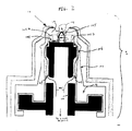
- Fig. 1 is a cross-sectional view along the length of aerosol dispenser including one embodiment of a nozzle mechanism according to the present invention.
- Fig. 2 is a cross-sectional view illustrating the flow path of liquid through the fluid communication path between the liquid reservoir and the nozzle mechanism of the aerosol dispenser shown in Fig. 1.
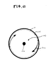
- Fig. 3 is a cross-sectional view along line A-A shown in Fig. 1.
- Fig. 4A is an enlarged cross-sectional view showing one stage of deformation of a valve in the nozzle mechanism according to the present invention shown in Fig. 1.
- Fig. 4B is an enlarged cross-sectional view showing another stage of deformation of the valve in the nozzle mechanism according to the present invention shown in Fig. 1.
- Fig. 5A is an enlarged cross-sectional view showing one stage of deformation of a valve in the body portion of the aerosol dispenser shown in Fig. 1.
- Fig. 5B is an enlarged cross-sectional view showing another stage of deformation of the valve in the body portion of the aerosol dispenser shown in Fig. 1.
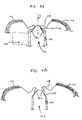
- Fig. 6A is a cross-sectional view showing a second embodiment of the nozzle mechanism according to the present invention.
- Fig. 6B is a cross-sectional view along line B-B shown in Fig. 6A.
- an aerosol-type dispenser system including a first exemplary embodiment of an aerosol tip or nozzle mechanism 2 according to the present invention is indicated generally at 1.
- the first exemplary embodiment of the aerosol tip mechanism 2 includes a flexible nozzle portion 10 having an outlet portion 108 and a fluid channel or swirling channel 104, a rigid shaft 102 received within the flexible nozzle portion 10, and a rigid external housing 101 surrounding the flexible nozzle portion 10 and exposing the outlet portion 108.
- the rigid shaft 102 interfaces the interior of the outlet portion 108 to form a first normally-closed valve 105, as well as to define a swirling chamber or collecting chamber 103 for liquid which has been channeled from a liquid reservoir, prior to being discharged via the outlet portion 108 of the aerosol tip mechanism 2.
- the swirling channel or fluid channel 104 includes gaps between walls 1021a and 1021b circumferentially surrounding the rigid shaft 102.
- the swirling channel 104 which is described in further detail below, channels fluid into the swirling chamber 103.
- a second exemplary embodiment of the aerosol tip or nozzle mechanism 2 according to the present invention is shown in Figs. 6A and 6B.
- the second exemplary embodiment is substantially similar to the first exemplary embodiment, with one exception.
- the second exemplary embodiment of the aerosol tip or nozzle mechanism does not include walls 1021a and 1021b circumferentially surrounding the rigid shaft 102. Accordingly, in the second embodiment shown in Figs. 6A and 6B, the swirling channel 104 is simply an integral part of the swirling chamber 103.
- the first exemplary embodiment of the aerosol tip or nozzle mechanism 2 is coupled to a flexible body portion 107 which as a substantially tubular shape and a wall thickness which decreases from the bottom of the body portion toward the flexible nozzle portion 10, along the elongated axis of symmetry of the body portion.
- the rigid shaft 102 received within the flexible nozzle portion 10 extends down into the flexible body portion 107 so that a second portion 102a of the rigid shaft interfaces the flexible body portion 107 to form a second normally-closed valve 106.
- the fluid communication path 201 of liquid from the liquid reservoir to the outlet portion 108 successively traverses the first and second normally-closed valves 105 and 106, respectively.
- a pump mechanism 110 of the dispenser system acting in concert with a pump-body portion 111 of the dispenser system, channels the liquid from the liquid reservoir along the fluid communication path 201 by application of pressure.
- the nozzle mechanism according to the present invention is intended to be used in conjunction with a wide variety of liquid dispensing systems, one example of which is illustrated in applicant's commonly owned U.S. patent application Serial Number 08/534,609 filed on September 27, 1995, entitled “Fluid Pump Without Dead Volume,” which is expressly incorporated herein by reference. Accordingly, it should be understood that the pump mechanism 110 and the pump-body portion 111 of the dispenser system shown in Figs. 1 and 2 are merely exemplary and generic representation of a wide variety of dispensing systems.
- the liquid from the liquid reservoir is initially channeled through a circumferential channel or groove 109 formed on the exterior of the second portion 102a of the rigid shaft.
- a threshold pressure sufficient to radially deform the flexible body portion 137
- a portion 501 of the flexible body portion 107 forming a lower segment of the second normally-closed valve 106 is radially deformed by the liquid, thereby opening the second normally-closed valve 106, as shown in Fig. 5A.
- the lower segment 501 of the valve 106 is substantially closed by the time the liquid has reached the upper segment 502. Because the energy required to open the lower segment 501 of the valve 106 is greater than the energy required to open the upper segment 502, the liquid is naturally biased to maintain its forward movement through the second valve 106 in the flexible body portion 107 once the lower segment 501 has been opened. In this manner, the second normally-closed valve 106 ensures liquid movement only in the direction towards the flexible nozzle portion 10.
- the liquid in the fluid communication path 201 has traversed the second normally-closed valve 106, the liquid then enters the fluid channel 104 within the flexible nozzle portion 10 of the first embodiment of the aerosol tip mechanism 2, as shown in Figs. 1, 2 and 3.
- the fluid channel 104 which defines a portion of the fluid communication path 201 between the liquid reservoir and the collecting chamber 103, is circumferentially positioned within the flexible nozzle portion, as shown in Fig. 3.
- the circumferentially positioned fluid channel 104 creates swirling action of the liquid, indicated in Fig. 3 by the directional arrow 301, as it is channeled into the swirling chamber 103.
- the liquid directly enters the swirling chamber 103 via the space 601 once the liquid in the fluid communication path 201 has traversed the second normally-closed valve 106.
- the swirling action of the liquid is maintained in the swirling chamber until the liquid is discharged via the outlet portion 108, the mechanics of which discharging action is described in detail below.
- the liquid in the swirling chamber is discharged via the outlet portion 108 when the liquid pressure reaches a threshold pressure sufficient to radially deform the outlet portion 108 forming the first normally-closed valve 105.
- the liquid movement through the first normally-closed valve 105 involves sequential deformation of segments of the outlet portion 108.
- a portion 401 of the outlet portion 108 forming a lower segment of the first normally-closed valve 105 is radially deformed by the liquid, thereby opening the first normally-closed valve 105.
- the wall thickness of the outlet portion 108 decreases from the lower segment 401 towards the upper segment 402 of the first normally-closed valve 105, i.e., along the elongated axis of symmetry S of the aerosol tip or nozzle mechanism. Due to this steady decrease in wall thickness, the lower segment 401 of the valve 105 is substantially closed by the time the liquid has reached the upper segment 402, as shown in Figs. 4A and 4B. Because the energy required to open the lower segment 401 of the valve 105 is greater than the energy requited to open the upper segment 402, the liquid is naturally biased to maintain its forward movement through the first valve 105 in the outlet portion 108 once the lower segment 401 has been opened. Accordingly, the valve 105 ensures liquid movement only in the direction towards the exterior tip of the nozzle portion 10.
- the outlet portion 108 During the discharge of liquid through the outlet portion 108, the only segment of the flexible nozzle portion 10 which experiences deformation along the elongated axis of symmetry S of the aerosol tip or nozzle mechanism is the outlet portion 108.
- the remaining segments of the flexible nozzle portion are prevented by the rigid housing 101 from deformation along the elongated axis of symmetry S.
- the outlet portion 108 does not exert a force along the axis S on the rigid shaft 102, i.e., the outlet portion 108 does not rub the rigid shaft during opening or closing of the first valve 105. Accordingly, because of the absence of any rubbing contact between the outlet portion 108 and the rigid shaft 102, the chances of contaminants entering the swirling chamber 103 are minimized.
- One advantage of the aerosol tip or nozzle mechanism according to the present invention is the above-described prevention of axial deformation of the flexible nozzle portion 10 by the rigid housing 101. Because the flexible nozzle portion 10, with the exception of the outlet portion 108, experiences substantially no deformation along the elongated axis of symmetry S shown in Fig. 4A, the physical profile of the fluid channel 104, which induces swirling action of the liquid channeled into the swirling chamber 103, is maintained during liquid discharge. An axial deformation of the flexible nozzle portion 10 along the direction of liquid discharge would deform the fluid channel 104, which in turn would prevent the swirling action from occurring.
- the flexible nozzle portion 10, the flexible body portion 107 and the pump-body portion 111 may be made of any one of several materials well known in the art, including butadiene polyethylene styrene (KRATON TM ), polyethylene, polyurethane or other plastic materials, thermoplastic elastomers or other elastic materials.
- KRATON TM is particularly well suited for this purpose because of its characteristic resistance to permanent deformation, or "creep," which typically occurs with passage of time.
- an aerosol-type dispensing system incorporating the nozzle mechanism according to the present invention can be made using only three discrete parts: the rigid housing 101; an integral, flexible piece encompassing the flexible nozzle portion 10, the flexible body portion 107 and the pump-body portion 111; and the rigid shaft 102 formed integrally with the pump mechanism 110. Because only three discrete parts are required, the cost and complexity of manufacturing an aerosol-type dispensing system is significantly reduced.
- the first normally-closed, one-way valve 105 with its decreasing wall thickness of the outlet portion 108 substantially eliminates the possibility that liquid in the nozzle mechanism will come in contact with ambient air and subsequently return to the interior portion of the nozzle mechanism. Due to the decreasing wall thickness of the outlet portion 108, the liquid is naturally biased to maintain its forward movement through the first valve 105 in the outlet portion 108 once the thicker base portion of the valve has been opened. Accordingly, the outlet portion 108 has a substantially zero "dead volume,” i.e., a space in which liquid that has been previously exposed to ambient air can remain.
- Still another advantage of the aerosol tip or nozzle mechanism according to the present invention is that the outlet portion 108 does not rub the rigid shaft 102 during opening or closing of the first valve 105. Accordingly, because of the absence of any rubbing contact between the outlet portion 108 and the rigid shaft 102, the chances of contaminants entering the swirling chamber 103 are minimized.
- Still another advantage of the aerosol tip or nozzle mechanism according to the present invention is the presence of multiple valves along the fluid communication path leading to the outlet portion 108.
- the second normally-closed valve positioned along the fluid communication path between the liquid reservoir and the outlet adds further assurances that liquid in the liquid reservoir will not be contaminated by liquid that may have been accidentally exposed to ambient air and subsequently reintroduced into the nozzle mechanism. Because the first and second normally-closed valves are positioned along the fluid communication path to open sequentially, and hence asynchronously, during fluid communication leading to discharge through the outlet, failure of either one of the valves will not affect the integrity of the nozzle mechanism to prevent contamination of the liquid in the liquid reservoir.
Landscapes
- Chemical & Material Sciences (AREA)
- Dispersion Chemistry (AREA)
- Engineering & Computer Science (AREA)
- Mechanical Engineering (AREA)
- Containers And Packaging Bodies Having A Special Means To Remove Contents (AREA)
- Nozzles (AREA)
Applications Claiming Priority (2)
| Application Number | Priority Date | Filing Date | Title |
|---|---|---|---|
| US927221 | 1997-09-10 | ||
| US08/927,221 US5855322A (en) | 1997-09-10 | 1997-09-10 | System and method for one-way spray aerosol tip |
Publications (3)
| Publication Number | Publication Date |
|---|---|
| EP0906786A2 true EP0906786A2 (de) | 1999-04-07 |
| EP0906786A3 EP0906786A3 (de) | 2000-11-08 |
| EP0906786B1 EP0906786B1 (de) | 2003-12-03 |
Family
ID=25454418
Family Applications (1)
| Application Number | Title | Priority Date | Filing Date |
|---|---|---|---|
| EP98307246A Expired - Lifetime EP0906786B1 (de) | 1997-09-10 | 1998-09-08 | System und Verfahren für Sprüh- oder Aerosolspitze mit Einweg-Strömung |
Country Status (11)
| Country | Link |
|---|---|
| US (2) | US5855322A (de) |
| EP (1) | EP0906786B1 (de) |
| JP (1) | JP4074949B2 (de) |
| KR (1) | KR100578444B1 (de) |
| AR (1) | AR015436A1 (de) |
| AT (1) | ATE255469T1 (de) |
| AU (1) | AU732591B2 (de) |
| BR (1) | BR9803401A (de) |
| CA (1) | CA2246294C (de) |
| DE (1) | DE69820189T2 (de) |
| ES (1) | ES2212228T3 (de) |
Families Citing this family (44)
| Publication number | Priority date | Publication date | Assignee | Title |
|---|---|---|---|---|
| FR2773784B1 (fr) * | 1998-01-16 | 2000-03-24 | Valois Sa | Tete de pulverisation pour un distributeur de produit fluide |
| DE19849687A1 (de) * | 1998-10-28 | 2000-05-04 | Valeo Auto Electric Gmbh | Düsenelement für eine Scheibenwaschanlage eines Kraffahrzeuges |
| FR2792552B1 (fr) * | 1999-04-20 | 2002-04-19 | Valois Sa | Tete de pulverisation de produit fluide comportant un obturateur ameliore |
| US6254579B1 (en) | 1999-11-08 | 2001-07-03 | Allergan Sales, Inc. | Multiple precision dose, preservative-free medication delivery system |
| US6302101B1 (en) | 1999-12-14 | 2001-10-16 | Daniel Py | System and method for application of medicament into the nasal passage |
| US6398766B1 (en) * | 1999-12-27 | 2002-06-04 | Vista Innovations, Inc. | Eye wash system |
| US6524287B1 (en) | 2000-10-10 | 2003-02-25 | Advanced Medical Optics | Housing apparatus with rear activated return button for instilling a medication into an eye |
| US6533764B1 (en) | 2000-11-06 | 2003-03-18 | Allergan, Inc. | Twist housing apparatus for instilling a medication into an eye |
| US6415957B1 (en) * | 2000-11-27 | 2002-07-09 | S. C. Johnson & Son, Inc. | Apparatus for dispensing a heated post-foaming gel |
| US6543703B2 (en) * | 2000-12-26 | 2003-04-08 | William S. Blake | Flexible face non-clogging actuator assembly |
| US6506183B2 (en) | 2001-02-02 | 2003-01-14 | Advanced Medical Optics | One shot actuation housing apparatus for instilling a medication into an eye |
| US6685109B2 (en) * | 2001-09-24 | 2004-02-03 | Daniel Py | System and method for a two piece spray nozzle |
| GB2411609B (en) * | 2001-09-24 | 2006-02-22 | Py Daniel C | Method of controlling the particle size of aerosol discharged fluid |
| EP1496832A2 (de) * | 2002-04-10 | 2005-01-19 | Disop-Nordic Holding APS | Röhre mit selbstschliessmechanismus für flüssigkeitsbehälter |
| US6609666B1 (en) * | 2002-07-24 | 2003-08-26 | William Sydney Blake | Unitary over-mold non-clog system with positive shutoff |
| DE10315934B4 (de) * | 2003-04-02 | 2005-08-04 | Ing. Erich Pfeiffer Gmbh | Austragkopf für eine Dosiervorrichtung |
| CA2526362C (en) * | 2003-05-20 | 2012-10-09 | James F. Collins | Ophthalmic drug delivery system |
| US8545463B2 (en) * | 2003-05-20 | 2013-10-01 | Optimyst Systems Inc. | Ophthalmic fluid reservoir assembly for use with an ophthalmic fluid delivery device |
| US20050056708A1 (en) * | 2003-09-12 | 2005-03-17 | Castillo Higareda Jose De Jesus | Apparatus for inducing turbulence in a fluid and method of manufacturing same |
| CN1901966A (zh) * | 2003-11-14 | 2007-01-24 | 因斯蒂尔医学技术有限公司 | 输送装置及输送方法 |
| US7264142B2 (en) | 2004-01-27 | 2007-09-04 | Medical Instill Technologies, Inc. | Dispenser having variable-volume storage chamber and depressible one-way valve assembly for dispensing creams and other substances |
| WO2006037112A2 (en) | 2004-09-27 | 2006-04-06 | Medical Instill Technologies, Inc. | Laterally-actuated dispenser with one- way valve for storing and dispensing metered amounts of substances |
| GB0515592D0 (en) | 2005-07-28 | 2005-09-07 | Glaxo Group Ltd | Nozzle for a nasal inhaler |
| FR2902675B1 (fr) * | 2006-06-21 | 2008-09-12 | Lvmh Rech | Buse de distribution de produit de fluide et dispositif de distribution de produit de fluide comprenant une telle buse |
| WO2008061041A2 (en) * | 2006-11-11 | 2008-05-22 | Medical Instill Technologies, Inc. | Multiple dose delivery device with manually depressible actuator and one-way valve for storing and dispensing substances, and related method |
| FR2912071B1 (fr) * | 2007-02-05 | 2011-03-18 | De La Mer Laboratoire | Embout de pulverisation,container unidose pulverisateur et kit de pulverisation unidose. |
| CA2688689C (en) * | 2007-05-16 | 2015-06-30 | Mystic Pharmaceuticals, Inc. | Combination unit dose dispensing containers |
| US20090212133A1 (en) * | 2008-01-25 | 2009-08-27 | Collins Jr James F | Ophthalmic fluid delivery device and method of operation |
| FR2933680B1 (fr) * | 2008-07-11 | 2013-01-18 | Valois Sa | Pompe de distribution de produit fluide |
| KR101029747B1 (ko) | 2008-09-30 | 2011-04-19 | (주)프로템 | 건조기의 플로팅 노즐 |
| JP2013531548A (ja) | 2010-07-15 | 2013-08-08 | コリンシアン オフサルミック,インコーポレイティド | 遠隔治療及び遠隔モニタリングを実施する方法及びシステム |
| US10154923B2 (en) | 2010-07-15 | 2018-12-18 | Eyenovia, Inc. | Drop generating device |
| EP2485691B1 (de) | 2010-07-15 | 2020-03-18 | Eyenovia, Inc. | Verabreichung einer augenmedizin |
| AU2011278934B2 (en) | 2010-07-15 | 2015-02-26 | Eyenovia, Inc. | Drop generating device |
| JP6105621B2 (ja) | 2011-12-12 | 2017-03-29 | アイノビア,インコーポレイティド | 高弾性高分子エジェクタ機構、エジェクタ装置及びそれらの使用方法 |
| US9415401B2 (en) | 2012-04-04 | 2016-08-16 | Alternative Packaging Solutions Llc | One turn actuated duration spray pump mechanism |
| DE102013215599B4 (de) * | 2013-08-07 | 2017-12-07 | Aptar Radolfzell Gmbh | Pumpeinrichtung und Spender für flüssige oder pastöse Medien |
| CN108602080B (zh) * | 2015-12-04 | 2022-06-24 | 美德斯普瑞公司 | 流体喷雾器 |
| DE102017104740A1 (de) | 2017-03-07 | 2018-09-13 | Ursatec Verpackung Gmbh | Fluidspender |
| DE102017104739A1 (de) | 2017-03-07 | 2018-09-13 | Ursatec Verpackung Gmbh | Fluidspender |
| JP7227163B2 (ja) | 2017-06-10 | 2023-02-21 | アイノビア,インコーポレイティド | 流体を取扱い、目に流体を送出するための方法および装置 |
| US11123220B1 (en) | 2017-11-21 | 2021-09-21 | CryoXcel, LLC | Gas delivery system for cryochamber |
| FR3078271B1 (fr) * | 2018-02-27 | 2022-08-05 | Albea Services | Tete de distribution a chambre tourbillonnaire etagee pour un systeme de distribution |
| US12161585B2 (en) | 2019-12-11 | 2024-12-10 | Eyenovia, Inc. | Systems and devices for delivering fluids to the eye and methods of use |
Family Cites Families (17)
| Publication number | Priority date | Publication date | Assignee | Title |
|---|---|---|---|---|
| US3739952A (en) * | 1971-07-09 | 1973-06-19 | Gillette Co | Intermittent dispensing device |
| US4313569A (en) * | 1980-05-27 | 1982-02-02 | Ethyl Products Company | Fluid dispenser method and apparatus |
| DE3339180C2 (de) * | 1983-10-28 | 1993-10-14 | Pfeiffer Erich Gmbh & Co Kg | Austragvorrichtung für Medien |
| US4623337A (en) * | 1984-03-08 | 1986-11-18 | Alpha Group, Inc. | Liquid dispensing apparatus |
| US5133702A (en) * | 1987-11-06 | 1992-07-28 | O.P.T.I.C. | Ocular treatment apparatus |
| US4981479A (en) * | 1987-11-06 | 1991-01-01 | Py Daniel C | Ocular treatment apparatus |
| US4946452A (en) * | 1987-11-06 | 1990-08-07 | Py Daniel C | Ocular treatment apparatus |
| EP0378935B1 (de) * | 1988-12-20 | 1992-09-23 | Societe Technique De Pulverisation (S.T.E.P.) | Vorrichtung zum Spenden einer Flüssigkeit oder einer Creme in Tropfen kleinen Volumens |
| WO1993002729A1 (en) * | 1990-07-12 | 1993-02-18 | Habley Medical Technology Corporation | Super atomizing nonchlorinated fluorocarbon medication inhaler |
| DE4041136C2 (de) * | 1990-12-21 | 1994-06-30 | Andris Raimund Gmbh & Co Kg | Dosier- und Spraypumpe zur Abgabe flüssiger, niederviskoser und pastöser Stoffe |
| GB9114080D0 (en) * | 1991-06-28 | 1991-08-14 | Weston Terence E | Atomising valve |
| WO1993010852A1 (en) * | 1991-12-02 | 1993-06-10 | Self-Instill & Co., Inc. | Apparatus for applying medicament to an eye |
| WO1993013866A1 (en) * | 1992-01-21 | 1993-07-22 | Wade Manufacturing Co. | Pulsator for irrigation systems and the like |
| US5401259A (en) * | 1992-04-06 | 1995-03-28 | Py Daniel C | Cartridge for applying medicament to an eye |
| US5320845A (en) * | 1993-01-06 | 1994-06-14 | Py Daniel C | Apparatus for delivering multiple medicaments to an eye without premixing in the apparatus |
| US5358179A (en) * | 1993-08-18 | 1994-10-25 | The Procter & Gamble Company | Atomization systems for high viscosity products |
| FR2723618B1 (fr) * | 1994-08-11 | 1996-10-31 | Sofab | Pompe a membrane |
-
1997
- 1997-09-10 US US08/927,221 patent/US5855322A/en not_active Expired - Lifetime
-
1998
- 1998-09-01 CA CA002246294A patent/CA2246294C/en not_active Expired - Fee Related
- 1998-09-08 AT AT98307246T patent/ATE255469T1/de not_active IP Right Cessation
- 1998-09-08 AR ARP980104470A patent/AR015436A1/es unknown
- 1998-09-08 EP EP98307246A patent/EP0906786B1/de not_active Expired - Lifetime
- 1998-09-08 DE DE69820189T patent/DE69820189T2/de not_active Expired - Lifetime
- 1998-09-08 ES ES98307246T patent/ES2212228T3/es not_active Expired - Lifetime
- 1998-09-09 JP JP25572098A patent/JP4074949B2/ja not_active Expired - Fee Related
- 1998-09-09 KR KR1019980037118A patent/KR100578444B1/ko not_active Expired - Fee Related
- 1998-09-09 BR BR9803401-4A patent/BR9803401A/pt not_active Application Discontinuation
- 1998-09-09 AU AU83216/98A patent/AU732591B2/en not_active Ceased
- 1998-11-16 US US09/192,843 patent/US6053433A/en not_active Expired - Lifetime
Also Published As
| Publication number | Publication date |
|---|---|
| DE69820189T2 (de) | 2004-09-16 |
| CA2246294C (en) | 2009-01-20 |
| DE69820189D1 (de) | 2004-01-15 |
| ES2212228T3 (es) | 2004-07-16 |
| ATE255469T1 (de) | 2003-12-15 |
| HK1019315A1 (en) | 2000-02-03 |
| KR100578444B1 (ko) | 2006-07-25 |
| EP0906786A3 (de) | 2000-11-08 |
| AU8321698A (en) | 1999-03-25 |
| BR9803401A (pt) | 2001-03-20 |
| CA2246294A1 (en) | 1999-03-10 |
| AU732591B2 (en) | 2001-04-26 |
| US6053433A (en) | 2000-04-25 |
| KR19990029656A (ko) | 1999-04-26 |
| US5855322A (en) | 1999-01-05 |
| JPH11189282A (ja) | 1999-07-13 |
| EP0906786B1 (de) | 2003-12-03 |
| JP4074949B2 (ja) | 2008-04-16 |
| AR015436A1 (es) | 2001-05-02 |
Similar Documents
| Publication | Publication Date | Title |
|---|---|---|
| US5855322A (en) | System and method for one-way spray aerosol tip | |
| EP1237607B1 (de) | System zum verabreichen von medikamenten in die nasenpassage | |
| AU730007B2 (en) | Dispenser for media | |
| JP3355459B2 (ja) | 流体を噴霧または分与する装置 | |
| US6516976B2 (en) | Dosing pump for liquid dispensers | |
| CN100540148C (zh) | 封闭构件 | |
| JPH06191571A (ja) | 液体物質又はクリームもしくはペースト形態の物質を分配するためのディスペンサ | |
| CZ295103B6 (cs) | Zařízení miniaturní konstrukce pro tlakování tekutiny, rozprašovač pro rozprašování tekutiny a čerpací zařízení s vratným pohybem pro vytváření vysokého tlaku v tekutině | |
| EP0784512B1 (de) | Pumpe mit verformbarer pumpenkammer und verdrängungskörper | |
| EP1597173B1 (de) | Dosierventile für spender | |
| EP0998355B1 (de) | Druckknopf mit einer beweglichen düse zum austragen von unter druck stehenden flüssigkeiten | |
| HK1019315B (en) | System and method for one-way spray/aerosol tip | |
| EP0754499A2 (de) | Sprühvorrichtung | |
| GB2340477A (en) | Metering valve | |
| MXPA98007337A (en) | System and method for spray tip / spray of a p | |
| EP4703045A1 (de) | Austragkopf und fluidspender mit einem solchen austragkopf | |
| CA2592954C (en) | System and method for application of medicament into the nasal passage | |
| AU2002235223A1 (en) | Dosing pump for liquid dispensers |
Legal Events
| Date | Code | Title | Description |
|---|---|---|---|
| PUAI | Public reference made under article 153(3) epc to a published international application that has entered the european phase |
Free format text: ORIGINAL CODE: 0009012 |
|
| AK | Designated contracting states |
Kind code of ref document: A2 Designated state(s): AT BE CH DE DK ES FR GB IE IT LI NL PT SE |
|
| AX | Request for extension of the european patent |
Free format text: AL;LT;LV;MK;RO;SI |
|
| PUAL | Search report despatched |
Free format text: ORIGINAL CODE: 0009013 |
|
| AK | Designated contracting states |
Kind code of ref document: A3 Designated state(s): AT BE CH CY DE DK ES FI FR GB GR IE IT LI LU MC NL PT SE |
|
| AX | Request for extension of the european patent |
Free format text: AL;LT;LV;MK;RO;SI |
|
| RIC1 | Information provided on ipc code assigned before grant |
Free format text: 7B 05B 11/00 A, 7B 05B 1/32 B, 7B 05B 1/34 B, 7B 65D 47/20 B |
|
| 17P | Request for examination filed |
Effective date: 20010411 |
|
| AKX | Designation fees paid |
Free format text: AT BE CH DE DK ES FR GB IE IT LI NL PT SE |
|
| 17Q | First examination report despatched |
Effective date: 20020508 |
|
| GRAH | Despatch of communication of intention to grant a patent |
Free format text: ORIGINAL CODE: EPIDOS IGRA |
|
| GRAS | Grant fee paid |
Free format text: ORIGINAL CODE: EPIDOSNIGR3 |
|
| GRAA | (expected) grant |
Free format text: ORIGINAL CODE: 0009210 |
|
| AK | Designated contracting states |
Kind code of ref document: B1 Designated state(s): AT BE CH DE DK ES FR GB IE IT LI NL PT SE |
|
| PG25 | Lapsed in a contracting state [announced via postgrant information from national office to epo] |
Ref country code: NL Free format text: LAPSE BECAUSE OF FAILURE TO SUBMIT A TRANSLATION OF THE DESCRIPTION OR TO PAY THE FEE WITHIN THE PRESCRIBED TIME-LIMIT Effective date: 20031203 Ref country code: LI Free format text: LAPSE BECAUSE OF FAILURE TO SUBMIT A TRANSLATION OF THE DESCRIPTION OR TO PAY THE FEE WITHIN THE PRESCRIBED TIME-LIMIT Effective date: 20031203 Ref country code: CH Free format text: LAPSE BECAUSE OF FAILURE TO SUBMIT A TRANSLATION OF THE DESCRIPTION OR TO PAY THE FEE WITHIN THE PRESCRIBED TIME-LIMIT Effective date: 20031203 Ref country code: AT Free format text: LAPSE BECAUSE OF FAILURE TO SUBMIT A TRANSLATION OF THE DESCRIPTION OR TO PAY THE FEE WITHIN THE PRESCRIBED TIME-LIMIT Effective date: 20031203 |
|
| REG | Reference to a national code |
Ref country code: GB Ref legal event code: FG4D |
|
| REG | Reference to a national code |
Ref country code: CH Ref legal event code: EP |
|
| REG | Reference to a national code |
Ref country code: IE Ref legal event code: FG4D |
|
| REF | Corresponds to: |
Ref document number: 69820189 Country of ref document: DE Date of ref document: 20040115 Kind code of ref document: P |
|
| PG25 | Lapsed in a contracting state [announced via postgrant information from national office to epo] |
Ref country code: DK Free format text: LAPSE BECAUSE OF FAILURE TO SUBMIT A TRANSLATION OF THE DESCRIPTION OR TO PAY THE FEE WITHIN THE PRESCRIBED TIME-LIMIT Effective date: 20040303 |
|
| REG | Reference to a national code |
Ref country code: SE Ref legal event code: TRGR |
|
| NLV1 | Nl: lapsed or annulled due to failure to fulfill the requirements of art. 29p and 29m of the patents act | ||
| REG | Reference to a national code |
Ref country code: CH Ref legal event code: PL |
|
| REG | Reference to a national code |
Ref country code: ES Ref legal event code: FG2A Ref document number: 2212228 Country of ref document: ES Kind code of ref document: T3 |
|
| PGFP | Annual fee paid to national office [announced via postgrant information from national office to epo] |
Ref country code: IE Payment date: 20040928 Year of fee payment: 7 |
|
| ET | Fr: translation filed | ||
| PLBE | No opposition filed within time limit |
Free format text: ORIGINAL CODE: 0009261 |
|
| STAA | Information on the status of an ep patent application or granted ep patent |
Free format text: STATUS: NO OPPOSITION FILED WITHIN TIME LIMIT |
|
| 26N | No opposition filed |
Effective date: 20040906 |
|
| PG25 | Lapsed in a contracting state [announced via postgrant information from national office to epo] |
Ref country code: IE Free format text: LAPSE BECAUSE OF NON-PAYMENT OF DUE FEES Effective date: 20050908 |
|
| REG | Reference to a national code |
Ref country code: IE Ref legal event code: MM4A |
|
| PG25 | Lapsed in a contracting state [announced via postgrant information from national office to epo] |
Ref country code: PT Free format text: LAPSE BECAUSE OF NON-PAYMENT OF DUE FEES Effective date: 20040503 |
|
| BERE | Be: lapsed |
Owner name: *PY DANIEL Effective date: 20100930 |
|
| PGFP | Annual fee paid to national office [announced via postgrant information from national office to epo] |
Ref country code: IT Payment date: 20110219 Year of fee payment: 13 |
|
| PG25 | Lapsed in a contracting state [announced via postgrant information from national office to epo] |
Ref country code: BE Free format text: LAPSE BECAUSE OF NON-PAYMENT OF DUE FEES Effective date: 20100930 |
|
| PGFP | Annual fee paid to national office [announced via postgrant information from national office to epo] |
Ref country code: ES Payment date: 20110128 Year of fee payment: 13 |
|
| PGFP | Annual fee paid to national office [announced via postgrant information from national office to epo] |
Ref country code: BE Payment date: 20110722 Year of fee payment: 13 |
|
| BERE | Be: lapsed |
Owner name: *PY DANIEL Effective date: 20110930 |
|
| PG25 | Lapsed in a contracting state [announced via postgrant information from national office to epo] |
Ref country code: IT Free format text: LAPSE BECAUSE OF NON-PAYMENT OF DUE FEES Effective date: 20110908 |
|
| PG25 | Lapsed in a contracting state [announced via postgrant information from national office to epo] |
Ref country code: BE Free format text: LAPSE BECAUSE OF NON-PAYMENT OF DUE FEES Effective date: 20110930 |
|
| REG | Reference to a national code |
Ref country code: ES Ref legal event code: FD2A Effective date: 20130530 |
|
| PG25 | Lapsed in a contracting state [announced via postgrant information from national office to epo] |
Ref country code: ES Free format text: LAPSE BECAUSE OF NON-PAYMENT OF DUE FEES Effective date: 20110909 |
|
| REG | Reference to a national code |
Ref country code: FR Ref legal event code: PLFP Year of fee payment: 19 |
|
| REG | Reference to a national code |
Ref country code: FR Ref legal event code: PLFP Year of fee payment: 20 |
|
| PGFP | Annual fee paid to national office [announced via postgrant information from national office to epo] |
Ref country code: DE Payment date: 20170905 Year of fee payment: 20 Ref country code: GB Payment date: 20170906 Year of fee payment: 20 Ref country code: FR Payment date: 20170810 Year of fee payment: 20 |
|
| PGFP | Annual fee paid to national office [announced via postgrant information from national office to epo] |
Ref country code: SE Payment date: 20170912 Year of fee payment: 20 |
|
| REG | Reference to a national code |
Ref country code: DE Ref legal event code: R071 Ref document number: 69820189 Country of ref document: DE |
|
| REG | Reference to a national code |
Ref country code: GB Ref legal event code: PE20 Expiry date: 20180907 |
|
| PG25 | Lapsed in a contracting state [announced via postgrant information from national office to epo] |
Ref country code: GB Free format text: LAPSE BECAUSE OF EXPIRATION OF PROTECTION Effective date: 20180907 |