EP0906737A1 - Sheet metal beam - Google Patents
Sheet metal beam Download PDFInfo
- Publication number
- EP0906737A1 EP0906737A1 EP98115592A EP98115592A EP0906737A1 EP 0906737 A1 EP0906737 A1 EP 0906737A1 EP 98115592 A EP98115592 A EP 98115592A EP 98115592 A EP98115592 A EP 98115592A EP 0906737 A1 EP0906737 A1 EP 0906737A1
- Authority
- EP
- European Patent Office
- Prior art keywords
- profile
- material thickness
- wall
- section
- band iron
- Prior art date
- Legal status (The legal status is an assumption and is not a legal conclusion. Google has not performed a legal analysis and makes no representation as to the accuracy of the status listed.)
- Granted
Links
- 239000002184 metal Substances 0.000 title 1
- 229910000831 Steel Inorganic materials 0.000 claims abstract description 52
- 239000010959 steel Substances 0.000 claims abstract description 52
- 239000000463 material Substances 0.000 claims abstract description 40
- XEEYBQQBJWHFJM-UHFFFAOYSA-N Iron Chemical compound [Fe] XEEYBQQBJWHFJM-UHFFFAOYSA-N 0.000 claims description 85
- 229910052742 iron Inorganic materials 0.000 claims description 40
- 238000000034 method Methods 0.000 claims description 11
- 230000015572 biosynthetic process Effects 0.000 claims description 5
- 235000000396 iron Nutrition 0.000 claims 2
- 238000004519 manufacturing process Methods 0.000 description 9
- 239000011324 bead Substances 0.000 description 5
- 238000005452 bending Methods 0.000 description 4
- 238000000465 moulding Methods 0.000 description 3
- 238000010276 construction Methods 0.000 description 2
- 238000010521 absorption reaction Methods 0.000 description 1
- 230000000052 comparative effect Effects 0.000 description 1
- 238000011161 development Methods 0.000 description 1
- 230000018109 developmental process Effects 0.000 description 1
- 238000009434 installation Methods 0.000 description 1
- 239000012778 molding material Substances 0.000 description 1
- 239000002994 raw material Substances 0.000 description 1
- 230000006641 stabilisation Effects 0.000 description 1
- 238000011105 stabilization Methods 0.000 description 1
- 239000007858 starting material Substances 0.000 description 1
- 230000003068 static effect Effects 0.000 description 1
Images


Classifications
-
- E—FIXED CONSTRUCTIONS
- E04—BUILDING
- E04B—GENERAL BUILDING CONSTRUCTIONS; WALLS, e.g. PARTITIONS; ROOFS; FLOORS; CEILINGS; INSULATION OR OTHER PROTECTION OF BUILDINGS
- E04B9/00—Ceilings; Construction of ceilings, e.g. false ceilings; Ceiling construction with regard to insulation
- E04B9/06—Ceilings; Construction of ceilings, e.g. false ceilings; Ceiling construction with regard to insulation characterised by constructional features of the supporting construction, e.g. cross section or material of framework members
- E04B9/065—Ceilings; Construction of ceilings, e.g. false ceilings; Ceiling construction with regard to insulation characterised by constructional features of the supporting construction, e.g. cross section or material of framework members comprising supporting beams having a folded cross-section
-
- A—HUMAN NECESSITIES
- A47—FURNITURE; DOMESTIC ARTICLES OR APPLIANCES; COFFEE MILLS; SPICE MILLS; SUCTION CLEANERS IN GENERAL
- A47B—TABLES; DESKS; OFFICE FURNITURE; CABINETS; DRAWERS; GENERAL DETAILS OF FURNITURE
- A47B96/00—Details of cabinets, racks or shelf units not covered by a single one of groups A47B43/00 - A47B95/00; General details of furniture
- A47B96/14—Bars, uprights, struts, or like supports, for cabinets, brackets, or the like
- A47B96/1433—Hollow members
-
- A—HUMAN NECESSITIES
- A47—FURNITURE; DOMESTIC ARTICLES OR APPLIANCES; COFFEE MILLS; SPICE MILLS; SUCTION CLEANERS IN GENERAL
- A47B—TABLES; DESKS; OFFICE FURNITURE; CABINETS; DRAWERS; GENERAL DETAILS OF FURNITURE
- A47B96/00—Details of cabinets, racks or shelf units not covered by a single one of groups A47B43/00 - A47B95/00; General details of furniture
- A47B96/14—Bars, uprights, struts, or like supports, for cabinets, brackets, or the like
- A47B96/1466—Bars, uprights, struts, or like supports, for cabinets, brackets, or the like with longitudinal grooves
-
- E—FIXED CONSTRUCTIONS
- E04—BUILDING
- E04C—STRUCTURAL ELEMENTS; BUILDING MATERIALS
- E04C3/00—Structural elongated elements designed for load-supporting
- E04C3/02—Joists; Girders, trusses, or trusslike structures, e.g. prefabricated; Lintels; Transoms; Braces
- E04C3/04—Joists; Girders, trusses, or trusslike structures, e.g. prefabricated; Lintels; Transoms; Braces of metal
- E04C3/06—Joists; Girders, trusses, or trusslike structures, e.g. prefabricated; Lintels; Transoms; Braces of metal with substantially solid, i.e. unapertured, web
- E04C3/07—Joists; Girders, trusses, or trusslike structures, e.g. prefabricated; Lintels; Transoms; Braces of metal with substantially solid, i.e. unapertured, web at least partly of bent or otherwise deformed strip- or sheet-like material
-
- F—MECHANICAL ENGINEERING; LIGHTING; HEATING; WEAPONS; BLASTING
- F16—ENGINEERING ELEMENTS AND UNITS; GENERAL MEASURES FOR PRODUCING AND MAINTAINING EFFECTIVE FUNCTIONING OF MACHINES OR INSTALLATIONS; THERMAL INSULATION IN GENERAL
- F16B—DEVICES FOR FASTENING OR SECURING CONSTRUCTIONAL ELEMENTS OR MACHINE PARTS TOGETHER, e.g. NAILS, BOLTS, CIRCLIPS, CLAMPS, CLIPS OR WEDGES; JOINTS OR JOINTING
- F16B12/00—Jointing of furniture or the like, e.g. hidden from exterior
- F16B12/10—Jointing of furniture or the like, e.g. hidden from exterior using pegs, bolts, tenons, clamps, clips, or the like
- F16B12/28—Jointing of furniture or the like, e.g. hidden from exterior using pegs, bolts, tenons, clamps, clips, or the like for metal furniture parts
- F16B12/32—Jointing of furniture or the like, e.g. hidden from exterior using pegs, bolts, tenons, clamps, clips, or the like for metal furniture parts using clamps, clips, wedges, sliding bolts, or the like
-
- F—MECHANICAL ENGINEERING; LIGHTING; HEATING; WEAPONS; BLASTING
- F16—ENGINEERING ELEMENTS AND UNITS; GENERAL MEASURES FOR PRODUCING AND MAINTAINING EFFECTIVE FUNCTIONING OF MACHINES OR INSTALLATIONS; THERMAL INSULATION IN GENERAL
- F16B—DEVICES FOR FASTENING OR SECURING CONSTRUCTIONAL ELEMENTS OR MACHINE PARTS TOGETHER, e.g. NAILS, BOLTS, CIRCLIPS, CLAMPS, CLIPS OR WEDGES; JOINTS OR JOINTING
- F16B37/00—Nuts or like thread-engaging members
- F16B37/04—Devices for fastening nuts to surfaces, e.g. sheets, plates
- F16B37/045—Devices for fastening nuts to surfaces, e.g. sheets, plates specially adapted for fastening in channels, e.g. sliding bolts, channel nuts
-
- E—FIXED CONSTRUCTIONS
- E04—BUILDING
- E04C—STRUCTURAL ELEMENTS; BUILDING MATERIALS
- E04C3/00—Structural elongated elements designed for load-supporting
- E04C3/02—Joists; Girders, trusses, or trusslike structures, e.g. prefabricated; Lintels; Transoms; Braces
- E04C3/04—Joists; Girders, trusses, or trusslike structures, e.g. prefabricated; Lintels; Transoms; Braces of metal
- E04C2003/0404—Joists; Girders, trusses, or trusslike structures, e.g. prefabricated; Lintels; Transoms; Braces of metal beams, girders, or joists characterised by cross-sectional aspects
- E04C2003/0408—Joists; Girders, trusses, or trusslike structures, e.g. prefabricated; Lintels; Transoms; Braces of metal beams, girders, or joists characterised by cross-sectional aspects characterised by assembly or the cross-section
- E04C2003/0421—Joists; Girders, trusses, or trusslike structures, e.g. prefabricated; Lintels; Transoms; Braces of metal beams, girders, or joists characterised by cross-sectional aspects characterised by assembly or the cross-section comprising one single unitary part
-
- E—FIXED CONSTRUCTIONS
- E04—BUILDING
- E04C—STRUCTURAL ELEMENTS; BUILDING MATERIALS
- E04C3/00—Structural elongated elements designed for load-supporting
- E04C3/02—Joists; Girders, trusses, or trusslike structures, e.g. prefabricated; Lintels; Transoms; Braces
- E04C3/04—Joists; Girders, trusses, or trusslike structures, e.g. prefabricated; Lintels; Transoms; Braces of metal
- E04C2003/0404—Joists; Girders, trusses, or trusslike structures, e.g. prefabricated; Lintels; Transoms; Braces of metal beams, girders, or joists characterised by cross-sectional aspects
- E04C2003/0426—Joists; Girders, trusses, or trusslike structures, e.g. prefabricated; Lintels; Transoms; Braces of metal beams, girders, or joists characterised by cross-sectional aspects characterised by material distribution in cross section
- E04C2003/043—Joists; Girders, trusses, or trusslike structures, e.g. prefabricated; Lintels; Transoms; Braces of metal beams, girders, or joists characterised by cross-sectional aspects characterised by material distribution in cross section the hollow cross-section comprising at least one enclosed cavity
-
- E—FIXED CONSTRUCTIONS
- E04—BUILDING
- E04C—STRUCTURAL ELEMENTS; BUILDING MATERIALS
- E04C3/00—Structural elongated elements designed for load-supporting
- E04C3/02—Joists; Girders, trusses, or trusslike structures, e.g. prefabricated; Lintels; Transoms; Braces
- E04C3/04—Joists; Girders, trusses, or trusslike structures, e.g. prefabricated; Lintels; Transoms; Braces of metal
- E04C2003/0404—Joists; Girders, trusses, or trusslike structures, e.g. prefabricated; Lintels; Transoms; Braces of metal beams, girders, or joists characterised by cross-sectional aspects
- E04C2003/0443—Joists; Girders, trusses, or trusslike structures, e.g. prefabricated; Lintels; Transoms; Braces of metal beams, girders, or joists characterised by cross-sectional aspects characterised by substantial shape of the cross-section
- E04C2003/0465—Joists; Girders, trusses, or trusslike structures, e.g. prefabricated; Lintels; Transoms; Braces of metal beams, girders, or joists characterised by cross-sectional aspects characterised by substantial shape of the cross-section square- or rectangular-shaped
Definitions
- the present invention relates to a steel beam profile in Shape of a spar with an approximately box-shaped cross-section, wherein this is made from a band iron by profiling.
- a steel girder profile With such steel girder profiles, one strives to achieve one the highest possible force absorption and bending strength achieve, while keeping it as low as possible Use of materials. If you have a one-piece box beam want to make it more stable, it is the most obvious way, the Make the wall thicker.
- the material thickness is usually uniformly large everywhere and thus when the material thickness increases a correspondingly higher use of materials is necessary.
- Box spars Such a box spar exists in principle from two individual spar shells, each for be profiled. Then the profiled nested two spar shells, d. H. so interlaced that the spars in parts overlap. This gives you in these overlap areas a greater material thickness of the finished spar, while in the other areas, namely where it is not necessary is just the simple material thickness is present.
- the object of the invention is therefore a Steel girder profile of the type mentioned at the outset To provide the one hand greater stability and resilience with as little as possible Material use and the other hand with comparative low workload is to be profiled.
- a solution according to the invention provides this object Steel girder profile of the type mentioned at the beginning with the characteristic features of the main claim.
- the steel girder profile is made from a band iron in one Profiling operation made, the resulting Steel beam profile nevertheless in certain wall sections has greater material thickness than in the rest Wall sections. It makes sense Wall sections with greater material thickness are those that especially to increase the bending moment and thus the Resilience of the steel girder profile contribute.
- one can within the present invention such a steel beam profile manufacture by profiling an output band that areas of greater material thickness and areas has less material thickness.
- This is starting band iron So rolled from the start and can then in only one Profiling process, which is of course usually the same as for the conventional process usually comprises several forming steps, can be formed into the desired steel girder profile.
- Shapes according to a variant of the method according to the invention you turn the steel girder profile from a single one Output band iron that is pre-profiled so that it is roughly middle area a z. B. in the form of a loop or the like. Then this pre-profiled band iron further profiled preferably such that the above-mentioned molding of the Output band iron in the area of the lower wall of the profiled steel girder profile with approximately box-shaped Cross section lies. There is more in the area of this molding Material available, which leads to an increase in Moment of inertia of the finished steel beam profile leads.
- the band iron is preferably profiled in such a way that end regions of the starting band iron partially overlap and these overlapping regions preferably lie in the region of the upper wall of the finished steel girder profile, so that this upper wall is double-layered.
- the present invention further relates to a method for producing a steel girder profile with an approximately box-shaped cross section, which has regions of the wall with a greater material thickness and regions of the wall with a lower material thickness.
- the object of the invention is to provide a method for producing such a steel beam profile that is simpler than the previously known methods.
- the solution is provided by a method according to the invention of the type mentioned with the features of one of claims 2 or 5.
- the methods according to the invention enable the production of steel girder profiles with good static cross-sectional values and therefore good load-bearing behavior with at the same time minimal use of material, which leads to a reduction in the weight of such steel girder profiles.
- the methods according to the invention further enable simple and rapid production of these steel support profiles and therefore lead to reduced production costs.
- Steel beam profiles of this type can be used, for example, in shelf construction. For example, they can be used for shelf spars on pallet racks, where there are naturally high load-bearing requirements.
- the features mentioned in subclaims 4 and 6 relate to further developments of the steel girder profile according to the invention or the manufacturing method. Further advantages of the invention result from the following detailed description.
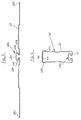
- a profile 10 is produced by roll forming as shown in FIG. 1 is shown.
- the roll forming is usually done in several successive operations until the finished one Profile is rolled.
- the finished profile 10 is shown in Fig. 1. How one see it is an approximately rectangular profile 10 with an upper wall 16 and a lower wall 17 and two Sidewalls. Both the right side wall and the left Sidewall have about in the middle area for stabilization the profile has a bead 13. This is the right one Side wall from an upper side wall section 11 above the bead 13 and a lower side wall section 14 below the bead 13. There is also the left side wall from an upper side wall section 12 above the bead and a lower side wall section 15 below the bead. The respective side wall sections 11, 12 and 14, 15 have as you can see a lower material thickness. Besides, that is Profile seam 18 recognizable, with this profile seam 18th the ends of the outer portions 19a, 19c of the Band iron 19, which is assumed to meet.
- the band iron 19 according to FIG. 2 is mostly made by roll forming profiled several process steps so that the closed rectangular profile 10 according to FIG. 1 is formed. How one 2 areas 19d and 19e can be seen with stronger material thickness already in the band iron 19th provided, which is assumed. These two sections 19d, 19e of greater material thickness form the profile 10 upper wall 16 and the lower wall 17. These sections with greater material thickness are in the finished profile 10 arranged where they are to achieve an increased Bending moments are required while the side walls 12, 15 or 11, 14 are made with a lower material thickness can, so that material for the profile 10 is saved, because the side walls both carry 10 in profile when it is arranged upright as shown in FIG. 1 less to the bending moment.
- FIG. 3 shows another Output band iron 49 from which a steel beam profile according to the Invention can be profiled.
- This output band iron 49 is already pre-profiled from a flat band iron been obtained. With this pre-profiling it has Output band iron 49 a molding approximately in the middle obtained in the form of a loop 49a. As you can see, this is approximately loop-shaped projection 49a formed such that a Section 49d of the band iron in the central area of the Forming approximately parallel to the other largely flat Areas of the band iron runs. Approximately at right angles at the bottom connect to the two side wall sections 49e, 49f of the loop.
- the approximately loop-shaped formation in the area of the lower one Wall 47 of the steel beam profile 40 has applications additional advantages.
- a possible application is in FIG. 5 shown. As you can see, this molding is due to the loop shape similar to a dovetail shape Use the groove to z. B. nuts 41 of helical Insert fasteners 42.
- Such one Steel beam profile 40 can e.g. B. use as a shelf rail find and then has the advantage that an additional Operation for the installation of such a groove or Slot can be omitted.
- the mother 41 of the Fastening screw is seen through a Swiveling movement inserted into the groove and when exercising a tensile force by tightening the screw 42 becomes the nut 41 held in the groove.
Landscapes
- Engineering & Computer Science (AREA)
- Architecture (AREA)
- General Engineering & Computer Science (AREA)
- Civil Engineering (AREA)
- Mechanical Engineering (AREA)
- Structural Engineering (AREA)
- Physics & Mathematics (AREA)
- Electromagnetism (AREA)
- Rod-Shaped Construction Members (AREA)
- Coating With Molten Metal (AREA)
- Supports For Pipes And Cables (AREA)
- Gripping Jigs, Holding Jigs, And Positioning Jigs (AREA)
- Joining Of Building Structures In Genera (AREA)
Abstract
Description
Die vorliegende Erfindung betrifft ein Stahlträgerprofil in Form eines Holms mit etwa kastenförmigem Querschnitt, wobei dieses hergestellt ist aus einem Bandeisen durch Profilieren. Bei solchen Stahlträgerprofilen ist man bestrebt, eine möglichst hohe Kraftaufnahme und Biegefestigkeit zu erreichen, bei gleichzeitig möglichst geringem Materialeinsatz. Wenn man einen einteiligen Kastenholm stabiler gestalten möchte, ist es der naheliegendste Weg, die Wandstärke größer auszubilden. Wird das Stahlträgerprofil aber durch Profilieren aus einem Bandeisen hergestellt, dann ist normalerweise die Materialstärke überall gleichmäßig groß und damit wird bei Erhöhung der Materialstärke ein entsprechend höherer Materialeinsatz notwendig.The present invention relates to a steel beam profile in Shape of a spar with an approximately box-shaped cross-section, wherein this is made from a band iron by profiling. With such steel girder profiles, one strives to achieve one the highest possible force absorption and bending strength achieve, while keeping it as low as possible Use of materials. If you have a one-piece box beam want to make it more stable, it is the most obvious way, the Make the wall thicker. Will the steel beam profile but made by profiling from a band iron, then the material thickness is usually uniformly large everywhere and thus when the material thickness increases a correspondingly higher use of materials is necessary.
Um dies zu Vermeiden hat man bereits sogenannte Schachtelholme entwickelt. Ein solcher Schachtelholm besteht im Prinzip aus zwei einzelnen Holmschalen, die jeweils für sich profiliert werden. Anschließend werden die profilierten beiden Holmschalen miteinander verschachtelt, d. h. so ineinandergelegt, daß sich die Holme in Teilbereichen überlappen. Dadurch hat man in diesen Überlappungsbereichen eine größere Materialstärke des fertigen Holms, während in den übrigen Bereichen und zwar dort, wo es nicht notwendig ist nur die einfache Materialstärke vorhanden ist. Man hat hier zwar den Vorteil eines geringeren Materialeinsatzes, aber es müssen zunächst zwei einzelne Holmschalen profiliert werden. Dies ist ein erhöhter Arbeitsaufwand, da im Prinzip die doppelte Länge an Bandeisen profiliert werden muß wie bei Herstellung eines Stahlträgerprofils aus nur einem Bandeisen.To avoid this you already have so-called Box spars developed. Such a box spar exists in principle from two individual spar shells, each for be profiled. Then the profiled nested two spar shells, d. H. so interlaced that the spars in parts overlap. This gives you in these overlap areas a greater material thickness of the finished spar, while in the other areas, namely where it is not necessary is just the simple material thickness is present. One has here the advantage of using less material, but first two individual spar shells must be profiled become. This is an increased amount of work because, in principle double the length of band iron must be profiled as in Production of a steel girder profile from just one band iron.
Die Aufgabe der Erfindung besteht somit darin, ein Stahlträgerprofil der eingangs genannten Gattung zur Verfügung zu stellen, das einerseits eine größere Stabilität und Belastbarkeit aufweist bei möglichst geringem Materialeinsatz und das andererseits mit vergleichsweise geringem Arbeitsaufwand zu profilieren ist.The object of the invention is therefore a Steel girder profile of the type mentioned at the outset To provide the one hand greater stability and resilience with as little as possible Material use and the other hand with comparative low workload is to be profiled.
Die Lösung dieser Aufgabe liefert ein erfindungsgemäßes Stahlträgerprofil der eingangs genannten Gattung mit den kennzeichnenden Merkmalen des Hauptanspruchs. Erfindungsgemäß wird das Stahlträgerprofil aus einem Bandeisen in einem Profilierarbeitsgang hergestellt, wobei das resultierende Stahlträgerprofil dennoch in bestimmten Wandabschnitten eine größere Materialstärke aufweist als in den übrigen Wandabschnitten. Dabei sind sinnvoller Weise die Wandabschnitte mit größerer Materialstärke solche, die besonders zu einer Erhöhung des Biegemoments und somit der Belastbarkeit des Stahlträgerprofils beitragen. Vorzugsweise handelt es sich im Rahmen der Erfindung um einen hochkant angeordneten kastenförmigen Querschnitt des Stahlträgerprofils und die schmale obere Wand und/oder die schmale untere Wand weisen eine größere Materialstärke auf als einer oder mehrere der rechten bzw. linken Seitenwandabschnitte.A solution according to the invention provides this object Steel girder profile of the type mentioned at the beginning with the characteristic features of the main claim. According to the invention the steel girder profile is made from a band iron in one Profiling operation made, the resulting Steel beam profile nevertheless in certain wall sections has greater material thickness than in the rest Wall sections. It makes sense Wall sections with greater material thickness are those that especially to increase the bending moment and thus the Resilience of the steel girder profile contribute. Preferably is an upright in the context of the invention arranged box-shaped cross section of the Steel beam profile and the narrow top wall and / or the narrow bottom wall are thicker as one or more of the right or left Sidewall sections.
Gemäß einer Lösungsvariante kann man im Rahmen der vorliegenden Erfindung ein solches Stahlträgerprofil herstellen durch Profilieren eines Ausgangsbandeisens, das bereits Bereiche größerer Materialstärke und Bereiche geringerer Materialstärke hat. Dieses Ausgangsbandeisen ist also von vornherein so gewalzt und kann dann in nur einem Profilierarbeitsgang, der natürlich in der Regel wie bei den herkömmlichen Verfahren üblich mehrere Umformschritte umfaßt, zu dem gewünschten Stahlträgerprofil umgeformt werden.According to a solution variant, one can within the present invention such a steel beam profile manufacture by profiling an output band that areas of greater material thickness and areas has less material thickness. This is starting band iron So rolled from the start and can then in only one Profiling process, which is of course usually the same as for the conventional process usually comprises several forming steps, can be formed into the desired steel girder profile.
Gemäß einer Variante des erfindungsgemäßen Verfahrens formt man das Stahlträgerprofil wiederum aus einem einzigen Ausgangsbandeisen, daß so vorprofiliert wird, daß es im etwa mittleren Bereich eine Anformung z. B. in Form einer Schlaufe oder dergleichen aufweist. Anschließend wird dieses vorprofilierte Bandeisen weiterprofiliert und zwar vorzugsweise derart, daß die genannte Anformung des Ausgangsbandeisens im Bereich der unteren Wandung des profilierten Stahlträgerprofils mit etwa kastenförmigen Querschnitt liegt. Im Bereich dieser Anformung ist dann mehr Material vorhanden, was zu einer Erhöhung des Trägheitsmoments des fertigen Stahlträgerprofils führt. Shapes according to a variant of the method according to the invention you turn the steel girder profile from a single one Output band iron that is pre-profiled so that it is roughly middle area a z. B. in the form of a loop or the like. Then this pre-profiled band iron further profiled preferably such that the above-mentioned molding of the Output band iron in the area of the lower wall of the profiled steel girder profile with approximately box-shaped Cross section lies. There is more in the area of this molding Material available, which leads to an increase in Moment of inertia of the finished steel beam profile leads.
Weiter profiliert man vorzugsweise bei dieser Variante das
Bandeisen derart, daß sich jeweils Endbereiche des
Ausgangsbandeisens teilweise überlappen und diese sich
überlappenden Bereiche vorzugsweise im Bereich der oberen
Wandung des fertigen Stahlträgerprofils liegen, so daß diese
obere Wandung doppellagig ist. Dadurch erzielt man im Bereich
dieser doppellagigen oberen Wandung eine zusätzliche Erhöhung
des Trägheitsmoments des Stahlträgerprofils.
Die vorliegende Erfindung betrifft weiterhin ein Verfahren
zur Herstellung eines Stahlträgerprofils mit etwa
kastenförmigen Querschnitt, das Bereiche der Wandung mit
größerer Materialstärke und Bereiche der Wandung mit
geringerer Materialstärke aufweist. Aufgabe der Erfindung ist
es, ein Verfahren zur Herstellung eines solchen
Stahlträgerprofils zu schaffen, das einfacher ist als die
bislang bekannten Verfahren. Die Lösung liefert ein
erfindungsgemäßes Verfahren der genannten Art mit den
Merkmalen eines der Ansprüche 2 oder 5. Die erfindungsgemäßen
Verfahren ermöglichen die Herstellung von Stahlträgerprofilen
mit guten statischen Querschnittswerten und daher gutem
Tragverhalten bei gleichzeitig minimalem Materialeinsatz was
zu einer Verringerung des Gewichts solcher Stahlträgerprofile
führt. Die erfindungsgemäßen Verfahren ermöglichen weiter
eine einfache und rasche Herstellung dieser
Stahlträgerprofile und führen daher zu verringerten
Fertigungskosten. Stahlträgerprofile dieser Art können
beispielsweise im Regalbau zur Anwendung kommen.
Beispielsweise kann man diese für Regalholme von
Palettenregalen verwenden, wo naturgemäß hohe Anforderungen
an die Tragfähigkeit bestehen. Die in den Unteransprüchen 4
und 6 genannten Merkmale betreffen Weiterbildungen des
erfindungsgemäßen Stahlträgerprofils beziehungsweise des
Herstellungsverfahrens. Weitere Vorteile der Erfindung
ergeben sich aus der nachfolgenden Detailbeschreibung. In this variant, the band iron is preferably profiled in such a way that end regions of the starting band iron partially overlap and these overlapping regions preferably lie in the region of the upper wall of the finished steel girder profile, so that this upper wall is double-layered. This results in an additional increase in the moment of inertia of the steel beam profile in the area of this double-layered upper wall.
The present invention further relates to a method for producing a steel girder profile with an approximately box-shaped cross section, which has regions of the wall with a greater material thickness and regions of the wall with a lower material thickness. The object of the invention is to provide a method for producing such a steel beam profile that is simpler than the previously known methods. The solution is provided by a method according to the invention of the type mentioned with the features of one of claims 2 or 5. The methods according to the invention enable the production of steel girder profiles with good static cross-sectional values and therefore good load-bearing behavior with at the same time minimal use of material, which leads to a reduction in the weight of such steel girder profiles. The methods according to the invention further enable simple and rapid production of these steel support profiles and therefore lead to reduced production costs. Steel beam profiles of this type can be used, for example, in shelf construction.
For example, they can be used for shelf spars on pallet racks, where there are naturally high load-bearing requirements. The features mentioned in subclaims 4 and 6 relate to further developments of the steel girder profile according to the invention or the manufacturing method. Further advantages of the invention result from the following detailed description.
Nachfolgend wird die vorliegende Erfindung anhand von Ausführungsbeispielen unter Bezugnahme auf die beiliegenden Zeichnungen näher beschrieben. Dabei zeigen
- Fig. 1
- einen Querschnitt durch ein erfindungsgemäßes Profil;
- Fig. 2
- einen Querschnitt durch ein Bandeisen aus dem ein Profil gemäß Fig. 1 hergestellt wird;
- Fig. 3
- einen Querschnitt durch ein Bandeisen das als Ausgangsmaterial zur Herstellung eines Profils gemäß einer weiteren Variante der Erfindung dient.
- Fig. 4
- einen Querschnitt durch ein erfindungsgemäßes Profil gemäß einer weiteren Variante der Erfindung.
- Fig. 5
- zeigt eine mögliche Anwendung eines in Fig. 4 dargestellten Stahlträgerprofils z. B. im Regalbau.
- Fig. 1
- a cross section through a profile according to the invention;
- Fig. 2
- a cross section through a band iron from which a profile is produced according to FIG. 1;
- Fig. 3
- a cross section through a band iron which serves as the starting material for producing a profile according to a further variant of the invention.
- Fig. 4
- a cross section through an inventive profile according to a further variant of the invention.
- Fig. 5
- shows a possible application of a steel beam profile shown in FIG. B. in shelf construction.
Zunächst wird auf Fig. 1 und 2 Bezug genommen und anhand
dieser eine erste Ausführungsvariante der vorliegenden
Erfindung näher beschrieben. Fig. 1 zeigt einen Querschnitt
durch ein erfindungsgemäßes Profil 10. Dieses wird
hergestellt ausgehend von einem Bandeisen 19 wie es in Fig. 2
im Querschnitt dargestellt ist. Dieses Bandeisen 19 hat
insgesamt fünf Abschnitte, nämlich zwei äußere Abschnitte 19a
bzw. 19c mit einer geringeren Materialstärke und einem
mittleren Abschnitt 19b mit ebenfalls der gleichen geringeren
Materialstärke. Jeweils zwischen den Abschnitten 19a und 19b
mit geringerer Materialstärke liegt ein Abschnitt 19d mit
größerer Materialstärke. Ebenso liegt zwischen dem mittleren
Abschnitt 19b und dem in der Zeichnung rechten äußeren
Abschnitt 19c mit geringerer Materialstärke ein Abschnitt des
Bandeisens 19 mit größerer Materialstärke 19e.First, reference is made to FIGS. 1 and 2 and on the basis
this is a first embodiment of the present
Invention described in more detail. Fig. 1 shows a cross section
by an
Nun wird aus dem in Fig. 2 dargestellten Bandeisen 19 z. B.
durch Rollformen ein Profil 10 hergestellt wie es in Fig. 1
dargestellt ist. Das Rollformen erfolgt in der Regel in
mehreren aufeinanderfolgenden Arbeitsgängen bis das fertige
Profil gewalzt ist.Now from the
Das fertige Profil 10 ist in Fig. 1 dargestellt. Wie man
sieht handelt es sich um ein annähernd rechteckiges Profil 10
mit einer oberen Wand 16 und einer unteren Wand 17 sowie zwei
Seitenwänden. Sowohl die rechte Seitenwand als auch die linke
Seitenwand haben etwa im mittleren Bereich zur Stabilisierung
des Profils je eine Sicke 13. Dadurch besteht die rechte
Seitenwand aus einem oberen Seitenwandabschnitt 11 oberhalb
der Sicke 13 und einem unteren Seitenwandabschnitt 14
unterhalb der Sicke 13. Ebenso besteht die linke Seitenwand
aus einem oberen Seitenwandabschnitt 12 oberhalb der Sicke
und einem unteren Seitenwandabschnitt 15 unterhalb der Sicke.
Die jeweiligen Seitenwandabschnitte 11, 12 bzw. 14, 15 haben
wie man sieht eine geringere Materialstärke. Außerdem ist die
Profilnaht 18 erkennbar, wobei an dieser Profilnaht 18
jeweils die Enden der äußeren Abschnitte 19a, 19c des
Bandeisen 19, von dem ausgegangen wird, zusammentreffen.The
Das Bandeisen 19 gemäß Fig. 2 wird durch Rollformen in meist
mehreren Verfahrensschritten so profiliert, daß das
geschlossene Rechteckprofil 10 gemäß Fig. 1 entsteht. Wie man
aus Fig. 2 erkennen kann sind zwei Bereiche 19d bzw. 19e mit
stärkerer Materialstärke bereits in dem Bandeisen 19
vorgesehen, von dem ausgegangen wird. Diese beiden Abschnitte
19d, 19e größerer Materialstärke bilden in dem Profil 10 die
obere Wandung 16 und die untere Wandung 17. Diese Abschnitte
mit größerer Materialstärke sind also in dem fertigen Profil
10 dort angeordnet, wo sie zur Erzielung eines erhöhten
Biegemoments benötigt werden, während die Seitenwände 12, 15
bzw. 11, 14 in geringerer Materialstärke ausgeführt werden
können, so daß Material für das Profil 10 eingespart wird,
denn die Seitenwände tragen beide im Profil 10, wenn es
hochkant angeordnet wird gemäß der Darstellung in Fig. 1
weniger zum Biegemoment bei. The
Es wird nun nachfolgend ein weiteres Ausführungsbeispiel der
vorliegenden Erfindung unter Bezugnahme auf die Figur 3 bis 5
näher beschrieben. Fig. 3 zeigt ein weiteres
Ausgangsbandeisen 49 aus dem ein Stahlträgerprofil gemäß der
Erfindung profiliert werden kann. Dieses Ausgangsbandeisen 49
ist bereits durch Vorprofilieren aus einem flachen Bandeisen
erhalten worden. Bei diesem Vorprofilieren hat das
Ausgangsbandeisen 49 etwa im mittleren Bereich eine Anformung
in Form einer Schlaufe 49a erhalten. Wie man sieht ist diese
etwa schlaufenförmige Anformung 49a so ausgebildet, daß ein
Abschnitt 49d des Bandeisens im mittleren Bereich der
Anformung etwa parallel zu den übrigen weitgehend flachen
Bereichen des Bandeisens verläuft. Etwa rechtwinklig nach
unten schließen sich daran an die beiden Seitenwandabschnitte
49e, 49f der Schlaufe. Unterhalb dieser Seitenwandabschnitte
49e, 49f ist die Wandung des Bandeisens an beiden Seiten
jeweils noch einmal einwärts abgekröpft, so daß sich eine
Einschnürung ergibt, im Bereich derer die abgekröpften
Abschnitte 49g, 49h des Bandeisens naher aneinanderliegen als
die darüberliegenden Seitenwandabschnitte 49e, 49f.Another embodiment of the
present invention with reference to FIGS. 3 to 5
described in more detail. Fig. 3 shows another
Aus diesem Ausgangsbandeisen 49 wird nun ein
erfindungsgemäßes Stahlträgerprofil 40 profiliert wie es in
Fig. 4 dargestellt ist. Wie man sieht, liegt die
schlaufenförmige Anformung 49a im Bereich der unteren Wandung
47 des fertig profilierten Stahlträgerprofils, so daß dort
sich wesentlich mehr Material befindet als bei einer
einfachen unteren Wandung und das Trägheitsmoment
entsprechend erhöht wird.From this
Wie man weiterhin aus Fig. 4 erkennen kann, erfolgt das
Profilieren des Ausgangsbandeisens 49 derart, daß sich dessen
beide Endabschnitte 49b bzw. 49c im Bereich der oberen
Wandung des Stahlträgerprofils 40 überlappen. Diese obere
Wandung des Stahlträgerprofils 40 ist damit doppellagig mit
der oberen Lage 46, die aus dem Endabschnitt 49c des
Ausgangsbandeisens 49 gebildet wird und mit einer unteren
Lage 44, die aus dem Endabschnitt 49b des Ausgangsbandeisens
49 gebildet wird. Das fertige Stahlträgerprofil 40 hat somit
eine obere doppellagige Wandung, die zu einem erhöhten
Trägheitsmoment des Profils führt, wobei jedoch das
Stahlträgerprofil 40 aus nur einem Ausgangsbandeisen in
aufeinanderfolgenden Profilierarbeitsgängen profiliert werden
kann und somit sowohl der Aufwand im Herstellungsverfahren
als auch die benötigte Materialmenge für das
Stahlträgerprofil minimiert werden. Außerdem hat diese
Variante der Erfindung noch den Vorteil, daß nach dem
Profilieren keine Schweißnaht zur Verbindung wie bei
aneinanderstoßenden Endabschnitten des Ausgangsbandeisens
notwendig ist.As can also be seen from FIG. 4, this takes place
Profiling the
Die etwa schlaufenförmige Anformung im Bereich der unteren
Wandung 47 des Stahlträgerprofils 40 hat bei Anwendungen
weitere Vorteile. Eine mögliche Anwendung ist in Fig. 5
dargestellt. Wie man sieht kann man diese Anformung aufgrund
der Schlaufenform ähnlich wie eine schwalbenschwanzförmige
Nut nutzen, um dort z. B. Muttern 41 von schraubenförmigen
Befestigungselementen 42 einzuschieben. Ein solches
Stahlträgerprofil 40 kann z. B. als Regalholm Verwendung
finden und hat dann den Vorteil, daß ein zusätzlicher
Arbeitsgang für die Anbringung einer solchen Nut bzw. eines
Schlitzes entfallen kann. Die Mutter 41 der
Befestigungsschraube wird wie man sieht durch eine
Schwenkbewegung in die Nut eingeschoben und bei Ausübung
einer Zugkraft durch Anziehen der Schraube 42 wird die Mutter
41 in der Nut gehalten.The approximately loop-shaped formation in the area of the lower one
Claims (6)
wobei das Stahlträgerprofil weiterhin einen hochkant angeordneten kastenförmigen Querschnitt hat,
dadurch gekennzeichnet, daß die schmale obere Wand (16) und/oder die schmale untere Wand (17) eine größere Materialstärke aufweisen als einer oder mehrere der rechten beziehungsweise linken Seitenwandabschnitte (11, 12),
wobei das Stahlträgerprofil hergestellt wurde durch Profilieren eines Ausgangsbandeisens (19), das Bereiche (19d, 19e) größerer Materialstärke und Bereiche (19a, 19b, 19c) geringerer Materialstärke aufweist.Steel girder profile in the form of a spar with an approximately box-shaped cross-section, this being produced starting from band irons by profiling and the steel girder profile having a greater material thickness in at least one wall section than in the other wall sections,
the steel girder profile still has an upright box-shaped cross section,
characterized in that the narrow upper wall (16) and / or the narrow lower wall (17) have a greater material thickness than one or more of the right and left side wall sections (11, 12),
the steel girder profile being produced by profiling an initial strip iron (19) which has areas (19d, 19e) of greater material thickness and areas (19a, 19b, 19c) of lesser material thickness.
Applications Claiming Priority (2)
| Application Number | Priority Date | Filing Date | Title |
|---|---|---|---|
| DE19743643 | 1997-10-02 | ||
| DE19743643A DE19743643A1 (en) | 1997-10-02 | 1997-10-02 | Steel beam profile |
Publications (2)
| Publication Number | Publication Date |
|---|---|
| EP0906737A1 true EP0906737A1 (en) | 1999-04-07 |
| EP0906737B1 EP0906737B1 (en) | 2003-04-16 |
Family
ID=7844441
Family Applications (1)
| Application Number | Title | Priority Date | Filing Date |
|---|---|---|---|
| EP98115592A Expired - Lifetime EP0906737B1 (en) | 1997-10-02 | 1998-08-19 | Sheet metal beam |
Country Status (3)
| Country | Link |
|---|---|
| EP (1) | EP0906737B1 (en) |
| AT (1) | ATE237252T1 (en) |
| DE (2) | DE19743643A1 (en) |
Cited By (9)
| Publication number | Priority date | Publication date | Assignee | Title |
|---|---|---|---|---|
| EP1219756A1 (en) * | 2000-12-29 | 2002-07-03 | Antonello Briosi | Component for load-bearing structures, particularly useful for shelves |
| EP1338716A1 (en) * | 2002-02-22 | 2003-08-27 | HILTI Aktiengesellschaft | Elongated hollow profile for suspending objects |
| EP1479842A1 (en) * | 2003-05-19 | 2004-11-24 | HILTI Aktiengesellschaft | Hollow section |
| ES2220153A1 (en) * | 2000-11-24 | 2004-12-01 | Encofrados Inde-K, S.A. | Improvements to shuttering systems. |
| EP1554444A1 (en) * | 2002-10-23 | 2005-07-20 | Grant Charlwood | A beam |
| EP2065532A1 (en) * | 2007-11-28 | 2009-06-03 | HILTI Aktiengesellschaft | Profile made of a rolled strip |
| WO2010124803A2 (en) * | 2009-04-28 | 2010-11-04 | Kocher Regalbau Gmbh | High-bay warehouse as well as support for a high-bay warehouse and method for producing the support |
| EP2250934A1 (en) * | 2009-05-12 | 2010-11-17 | Heinrich J. Kesseböhmer KG | Cupboard section |
| WO2023029989A1 (en) * | 2021-09-06 | 2023-03-09 | 昊恒(福建)建材科技有限公司 | Integrally formed steel beam |
Families Citing this family (3)
| Publication number | Priority date | Publication date | Assignee | Title |
|---|---|---|---|---|
| DE10154706A1 (en) * | 2001-11-09 | 2003-05-22 | Abb Patent Gmbh | Hollow profile rail for mounting shelves in cupboards is triangular in cross-section, has horizontal and vertical surfaces for supporting shelves and brackets with mounting grooves whose sides slope inwards |
| DE102007056644A1 (en) * | 2007-11-24 | 2009-05-28 | Dr. Ing. H.C. F. Porsche Aktiengesellschaft | Carrier, particularly sill for motor vehicle, comprises three profile sections, which are arranged in longitudinal direction with varying wall thickness or varying bar shape |
| DE102017116856A1 (en) * | 2017-07-26 | 2019-01-31 | Fischerwerke Gmbh & Co. Kg | Mounting rail with a fastener |
Citations (3)
| Publication number | Priority date | Publication date | Assignee | Title |
|---|---|---|---|---|
| FR1532887A (en) * | 1967-07-27 | 1968-07-12 | Neunkircher Eisenwerk Ag | Hollow steel section and its manufacturing process |
| DE3513382A1 (en) * | 1985-04-15 | 1986-10-23 | Moeller automation GmbH, 5303 Bornheim | Load-bearing profiles for assembly installations, supporting structures and conveyor belts, and process for the production thereof |
| US5014487A (en) * | 1989-11-01 | 1991-05-14 | S&K Enterprises, Inc. | Rack beams and method of making same |
Family Cites Families (6)
| Publication number | Priority date | Publication date | Assignee | Title |
|---|---|---|---|---|
| DK125512B (en) * | 1970-11-11 | 1973-03-05 | Kramme & Zeuthen As | Cash drawers, especially for storage racks. |
| SE462173B (en) * | 1985-04-30 | 1990-05-14 | Gunnebo Ab | STUDULAR POSTS |
| US5194199A (en) * | 1991-02-20 | 1993-03-16 | Volkswagen Ag | Method of producing a beam-like structural part having a core of light-weight material |
| US5514432A (en) * | 1993-07-14 | 1996-05-07 | Lisec; Peter | Hollow profile for spacer frames for insulating glass panes |
| DE9400878U1 (en) * | 1994-01-20 | 1994-04-14 | Vulart Riera, Jose Maria, Barcelona | carrier |
| DE19549268C1 (en) * | 1995-12-28 | 1997-07-31 | Mannesmann Ag | Carrier in box construction, in particular crane boom or telescopic boom and method for producing a carrier |
-
1997
- 1997-10-02 DE DE19743643A patent/DE19743643A1/en not_active Ceased
-
1998
- 1998-08-19 EP EP98115592A patent/EP0906737B1/en not_active Expired - Lifetime
- 1998-08-19 DE DE59807944T patent/DE59807944D1/en not_active Expired - Lifetime
- 1998-08-19 AT AT98115592T patent/ATE237252T1/en not_active IP Right Cessation
Patent Citations (3)
| Publication number | Priority date | Publication date | Assignee | Title |
|---|---|---|---|---|
| FR1532887A (en) * | 1967-07-27 | 1968-07-12 | Neunkircher Eisenwerk Ag | Hollow steel section and its manufacturing process |
| DE3513382A1 (en) * | 1985-04-15 | 1986-10-23 | Moeller automation GmbH, 5303 Bornheim | Load-bearing profiles for assembly installations, supporting structures and conveyor belts, and process for the production thereof |
| US5014487A (en) * | 1989-11-01 | 1991-05-14 | S&K Enterprises, Inc. | Rack beams and method of making same |
Cited By (12)
| Publication number | Priority date | Publication date | Assignee | Title |
|---|---|---|---|---|
| ES2220153A1 (en) * | 2000-11-24 | 2004-12-01 | Encofrados Inde-K, S.A. | Improvements to shuttering systems. |
| EP1219756A1 (en) * | 2000-12-29 | 2002-07-03 | Antonello Briosi | Component for load-bearing structures, particularly useful for shelves |
| EP1338716A1 (en) * | 2002-02-22 | 2003-08-27 | HILTI Aktiengesellschaft | Elongated hollow profile for suspending objects |
| EP1554444A1 (en) * | 2002-10-23 | 2005-07-20 | Grant Charlwood | A beam |
| EP1554444A4 (en) * | 2002-10-23 | 2007-07-11 | Grant Charlwood | A beam |
| EP1479842A1 (en) * | 2003-05-19 | 2004-11-24 | HILTI Aktiengesellschaft | Hollow section |
| US7096641B2 (en) | 2003-05-19 | 2006-08-29 | Hilti Aktiengesellschaft | Hollow profile |
| EP2065532A1 (en) * | 2007-11-28 | 2009-06-03 | HILTI Aktiengesellschaft | Profile made of a rolled strip |
| WO2010124803A2 (en) * | 2009-04-28 | 2010-11-04 | Kocher Regalbau Gmbh | High-bay warehouse as well as support for a high-bay warehouse and method for producing the support |
| WO2010124803A3 (en) * | 2009-04-28 | 2011-06-16 | Kocher Regalbau Gmbh | High-bay warehouse as well as support for a high-bay warehouse and method for producing the support |
| EP2250934A1 (en) * | 2009-05-12 | 2010-11-17 | Heinrich J. Kesseböhmer KG | Cupboard section |
| WO2023029989A1 (en) * | 2021-09-06 | 2023-03-09 | 昊恒(福建)建材科技有限公司 | Integrally formed steel beam |
Also Published As
| Publication number | Publication date |
|---|---|
| DE19743643A1 (en) | 1999-04-08 |
| DE59807944D1 (en) | 2003-05-22 |
| ATE237252T1 (en) | 2003-05-15 |
| EP0906737B1 (en) | 2003-04-16 |
Similar Documents
| Publication | Publication Date | Title |
|---|---|---|
| DE69227260T2 (en) | FLAT-ROLLED METAL PROFILE WITH REINFORCING IMPRESSIONS | |
| DE3785529T2 (en) | STRUCTURES FORMED BY COLD LAMINATION, DEVICE AND METHOD FOR PRODUCING THE SAME. | |
| DE69808948T2 (en) | BUMPER AND MANUFACTURING METHOD | |
| DE69320366T2 (en) | LEAFY MATERIAL, METHOD AND ROLLERS FOR USE IN THIS METHOD | |
| DE3513382A1 (en) | Load-bearing profiles for assembly installations, supporting structures and conveyor belts, and process for the production thereof | |
| EP0906737B1 (en) | Sheet metal beam | |
| DE19543414B4 (en) | Process for hot rolling sheet piles with a Z-shaped cross-section | |
| DE2256705A1 (en) | STRUT CONSTRUCTION | |
| EP1335148B1 (en) | Supporting body, in particular for elastically supporting a sitting or lying furniture | |
| DE2827950C2 (en) | ||
| DE3144736A1 (en) | STRETCHMETAL WORKPIECE AND METHOD FOR PRODUCING THE SAME | |
| DD271159A1 (en) | MANUFACTURING PROCESS FOR FASTER METAL PROFILES | |
| DE2154519B2 (en) | Box girders, in particular for storage racks | |
| CH459117A (en) | Method and device for cold drawing of solid wire | |
| DE2343247A1 (en) | METHOD FOR MANUFACTURING ANGLED SHOULDER RIMS | |
| DE2511812A1 (en) | METAL ROD FOR REINFORCED CONCRETE AND METHOD FOR ITS MANUFACTURING | |
| DE3609601A1 (en) | TUBULAR POST | |
| DE2624872A1 (en) | METHOD OF MANUFACTURING UNDIVIDED WHEELS | |
| DE3022085A1 (en) | CONCRETE REINFORCING BAR, ESPECIALLY ANCHOR BAR, AND METHOD FOR THE PRODUCTION THEREOF | |
| DE3515205C2 (en) | ||
| DD145506A5 (en) | PROCESS FOR THE MANUFACTURE OF NAEGELN | |
| DE69621531T2 (en) | Shelf, in particular for metal shelf units | |
| DE10084916B3 (en) | Metal filler for a truss, truss and method for building a truss | |
| EP0525661B1 (en) | Shuttering for concrete construction and method for the manufacturing of the shuttering | |
| WO2017198855A1 (en) | Scaffolding post and method for producing a scaffolding post |
Legal Events
| Date | Code | Title | Description |
|---|---|---|---|
| PUAI | Public reference made under article 153(3) epc to a published international application that has entered the european phase |
Free format text: ORIGINAL CODE: 0009012 |
|
| AK | Designated contracting states |
Kind code of ref document: A1 Designated state(s): AT BE CH CY DE DK ES FI FR GB GR IE IT LI LU MC NL PT SE |
|
| AX | Request for extension of the european patent |
Free format text: AL;LT;LV;MK;RO;SI |
|
| 17P | Request for examination filed |
Effective date: 19990618 |
|
| AKX | Designation fees paid |
Free format text: AT BE CH CY DE DK ES FI FR GB GR IE IT LI LU MC NL PT SE |
|
| AXX | Extension fees paid |
Free format text: AL PAYMENT 19990618;LT PAYMENT 19990618;LV PAYMENT 19990618;MK PAYMENT 19990618;RO PAYMENT 19990618;SI PAYMENT 19990618 |
|
| 17Q | First examination report despatched |
Effective date: 20011212 |
|
| GRAH | Despatch of communication of intention to grant a patent |
Free format text: ORIGINAL CODE: EPIDOS IGRA |
|
| GRAH | Despatch of communication of intention to grant a patent |
Free format text: ORIGINAL CODE: EPIDOS IGRA |
|
| GRAA | (expected) grant |
Free format text: ORIGINAL CODE: 0009210 |
|
| AK | Designated contracting states |
Designated state(s): AT BE CH CY DE DK ES FI FR GB GR IE IT LI LU MC NL PT SE |
|
| AX | Request for extension of the european patent |
Extension state: AL LT LV MK RO SI |
|
| PG25 | Lapsed in a contracting state [announced via postgrant information from national office to epo] |
Ref country code: NL Free format text: LAPSE BECAUSE OF FAILURE TO SUBMIT A TRANSLATION OF THE DESCRIPTION OR TO PAY THE FEE WITHIN THE PRESCRIBED TIME-LIMIT Effective date: 20030416 Ref country code: IT Free format text: LAPSE BECAUSE OF FAILURE TO SUBMIT A TRANSLATION OF THE DESCRIPTION OR TO PAY THE FEE WITHIN THE PRE;WARNING: LAPSES OF ITALIAN PATENTS WITH EFFECTIVE DATE BEFORE 2007 MAY HAVE OCCURRED AT ANY TIME BEFORE 2007. THE CORRECT EFFECTIVE DATE MAY BE DIFFERENT FROM THE ONE RECORDED.SCRIBED TIME-LIMIT Effective date: 20030416 Ref country code: IE Free format text: LAPSE BECAUSE OF NON-PAYMENT OF DUE FEES Effective date: 20030416 Ref country code: GB Free format text: LAPSE BECAUSE OF FAILURE TO SUBMIT A TRANSLATION OF THE DESCRIPTION OR TO PAY THE FEE WITHIN THE PRESCRIBED TIME-LIMIT Effective date: 20030416 Ref country code: FR Free format text: LAPSE BECAUSE OF FAILURE TO SUBMIT A TRANSLATION OF THE DESCRIPTION OR TO PAY THE FEE WITHIN THE PRESCRIBED TIME-LIMIT Effective date: 20030416 Ref country code: FI Free format text: LAPSE BECAUSE OF FAILURE TO SUBMIT A TRANSLATION OF THE DESCRIPTION OR TO PAY THE FEE WITHIN THE PRESCRIBED TIME-LIMIT Effective date: 20030416 |
|
| REG | Reference to a national code |
Ref country code: GB Ref legal event code: FG4D Free format text: NOT ENGLISH |
|
| REG | Reference to a national code |
Ref country code: CH Ref legal event code: EP |
|
| REF | Corresponds to: |
Ref document number: 59807944 Country of ref document: DE Date of ref document: 20030522 Kind code of ref document: P |
|
| REG | Reference to a national code |
Ref country code: IE Ref legal event code: FG4D Free format text: GERMAN |
|
| PG25 | Lapsed in a contracting state [announced via postgrant information from national office to epo] |
Ref country code: SE Free format text: LAPSE BECAUSE OF FAILURE TO SUBMIT A TRANSLATION OF THE DESCRIPTION OR TO PAY THE FEE WITHIN THE PRESCRIBED TIME-LIMIT Effective date: 20030716 Ref country code: PT Free format text: LAPSE BECAUSE OF FAILURE TO SUBMIT A TRANSLATION OF THE DESCRIPTION OR TO PAY THE FEE WITHIN THE PRESCRIBED TIME-LIMIT Effective date: 20030716 Ref country code: GR Free format text: LAPSE BECAUSE OF FAILURE TO SUBMIT A TRANSLATION OF THE DESCRIPTION OR TO PAY THE FEE WITHIN THE PRESCRIBED TIME-LIMIT Effective date: 20030716 Ref country code: DK Free format text: LAPSE BECAUSE OF FAILURE TO SUBMIT A TRANSLATION OF THE DESCRIPTION OR TO PAY THE FEE WITHIN THE PRESCRIBED TIME-LIMIT Effective date: 20030716 |
|
| PG25 | Lapsed in a contracting state [announced via postgrant information from national office to epo] |
Ref country code: LU Free format text: LAPSE BECAUSE OF NON-PAYMENT OF DUE FEES Effective date: 20030819 Ref country code: CY Free format text: LAPSE BECAUSE OF FAILURE TO SUBMIT A TRANSLATION OF THE DESCRIPTION OR TO PAY THE FEE WITHIN THE PRESCRIBED TIME-LIMIT Effective date: 20030819 Ref country code: AT Free format text: LAPSE BECAUSE OF NON-PAYMENT OF DUE FEES Effective date: 20030819 |
|
| PG25 | Lapsed in a contracting state [announced via postgrant information from national office to epo] |
Ref country code: MC Free format text: LAPSE BECAUSE OF NON-PAYMENT OF DUE FEES Effective date: 20030831 Ref country code: LI Free format text: LAPSE BECAUSE OF NON-PAYMENT OF DUE FEES Effective date: 20030831 Ref country code: CH Free format text: LAPSE BECAUSE OF NON-PAYMENT OF DUE FEES Effective date: 20030831 Ref country code: BE Free format text: LAPSE BECAUSE OF NON-PAYMENT OF DUE FEES Effective date: 20030831 |
|
| LTIE | Lt: invalidation of european patent or patent extension |
Effective date: 20030416 |
|
| NLV1 | Nl: lapsed or annulled due to failure to fulfill the requirements of art. 29p and 29m of the patents act | ||
| GBV | Gb: ep patent (uk) treated as always having been void in accordance with gb section 77(7)/1977 [no translation filed] |
Effective date: 20030416 |
|
| PG25 | Lapsed in a contracting state [announced via postgrant information from national office to epo] |
Ref country code: ES Free format text: LAPSE BECAUSE OF FAILURE TO SUBMIT A TRANSLATION OF THE DESCRIPTION OR TO PAY THE FEE WITHIN THE PRESCRIBED TIME-LIMIT Effective date: 20031030 |
|
| REG | Reference to a national code |
Ref country code: IE Ref legal event code: FD4D Ref document number: 0906737E Country of ref document: IE |
|
| PLBE | No opposition filed within time limit |
Free format text: ORIGINAL CODE: 0009261 |
|
| STAA | Information on the status of an ep patent application or granted ep patent |
Free format text: STATUS: NO OPPOSITION FILED WITHIN TIME LIMIT |
|
| BERE | Be: lapsed |
Owner name: *META-REGALBAU G.M.B.H. & CO. K.G. Effective date: 20030831 |
|
| 26N | No opposition filed |
Effective date: 20040119 |
|
| REG | Reference to a national code |
Ref country code: CH Ref legal event code: PL |
|
| EN | Fr: translation not filed | ||
| PGFP | Annual fee paid to national office [announced via postgrant information from national office to epo] |
Ref country code: DE Payment date: 20090831 Year of fee payment: 12 |
|
| REG | Reference to a national code |
Ref country code: DE Ref legal event code: R119 Ref document number: 59807944 Country of ref document: DE Effective date: 20110301 |
|
| PG25 | Lapsed in a contracting state [announced via postgrant information from national office to epo] |
Ref country code: DE Free format text: LAPSE BECAUSE OF NON-PAYMENT OF DUE FEES Effective date: 20110301 |