EP0906560B1 - Verfahren und vorrichtung zur zerstörungsfreien klassifikation - Google Patents
Verfahren und vorrichtung zur zerstörungsfreien klassifikation Download PDFInfo
- Publication number
- EP0906560B1 EP0906560B1 EP97928616A EP97928616A EP0906560B1 EP 0906560 B1 EP0906560 B1 EP 0906560B1 EP 97928616 A EP97928616 A EP 97928616A EP 97928616 A EP97928616 A EP 97928616A EP 0906560 B1 EP0906560 B1 EP 0906560B1
- Authority
- EP
- European Patent Office
- Prior art keywords
- unit
- vibration
- impact
- determination
- timber
- Prior art date
- Legal status (The legal status is an assumption and is not a legal conclusion. Google has not performed a legal analysis and makes no representation as to the accuracy of the status listed.)
- Expired - Lifetime
Links
- 238000000034 method Methods 0.000 title claims abstract description 53
- 238000012360 testing method Methods 0.000 claims abstract description 23
- 230000008569 process Effects 0.000 claims abstract description 6
- 238000005259 measurement Methods 0.000 claims description 9
- 238000001228 spectrum Methods 0.000 claims description 7
- 238000012545 processing Methods 0.000 claims description 6
- 239000000969 carrier Substances 0.000 claims description 5
- 238000010008 shearing Methods 0.000 claims description 5
- 230000004044 response Effects 0.000 claims description 4
- 238000004364 calculation method Methods 0.000 claims description 3
- 238000001514 detection method Methods 0.000 claims description 3
- 238000004519 manufacturing process Methods 0.000 claims description 3
- 230000007246 mechanism Effects 0.000 claims description 3
- 230000009471 action Effects 0.000 claims description 2
- 230000005284 excitation Effects 0.000 claims description 2
- 230000009466 transformation Effects 0.000 claims 2
- 238000006243 chemical reaction Methods 0.000 claims 1
- 238000004088 simulation Methods 0.000 claims 1
- 230000008093 supporting effect Effects 0.000 abstract description 2
- 239000002023 wood Substances 0.000 description 35
- 238000005452 bending Methods 0.000 description 14
- 230000000875 corresponding effect Effects 0.000 description 6
- 238000011156 evaluation Methods 0.000 description 4
- 239000000463 material Substances 0.000 description 3
- 239000000725 suspension Substances 0.000 description 3
- 229910000831 Steel Inorganic materials 0.000 description 2
- 230000001276 controlling effect Effects 0.000 description 2
- 238000005516 engineering process Methods 0.000 description 2
- 230000001939 inductive effect Effects 0.000 description 2
- 125000006850 spacer group Chemical group 0.000 description 2
- 239000010959 steel Substances 0.000 description 2
- 210000001015 abdomen Anatomy 0.000 description 1
- 230000003466 anti-cipated effect Effects 0.000 description 1
- 238000000429 assembly Methods 0.000 description 1
- 230000000712 assembly Effects 0.000 description 1
- 230000015572 biosynthetic process Effects 0.000 description 1
- 239000011449 brick Substances 0.000 description 1
- 230000015556 catabolic process Effects 0.000 description 1
- 239000004568 cement Substances 0.000 description 1
- 238000012512 characterization method Methods 0.000 description 1
- 230000006835 compression Effects 0.000 description 1
- 238000007906 compression Methods 0.000 description 1
- 230000002596 correlated effect Effects 0.000 description 1
- 238000013480 data collection Methods 0.000 description 1
- 238000013500 data storage Methods 0.000 description 1
- 238000006731 degradation reaction Methods 0.000 description 1
- 238000013461 design Methods 0.000 description 1
- 238000010586 diagram Methods 0.000 description 1
- 230000003292 diminished effect Effects 0.000 description 1
- 238000001035 drying Methods 0.000 description 1
- 238000002474 experimental method Methods 0.000 description 1
- 238000007667 floating Methods 0.000 description 1
- 229910052602 gypsum Inorganic materials 0.000 description 1
- 239000010440 gypsum Substances 0.000 description 1
- 230000001976 improved effect Effects 0.000 description 1
- 230000000977 initiatory effect Effects 0.000 description 1
- 238000003780 insertion Methods 0.000 description 1
- 230000037431 insertion Effects 0.000 description 1
- 238000007689 inspection Methods 0.000 description 1
- 238000012986 modification Methods 0.000 description 1
- 230000004048 modification Effects 0.000 description 1
- 238000009659 non-destructive testing Methods 0.000 description 1
- 230000010355 oscillation Effects 0.000 description 1
- 239000004033 plastic Substances 0.000 description 1
- 238000007670 refining Methods 0.000 description 1
- 230000000284 resting effect Effects 0.000 description 1
- 230000003068 static effect Effects 0.000 description 1
Images

Classifications
-
- G—PHYSICS
- G01—MEASURING; TESTING
- G01N—INVESTIGATING OR ANALYSING MATERIALS BY DETERMINING THEIR CHEMICAL OR PHYSICAL PROPERTIES
- G01N3/00—Investigating strength properties of solid materials by application of mechanical stress
- G01N3/30—Investigating strength properties of solid materials by application of mechanical stress by applying a single impulsive force, e.g. by falling weight
- G01N3/307—Investigating strength properties of solid materials by application of mechanical stress by applying a single impulsive force, e.g. by falling weight generated by a compressed or tensile-stressed spring; generated by pneumatic or hydraulic means
-
- G—PHYSICS
- G01—MEASURING; TESTING
- G01M—TESTING STATIC OR DYNAMIC BALANCE OF MACHINES OR STRUCTURES; TESTING OF STRUCTURES OR APPARATUS, NOT OTHERWISE PROVIDED FOR
- G01M7/00—Vibration-testing of structures; Shock-testing of structures
- G01M7/08—Shock-testing
-
- G—PHYSICS
- G01—MEASURING; TESTING
- G01N—INVESTIGATING OR ANALYSING MATERIALS BY DETERMINING THEIR CHEMICAL OR PHYSICAL PROPERTIES
- G01N29/00—Investigating or analysing materials by the use of ultrasonic, sonic or infrasonic waves; Visualisation of the interior of objects by transmitting ultrasonic or sonic waves through the object
- G01N29/04—Analysing solids
- G01N29/045—Analysing solids by imparting shocks to the workpiece and detecting the vibrations or the acoustic waves caused by the shocks
-
- G—PHYSICS
- G01—MEASURING; TESTING
- G01N—INVESTIGATING OR ANALYSING MATERIALS BY DETERMINING THEIR CHEMICAL OR PHYSICAL PROPERTIES
- G01N33/00—Investigating or analysing materials by specific methods not covered by groups G01N1/00 - G01N31/00
- G01N33/46—Wood
-
- G—PHYSICS
- G01—MEASURING; TESTING
- G01N—INVESTIGATING OR ANALYSING MATERIALS BY DETERMINING THEIR CHEMICAL OR PHYSICAL PROPERTIES
- G01N2203/00—Investigating strength properties of solid materials by application of mechanical stress
- G01N2203/02—Details not specific for a particular testing method
- G01N2203/06—Indicating or recording means; Sensing means
- G01N2203/0617—Electrical or magnetic indicating, recording or sensing means
- G01N2203/0623—Electrical or magnetic indicating, recording or sensing means using piezoelectric gauges
-
- G—PHYSICS
- G01—MEASURING; TESTING
- G01N—INVESTIGATING OR ANALYSING MATERIALS BY DETERMINING THEIR CHEMICAL OR PHYSICAL PROPERTIES
- G01N2291/00—Indexing codes associated with group G01N29/00
- G01N2291/01—Indexing codes associated with the measuring variable
- G01N2291/014—Resonance or resonant frequency
-
- G—PHYSICS
- G01—MEASURING; TESTING
- G01N—INVESTIGATING OR ANALYSING MATERIALS BY DETERMINING THEIR CHEMICAL OR PHYSICAL PROPERTIES
- G01N2291/00—Indexing codes associated with group G01N29/00
- G01N2291/02—Indexing codes associated with the analysed material
- G01N2291/023—Solids
- G01N2291/0238—Wood
-
- G—PHYSICS
- G01—MEASURING; TESTING
- G01N—INVESTIGATING OR ANALYSING MATERIALS BY DETERMINING THEIR CHEMICAL OR PHYSICAL PROPERTIES
- G01N2291/00—Indexing codes associated with group G01N29/00
- G01N2291/04—Wave modes and trajectories
- G01N2291/042—Wave modes
- G01N2291/0427—Flexural waves, plate waves, e.g. Lamb waves, tuning fork, cantilever
-
- G—PHYSICS
- G01—MEASURING; TESTING
- G01N—INVESTIGATING OR ANALYSING MATERIALS BY DETERMINING THEIR CHEMICAL OR PHYSICAL PROPERTIES
- G01N2291/00—Indexing codes associated with group G01N29/00
- G01N2291/26—Scanned objects
- G01N2291/262—Linear objects
-
- G—PHYSICS
- G01—MEASURING; TESTING
- G01N—INVESTIGATING OR ANALYSING MATERIALS BY DETERMINING THEIR CHEMICAL OR PHYSICAL PROPERTIES
- G01N2291/00—Indexing codes associated with group G01N29/00
- G01N2291/26—Scanned objects
- G01N2291/263—Surfaces
- G01N2291/2632—Surfaces flat
Definitions
- the present invention relates to a method and an arrangement for nondestructive determination of rigidity, tensile and/or structural properties of a preferably oblong and/or plate-shaped object, alternatively determination of the geometrical dimensions of the object, through impact excitation and registration of resonance frequencies of natural modes of the object.
- the invention also relates to an assembly including an arrangement according to the invention.
- the classification is generally based on evaluations of the coefficient of elasticity of the wood by statical bend load in a pliable direction. This coefficient of elasticity is correlated with the strength of the wood and thereby forms the basis for sorting into strength classes.
- these machines have limited performance and do not have satisfying capacity to characterize high strength wood.
- the majority of present sorting machines require that the wood be transported longitudinally through the machine, while in most cases it would be advantageous, from the production technique point of view, if the machines could manage to perform classification during the continuous cross convey of the wood.
- SE 348 558 describes a nondestructive method that classifies the wood material by exposing the short end of the sample body for a physical hit to generate an energy wave in the sample body.
- the wave extends in the longitudinal direction.
- the time for the passage of the energy wave between two sensors is measured and the sample body is classified depending on its coefficient of elasticity, which is determined by the speed of the energy wave and the density of the sample body.
- US 4,926,691 teaches a method to measure rigidity and the condition of a wooden structure, preferably poles dug in the ground. The first five resonance modes are used, which are measured by an accelerometer or velocity transducer.
- US 4,446,733 shows a system for inducing compressive stress in rigid objects for endurance tests. The sample object is hold firmly in a holder at a test moment.
- US 4,399,701 also shows a method for detecting degradation in wood, preferably wooden poles firmly dug in the ground. According to this document, grooves are arranged in the pole for insertion of acoustic transducers in the pole.
- US 5,060,516 shows a method and an apparatus for a non-destructive testing of the quality of manufactured wood panels. Two different apparatuses are illustrated, one with a hydraulic or pneumatic impact hammer where the panel is stationary during testing, and another with a rigid vibration inducing cam where the panel moves continuously during testing.
- US 2,102,614 describes a method for generating and discrimination of vibrations in an areoplane propeller. The propeller is suspended by means of an elastic suspension member and a vibrator is connected to the centre of the propeller.
- DE-A-44 35 975 describes a method for determining the rigidity of a timber.
- the timber is conveyed to a testing unit. Detection of the presence of a timber at the testing unit activates a stroking mechanism which impacts the timber to cause vibrations therein.
- a microphone detects these vibrations which are evaluated in an electronic circuit to determine the rigidity of the timber.
- the object of the invention is to provide a method for strength classification of a body, such as wood and other wood-based products in a more accurate, fast and effective way.
- Another object of the present invention is to provide an industrially applicable technical solution for determination of resonance frequencies of a body for purpose of strength sorting.
- the invention can be applied to sample objects, which primarily are continuously and transversely transported.
- the arrangement according to the invention includes means to bring the object in an essentially free vibration state, a unit for processing collected vibration data and determination of rigidity and/or strength of the object alternatively the geometrical dimension of the object by means of resonance frequencies at least from one of the object's natural modes.
- a prismatic body is brought into vibration, for example through a physical impact in the bodies, according to the present invention.
- a prismatic body is brought into vibration, for example through a physical impact in the longitudinal direction of the body, different natural modes are identified having specific resonance frequencies f n and corresponding vibrations.
- the resonance frequencies of the natural modes and the vibrations are structural properties. No matter where on the body the measurement is carried out, same resonance frequency for a certain natural mode is obtained.
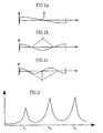
- the figures 1a-1c show the vibration for some natural modes with axial vibration for a free vibrating object. The vertical axes indicate motion to left by positive values and motion to right with negative values. Nods are zero points in an oscillation and maximums are called bellies or antinods.
- Fig. 1a shows the natural mode whose resonance frequency is called the fundamental tone
- fig. 1b shows the second natural mode and fig.
- the frequency spectrum in fig. 2 shows resonance frequencies f 1 to f 3 belonging to the natural modes shown in fig. 1a-1c.
- the axial vibration implies expansion and compression of the body.
- the centrum of the body does not move in the first mode.
- two nods are obtained where the body does not move and so on.
- other mods such as flexural and torsional mods occur and can be used.
- the resonance frequencies are settled by the geometry of the object, density and elastic characteristics such as coefficient of elasticity E and modulus of shearing G.
- the boundary conditions are very important for evaluation of the dynamic characteristics of the object.
- Well-defined reserve conditions are obtained in laboratory environment, typically by hanging up the object in flexible springs, which simulate a free vibrating condition, so-called free-free suspension.
- the arrangement can be considered as a free-free suspension, if the vibrating mass of the springs is small in relationship to the mass of the object and if the fundamental resonance frequency of the system of object-spring is substantially lower than the object's lowest resonance frequency.
- Other types of boundary conditions are free disposition and fixed clamping. The latter apply for a beam in US 5,060,516.
- the invention is primarily intended for sorting objects in classes for which specific demands on strength ⁇ break and/or coefficient of elasticity E are made.
- an application example of the invention for alternative axial vibration of wood is given, but of course, the principle may be applied on other material and other vibrations.
- the primary parameter for strength sorting of wood is bending strength.
- the criteria for an approved sorting (on safe side) is that maximum of 5 of 100 wood pieces may have a bending strength below a value established for each class. Thereby, predicting the bending strength of the timber is the most important criterion at comparisons between different machine operations is apparent that ability. With a good correlation (r 2 ) between the output of the machine and the bending strength of the timber, higher share of timber in the higher sorting classes are obtained.
- the method according to invention is primarily carried out by in length direction exposing the wood to be classified for a physical impact, which sets the wood in an axial vibration.
- the resonance frequencies for two or more natural modes are then detected with a sensor.
- Corresponding elasticity modules are calculated according to equation (i) with knowledge of the density and length of the wood. Thereby, the wood is assumed to rest on supporting means, which simulates a floating condition.
- the sorting method is based on axial vibration, for instance because the boundary conditions are simpler to control for this mode form.
- E dyn The mean value for coefficient of elasticities from the natural modes that are analyzed, E dyn , constitutes the primary parameter for predication of bending strength. This mean value formation implies that more representative rate of the global coefficient of elasticity of the wood is obtained compared to usage of the first natural mode.
- the rigidity of the middle part is entirely critical in the latter case while one in the last case considers the impact of a considerable larger part of the wood.
- the difference between the coefficient of elasticity from different natural modes is a measure on the degree of inhomogeneity of the wood and can be part of an independent parameter for an improved predication of the strength.
- low strength wood is more inhomogeneous than high strength wood.
- the information on an object's degree of inhomogeneity may be of importance for other processes than strength sorting.
- the density can be measured by registering length, width, thickness and weight or by exploiting established contactless technics such as x-ray or microwaves.
- the length and, in applicable cases, also the thickness and width can be decided with commercially an available laser-based technique.
- Figs. 3 and 4 show a first simplified embodiment of an assembly 10, for example in a sawmill, for transportation of the object, in this case timber 11, which is to be classified at a measuring zone for nondestructive classification of the timber.
- nondestructive is meant a testing operation that does not influence the characteristics of the object.
- the assembly 10 for instance includes a number of rails 12 on which endless transport chains 13 are provided having carriers 14.
- Driving means in form of driving assembly 15 and driving wheel 16 are provided to convey the timber 11 to and past a testing unit 18.
- the timber 11 is cross conveyed by means of the conveyor chains 13 with the carriers 14 driving the timber forward continuously.
- the timber 11 normally rests directly on the chain 13 or slide on the rails 11, for example made of steel sections, in which the chains run, so-called chain supports.
- the testing unit 18 When passing by the testing unit 18, the timber is given a physical impact in its length direction by means of a device that is shown in detail in fig. 5. At the impact moment a free vibration condition in respect of the axial vibration is simulated. This is achieved by the timber being brought to rest vertically on a support 20, whose rigidity with regard to the vibrations in longitudinal direction of the timber is low enough and whose co-vibrating mass is low enough.
- the timber 11 can for instance be moved forward resting on the support members, including the conveyer 35 of rubber instead of chains or chain supports, e.g., shown in fig. 4.
- These conveyers 35 have plane regions 20, levels of which are sufficiently higher than the level of the chains/chain supports, so that vertical bearing is only provided on the conveyer 35. However, the level of this plane region 20 is not so high that the carriers 14 loose contact with the timber.
- the support members are mounted slightly inclined so that the timber is gradually raised from the chains/chain supports.
- the conveyer can also be provided with inclined slide bars.
- the rubber band runs in a loop having wheels 17 in both ends of the conveyer.
- the rubber band 35 on which the timber rests slides on a surface with very low friction.
- the friction between the timber 11 and the rubber band 35 is much higher than between the rubber band and underlying slide surface.
- the rubber band is brought to run along the surface. Consequently, the timber does not slide on the rubber band.
- the surface on which the band run has edges so that the band cannot move laterally more than a few millimeters.
- the timber is loaded in its longitudinal direction by the impact mechanism without the rubber band sliding laterally on the smooth track surface.
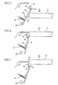
- the testing unit 18, according to figs. 5 - 7 includes an arm 19, which can swing in the vertical plane about an axis 39.
- the arm 19 rotated anticlockwise and a spring 21 is stretched in a corresponding degree.
- the spring 21 is stretched to maximum.
- a slide spacer or wheel 23 attached to the arm presses against the end of the timber 22.
- the timber is moved further forward so that the arm 19 loses contact with the end of the timber 22.
- the arm is turned back toward its rest position by action of the spring force, according to fig. 7.
- the end of the timber 22 is encountered by a stroking body 24, attached to the arm 19 via a bar 25.
- This bar 25 has so low bending strength with regard to the bending in the plane that the bar 25 and its stroking body 24 has a fundamental resonance frequency smaller than a tenth of the lowest resonance frequency of the sample object at axial vibration.
- the bar 25 and its stroking body 24 do not generate acoustic pressure with frequency components that can disturb the measurements.
- a receiving member 26 is positioned so that the arm at impact does not bear on it. Consequently, at the impact, the spring 21 presses the stroking body 24 against the end of the timber 22 so that the bar 25 is bend deformed.
- the high flexibility of the bar 25 results in that the power impulse from the timber piece at the impact is isolated from the arm 19. Thereby, no troubling acoustic pressure is originated from the vibrations in the arm 19 since the arm does not excite in a considerable extent.
- a contactless microphone 27 is arranged for recording the emerged sound waves in the timber 11.
- the microphone 27 is so provided that it, at the impact moment, is essentially in the middle of the width of the timber piece.
- the microphone 27 is placed so that it at the impact moment can collect the radiated acoustic pressure from the end of the timber, originating from the resonance vibrations generated by the impact.
- An alternative embodiment is to detect the vibration of the object with laser-based sensors.
- a number of microphones can be arranged in series, if the width of the timber varies, whereby the recording from the most correctly positioned microphone can be used.
- the microphone is connected to a computer unit (not shown), function of which is described later.
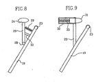
- a more stiff bar 25 via a joint 28 is fastened to the arm 19 and a tension spring 29 provides for the flexibility.
- the tension spring 29 is biased slightly towards a receiving member 30 to ensure same initial position for the stroking body 24 at each attempt.
- Yet another embodiment is shown in fig. 9.
- the cylindrical stroking body 31 is arranged running in a tube 32 with an isolating pressure spring 33 at the bottom.
- the tube is rigidly attached to the arm 19 via a bar 34.
- the mass of the stroking body as well as its geometry and modulus of elasticity with its stop face is in addition fitted to the spring rigidity and dimension of the arm and the bar so that the physical impacts generate/excite vibrations having a frequency content that covers the resonance frequencies to be detected.
- Another method to avoid exciting of the arm is to design the receiving member so that impacts are damped.
- the assemblies for example according to figs. 3 or 4, are assumed to be located in a sawmill or other wood refining industry as part of the process where the timber is cross conveyed, for instance in so-called trimmer.
- a timber piece with varying length of about 2-5 m can be classified in the ongoing process during a time period of just one to two seconds.
- the frequency contents in the impacts are such that the first two axial vibration modes can be excited for all timber pieces intended to be sorted.
- the reflected sound from the end of the timber, recorded by the microphone 27 contains same frequency content as the impacts gave raise to.
- the frequencies that coincide with the two-lowest axial resonance frequencies of the timber piece will exhibit strong increased acoustic pressure levels in relation to the remaining frequencies. Also, adjacent frequencies will exhibit high amplitudes.
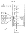
- Fig. 10 schematically shows a block diagram for a computer unit, which partly can control the assembly and partly processes the sound received from the microphone.
- the sound recorded by the microphone 27 is amplified in an amplifier 101 and the analog response signal in a time unit is analogue to the converted 102 and Fourier transformed 103 digitalized "signal" in the frequency plane, whereby an acoustic pressure spectrum 104 is created.
- the resonance frequencies in this spectrum can then simply be decided by means of an algorithm scanning 105 the spectrum after corresponding high amplitude values.
- the values are compared to reasonable values for actual length, which is found stored in a database 106 by the computer unit 100, which manages the measurement and calculation procedure.
- a mean value 107 for the estimated coefficient of elasticity E dyn according to equation (i) is calculated.
- the classifying value and/or the interval is simply changed in the computer unit 100, which can operate as a control unit of the sorting machine.
- the timber piece is marked for ocular inspection and control 109.
- the machine also generates information for guiding each individual timber piece to right "line” in a later working moment.
- the information about mass density and timber length are fetched from the computer unit 100.
- the timber length can be determined by means of known commercial laser techniques 110 in close connection to the resonance frequency measurement.
- the timber piece density can be decided according to one of two alternatives. In the first one, wave technique 111 and laser-based length measurement 112 are used, whereby the mass M and further geometrical dimensions, cross section dimensions T, B are obtained.
- the density ⁇ can also be decided by means of microwave technology. Also, this technique gives information about the moisture ratio, which is a significant parameter for coefficient of elasticity. The moisture ratio may otherwise be assigned an assumed value based on the climatic conditions at proceeding storage.
- the length L and the cross section dimension B and T are intended to be measured by means of laser technique, which today is used in several sawmills. The measured data from such a commercial equipment is transmitted to the computer unit of the sorting machine. Timber length L is obtained by means of laser-based length measuring technique.
- the marking is carried out ocularly readable to be used and controlled in later product stages.
- the assembly can leave information about the sorting result to the control unit to enable physical separate storing of the timber in different strength classes after each timber unit leaving the sorting machine.
- Data storage should partly satisfy the different demands as a basis for statistics and partly satisfy the demands directed by the certifying authorities in connection with a reliability control and calibration etc.
- the method can be applied on objects of wood of any length and cross-section.
- the length can preferably be at least 4 times larger than cross-section dimensions.
- the object can be logs of wood, poles, or blocks such as boards, boarding, glulam beams and laminated wood beams.
- the method can also be applied to I-beams with a rib and flanges of wood or wood-based material.
- piezoelectric sensors can be used to.
- the method and the device according to the present invention can in principle be applied to any rigid, preferably prismatic object on which theory of elasticity can be apply, such as brick blocks, concrete panels, cement stabilized haydite elements, elements of steel, plastic, gypsum etc., with a view to determine some of the parameters, such as coefficient of elasticity, dimension or density.
- the timber has longitudinal, frequently throughout, cracks which originate from timber drying. These cracks, which frequently appear at the ends reduce the capacity to hold against lateral forces on the timber. One can simply say that the shear strength of the timber is low. Existence of these kinds of cracks is consequently important for strength sorting. Presently, these cracks are estimated visually by educated sorters since no machine is yet found for reliable detection.
- one with the present method can decide the density of the object in weightless state provided that the coefficient of elasticity, geometry and resonance frequency are known.
- geometrical dimensions for different objects can be decided through the method according to the present invention.
Landscapes
- Life Sciences & Earth Sciences (AREA)
- Physics & Mathematics (AREA)
- General Physics & Mathematics (AREA)
- Chemical & Material Sciences (AREA)
- Health & Medical Sciences (AREA)
- Pathology (AREA)
- Analytical Chemistry (AREA)
- Biochemistry (AREA)
- General Health & Medical Sciences (AREA)
- Immunology (AREA)
- Engineering & Computer Science (AREA)
- Acoustics & Sound (AREA)
- Wood Science & Technology (AREA)
- Food Science & Technology (AREA)
- Medicinal Chemistry (AREA)
- Investigating Or Analyzing Materials By The Use Of Ultrasonic Waves (AREA)
- Length Measuring Devices Characterised By Use Of Acoustic Means (AREA)
- Analysing Materials By The Use Of Radiation (AREA)
- Two-Way Televisions, Distribution Of Moving Picture Or The Like (AREA)
Claims (25)
- Ein Verfahren zur zerstörungsfreien Bestimmung von Steifigkeit, Festigkeit, und/oder struktureller Eigenschaften eines vorzugsweise länglichen und/oder tafelförmigen Objekts (11), beziehungsweise Bestimmung der geometrischen Abmessungen des Objekts, einschließlich der folgenden Schritte:das Befördern des Objekts (11) zu einer Prüfeinrichtung (18), deren Vorrichtung (18) einen schwenkbaren Arm (19) mit einem Schlagkörper (24,31) enthält;das Betätigen des vorgenannten Arms (19) durch die Förderbewegung des besagten Objekts (11), um das Objekt (11) mit dem besagten Schlagkörper (24, 31) zu beaufschlagen;das Versetzen des Objekts (11) in freie Vibration mit mindestens einer Eigenresonanzfrequenzschwingung desselben durch dieses Vorgehen;das Feststellen der Vibration des Objektes (11), die durch die besagte Beaufschlagung hervorgerufen worden ist; unddas Feststellen einer Eigenschaft des Objekts (11) aus der besagten Vibrationsschwingung.
- Das Verfahren nach Anspruch 1,
dadurch gekennzeichnet, dass die Eigenschwingungen axiale und/oder Biegeschwingungen beinhalten. - Das Verfahren nach Anspruch 1 oder 2,
dadurch gekennzeichnet, dass das Modul der Schubmodul aus der Torsionsschwingung zur Charakterisierung des Objektes benutzt wird. - Das Verfahren nach Anspruch 1,
dadurch gekennzeichnet, dass Resonanzfrequenzen (fn,exp), welche zu der Eigenschwingung mit der Schwingungsnummer n gehören, gemessen werden, und dass die gemessenen Resonanzfrequenzen mit nachen theoretischen Werten (fn,theo) verglichen werden. - das Verfahren nach Anspruch 4,
dadurch gekennzeichnet, dass durch den Vergleich der gemessenen Werte mit den theoretischen Werten eine Überbestimmung durchgeführt wird, welche als Basis zur Bestimmung der Werte für Steifigkeit und/oder der damit verbundenen Festigkeit durch Mittelwertbildung benutzt wird. - das Verfahren nach Anspruch 4,
dadurch gekennzeichnet, dass durch den Vergleich der gemessenen Werte mit den theoretischen Werten eine Überbestimmung durchgeführt wird, welche als Basis für die Bestimmung der geometrischen Abweichung der Steifigkeit und/oder der damit verbundenen Festigkeit benutzt wird. - das Verfahren nach Anspruch 4,
dadurch gekennzeichnet, dass durch den Vergleich der gemessenen Werte mit den theoretischen Werten eine Überbestimmung durchgeführt wird, welche als Basis zur Bestimmung der Inhomogenität mittels einer statistischen Streuwertverteilung in Verbindung mit der Mittelwertbildung benutzt wird. - das Verfahren nach Anspruch 4,
dadurch gekennzeichnet, dass durch den Vergleich der gemessenen Werte mit den theoretischen Werten eine Überbestimmung durchgeführt wird, welche als Basis zum Ausschließen fehlerhafter Messergebnisse bei einer unrealistisch breiten statistischen Streuverteilung einer festgestellten Steifigkeit, welche aus verschiedenen Resonanzfrequenzen (fn) bestimmt worden ist, benutzt wird. - das Verfahren nach Anspruch 1,
dadurch gekennzeichnet, dass die Reaktion des Objektes in Form von Vibrationen mit Hilfe mindestens eines Prüfgeräts (27) aufgezeichnet wird, und dass die Resonanzfrequenzen durch Datenverarbeitung in einem Rechenwerk (100) bestimmt werden. - das Verfahren nach Anspruch 1,
dadurch gekennzeichnet, dass die Bewegung, die Form, die Masse und die Steifigkeit des Schlagkörpers (24, 31) so bestimmt werden,
dass eine geeignete physikalische Beaufschlagung des Objekts in Bezug auf Frequenz und Energiegehalt erzielt wird. - das Verfahren, nach einem der Ansprüche 9 oder 10,
dadurch gekennzeichnet, dass die Bewegungsenergie des Objekts zum Erzeugen der physikalischen Beaufschlagung benutzt wird, oder das Objekt durch seine Bewegung eine Feder (21) in Spannung versetzt, welche die besagte physikalische Beaufschlagung hervorruft, - das Verfahren nach einem der Ansprüche 9-11,
dadurch gekennzeichnet, dass das Objekt (11) zum Zeitpunkt der Einwirkung auf einer Einrichtung (20) ruht, welche ideale Grenzbedingungen für Eigenschwingungen simuliert, die analysiert werden. - das Verfahren nach einem der Ansprüche 9-12,
dadurch gekennzeichnet, dass die Resonanzfrequenzen durch automatisches Abtasten des Frequenzspektrums mittels Fouriertransformation der Ansprechreaktion des Objektes auf Vibrationen und/oder auf Schalldruck, bestimmt werden. - das Verfahren nach Anspruch 1,
dadurch gekennzeichnet, dass das Objekt (11) ein im wesentlichen frei schwingendes, längliches Objekt ist, und die Resonanzfrequenzen fA-n für unterschiedliche Eigenschwingungen n berechnet werden durch:- fA-n
- =Resonanzfrequenz für axiale Schwingung mit der Nummer n (Hz)
- n
- =Schwingungsnummer (-)
- L
- =Länge (m)
- E
- =Elastizitätsmodul (N/m2)
- ρ
- =Dichte (kg/m3) ist.
- das Verfahren nach Anspruch 1,
dadurch gekennzeichnet, dass bei Biege- und Torsionsschwingungen der Elastizitätsmodul für unterschiedliche
Eigenschwingungen des Objektes sich folgendermaßen ergibt:- EA-n
- Elastizitätsmodul (N/m2) für die Schwingung mit der Nummer n,
- fA-n
- Resonanzfrequenz für die axiale Schwingung mit der Nummer n (Hz),
- n
- Schwingungsnummer
- L
- Länge (m)
- ρ
- Dichte (kg/m2).
- eine Vorrichtung zur zerstörungsfreien Bestimmung der Steifigkeit, der Festigkeit und/oder struktureller Eigenschaften eines vorzugsweise länglichen und/oder tafelförmigen Objektes (11), beziehungsweise Bestimmung der geometrischen Abmessungen des Objektes durch Stoßerregung und
Erfassung der Resonanzfrequenz einer Eigenschwingung, bestehend aus: einer Transporteinrichtung (10,12,13,14), welche so angeordnet ist, dass sie das Objekt (11) während der Bewegung trägt,
einer Einrichtung (27), die so angeordnet ist, dass sie die Schwingungen der Resonanzen des Objekts (11) aufzeichnet,
einer Einrichtung (100), die für das Verarbeiten der aufgezeichneten Vibrationsschwingungen zuständig ist;
dadurch gekennzeichnet, dass
besagte Vorrichtung eine Prüfvorrichtung (18) enthält, welche einen schwenkbaren Arm (19) mit einem Schlagkörper (24, 31) enthält und besagte Transporteinrichtung (10, 12, 13, 14) zur Bewegung des Objektes (11) so angeordnet ist, dass sie besagten Arm (19) betätigt, um das Objekt (11) mit besagtem Schlagkörper (24, 31) zu beaufschlagen;
dabei das Objekt (11) veranlasst wird, bei mindestens einer Eigenresonanzfrequenzschwingung desselben frei zu schwingen. - Die Vorrichtung nach Anspruch 16,
dadurch gekennzeichnet, dass die Prüfeinrichtung (18) einen einen schwenkbaren Arm (19) mit einem Schlagkörper (24, 31) enthält, welcher durch das Auslösen einer Feder (21, 29, 33) eine physikalische Beaufschlagung auf das Objekt verursacht. - Die Vorrichtung nach Anspruch 16,
dadurch gekennzeichnet, dass Einrichtungen (20) angeordnet sind, auf welchen das Objekt (11) zum Zeitpunkt der Beaufschlagung ruht, um freie Schwingungsbedingungen des Objektes zu simulieren. - Die Vorrichtung nach Anspruch 16,
dadurch gekennzeichnet, dass die Prüfeinrichtung (27) aus mindestens einem Mikrofon und/oder Laser, sowie Sensoren und/oder einem piezoelektrischen Sensor besteht. - Die Vorrichtung nach Anspruch 16,
dadurch gekennzeichnet, dass die Prüfeinrichtung berührungslos misst. - Die Vorrichtung nach Anspruch 16,
gekennzeichnet dadurch, dass die Recheneinheit (100) Mittel zur Erfassung analoger Daten, einen Analog-/Digitalwandler (102) zur Umwandlung analoger Daten in digitale Daten, eine Einrichtung zur Fouriertransformation der Daten (103), eine Verarbeitungseinheit (104) zum Erzeugen eines Frequenzspektrums, eine Verarbeitungseinheit zum Vergleich, zur Berechnung und Prüfung (105; 107; 108) und eine Speichereinrichtung zum Verarbeiten der
Anweisungen, sowie einen Speicher (106) zum Speichern der Daten beinhaltet. - Die Vorrichtung nach einem der Ansprüche 16-21,
dadurch gekennzeichnet, dass die Prüfeinrichtung (18) aus einem Schlagabsorptionskörper (38) besteht, auf welchem das Objekt (11) mittels eines Schlagwerks (37) verschoben wird, - Eine Baugruppe, welche eine Vorrichtung nach einem der Ansprüche 16-21 enthält,
dadurch gekennzeichnet, dass sie darüber hinaus Fördermittel (13, 35, 36) zum Transport des Objekts (11) zur Prüfeinrichtung (18), eine Einrichtung (15) zum Betreiben der Fördermittel, sowie mögliche Markier- oder Sortiereinrichtungen enthält. - Eine Baugruppe nach Anspruch 23,
dadurch gekennzeichnet, dass die Fördermittel aus einem Förderband (35), welches eine rauhe gummiartige Oberfläche oder Transportketten (13) mit Transportbehältern (14) besitzt, bestehen. - Eine Baugruppe nach Anspruch 23,
dadurch gekennzeichnet, dass ein Trägerelement (20) aus einem Band mit gummiartiger Oberfläche besteht, und in Führungsschienen angeordnet ist, in denen das Band mit geringer Reibung gleitet, dass das Band infolge hoher Reibung zwischen dem Band und dem Objekt beschleunigt, wenn das Objekt die Fördereinrichtung berührt, so dass das Objekt zum Messzeitpunkt ohne relative Bewegung auf dem Band ruht.
Applications Claiming Priority (3)
| Application Number | Priority Date | Filing Date | Title |
|---|---|---|---|
| SE9602374 | 1996-06-17 | ||
| SE9602374A SE511602C2 (sv) | 1996-06-17 | 1996-06-17 | Förfarande jämte anordning för oförstörande klassificering av företrädesvis långsträckta och/eller skivformade objekt |
| PCT/SE1997/001090 WO1998001737A1 (en) | 1996-06-17 | 1997-06-17 | Method and arrangement for nondestructive classification |
Publications (2)
| Publication Number | Publication Date |
|---|---|
| EP0906560A1 EP0906560A1 (de) | 1999-04-07 |
| EP0906560B1 true EP0906560B1 (de) | 2005-08-31 |
Family
ID=20403025
Family Applications (1)
| Application Number | Title | Priority Date | Filing Date |
|---|---|---|---|
| EP97928616A Expired - Lifetime EP0906560B1 (de) | 1996-06-17 | 1997-06-17 | Verfahren und vorrichtung zur zerstörungsfreien klassifikation |
Country Status (10)
| Country | Link |
|---|---|
| US (1) | US6347542B1 (de) |
| EP (1) | EP0906560B1 (de) |
| JP (1) | JP4074664B2 (de) |
| AT (1) | ATE303588T1 (de) |
| AU (1) | AU720772B2 (de) |
| CA (1) | CA2258514C (de) |
| DE (1) | DE69734106T2 (de) |
| NZ (1) | NZ333450A (de) |
| SE (1) | SE511602C2 (de) |
| WO (1) | WO1998001737A1 (de) |
Cited By (1)
| Publication number | Priority date | Publication date | Assignee | Title |
|---|---|---|---|---|
| WO2020126026A1 (de) | 2018-12-21 | 2020-06-25 | Tmd Friction Services Gmbh | Vorrichtung und verfahren zur ermittlung mechanischer eigenschaften eines prüfkörpers |
Families Citing this family (35)
| Publication number | Priority date | Publication date | Assignee | Title |
|---|---|---|---|---|
| US6026689A (en) * | 1998-02-25 | 2000-02-22 | Weyerhaeuser Company | Log cutting optimization system |
| US6769306B2 (en) | 1998-12-17 | 2004-08-03 | Carter Holt Harvey Limited | Log cutting procedures |
| NZ333434A (en) * | 1998-12-17 | 1999-10-28 | Carter Holt Harvey Ltd | Determining log length by passing ultrasonic signal through log, and using length information to determining cut positions |
| ES2209911T3 (es) * | 1999-05-11 | 2004-07-01 | Frank Rinn | Dispositivo para el examen de materiales. |
| EP1208375A4 (de) * | 1999-07-30 | 2007-04-18 | Fibre Gen Instr Ltd | Vorrichtung zur überprüfung von baumstämmen |
| NZ503953A (en) * | 2000-04-12 | 2002-12-20 | Carter Holt Harvey Ltd | Apparatus and method for estimating timber stiffness profiles of a log by determining the density profile of a cant |
| NZ505896A (en) * | 2000-07-21 | 2003-05-30 | Ind Res Ltd | Method and apparatus for assessing or predicting characteristics of wood or other materials by varying frequency of acoustic transmitter and sensing a response |
| US6507798B1 (en) * | 2000-10-12 | 2003-01-14 | The United States Of America As Represented By The Secretary Of The Navy | Time-frequency dependent damping via Hilbert damping spectrum |
| FR2820204B1 (fr) * | 2001-01-29 | 2005-02-25 | Casagrande Stephanie Delph Bos | Procede d'evaluation et de controle non destructif de la qualite de panneaux |
| CA2436492A1 (en) * | 2001-01-31 | 2002-08-08 | Board Of Control Of Michigan Technological University | System for and method of performing evaluation techniques on a log or round timber |
| TW509782B (en) * | 2001-11-20 | 2002-11-11 | Taiwan Forestry Res Inst | Nondestructive testing technique for wood stress wave |
| TWI225152B (en) * | 2003-01-29 | 2004-12-11 | Taiwan Forestry Res Inst | Method for non-destructive stress wave testing of wood |
| US20040173031A1 (en) * | 2003-03-06 | 2004-09-09 | Shlomo Gicza | Mass flow measurement |
| GB2403338B (en) * | 2003-06-24 | 2005-11-23 | Aicom Ltd | Resonance and/or vibration measurement device |
| US7066007B2 (en) * | 2003-10-17 | 2006-06-27 | Eyerhaeuser Company | Systems and methods for predicting the bending stiffness of wood products |
| US6990436B1 (en) * | 2003-11-28 | 2006-01-24 | The United States Of America As Represented By The Administrator Of The National Aeronautics And Space Administration | Computing frequency by using generalized zero-crossing applied to intrinsic mode functions |
| WO2005104258A1 (ja) * | 2004-04-27 | 2005-11-03 | Ngk Insulators, Ltd. | 弾性体の検査方法、検査装置、及び寸法予測プログラム |
| NZ536818A (en) * | 2004-11-24 | 2007-05-31 | Carter Holt Harvey Ltd | Tree stem or log appraising apparatus |
| WO2007011296A1 (en) * | 2005-07-15 | 2007-01-25 | A-Sort Ab | Means and method for classifying logs |
| US7430914B2 (en) * | 2005-09-16 | 2008-10-07 | Mitsui Babcock (Us) Llc | Vibration analyzing device |
| US7676953B2 (en) * | 2006-12-29 | 2010-03-16 | Signature Control Systems, Inc. | Calibration and metering methods for wood kiln moisture measurement |
| US20080295602A1 (en) * | 2007-06-01 | 2008-12-04 | Gavin Wallace | Method and System for Sorting Green Lumber |
| JP4875589B2 (ja) * | 2007-11-01 | 2012-02-15 | 本田技研工業株式会社 | パネルの検査装置及び検査方法 |
| US8566041B2 (en) * | 2009-08-20 | 2013-10-22 | United States Gypsum Company | Method for determining structural parameters of composite building panels |
| US8204698B2 (en) * | 2009-08-20 | 2012-06-19 | United States Gypsum Company | Method for determining structural parameters of composite building panels |
| IT1398908B1 (it) * | 2010-03-03 | 2013-03-21 | Microtec Srl | Metodo ed apparecchiatura per la determinazione della frequenza propria di tavole di legno |
| US9068902B2 (en) * | 2011-05-13 | 2015-06-30 | Fisher Controls International Llc | Methods and apparatus for evaluating vibration resistance of a component of a fluid control valve |
| EP2914959B1 (de) * | 2012-11-01 | 2018-06-27 | Rise Research Institutes Of Sweden Ab | Verfahren und system zur automatischen bestimmung einer baumstammqualität in gefrorenem oder ungefrorenem zustand |
| US9134212B2 (en) * | 2013-07-08 | 2015-09-15 | The Boeing Company | Modal impact testing assembly, system and method |
| US9383341B2 (en) * | 2013-10-29 | 2016-07-05 | Metriguard Inc. | Sonic lumber tester |
| EP3914894A1 (de) * | 2019-01-25 | 2021-12-01 | Brookhuis Applied Technologies B.V. | Automatisierte einstufung von länglichen holzgegenständen |
| CN109682458B (zh) * | 2019-03-05 | 2024-05-10 | 重庆克来智能科技有限公司 | 一种检测机床及其用于检测零件固有频率的装置 |
| EP4111164A1 (de) * | 2020-03-02 | 2023-01-04 | Usnr, Llc | Akustische bewertung von holzeigenschaften |
| EP4227662A1 (de) * | 2022-02-14 | 2023-08-16 | GrindoSonic BV | Verbesserter positioniertisch für aufprallerregungsmessungen |
| FR3136857A1 (fr) * | 2022-06-16 | 2023-12-22 | Safran Ceramics | Procede de mesure du module de rigidite axial d’une eprouvette en materiau composite a matrice ceramique |
Family Cites Families (18)
| Publication number | Priority date | Publication date | Assignee | Title |
|---|---|---|---|---|
| US2102614A (en) | 1935-09-20 | 1937-12-21 | Howard H Couch | Method of producing and distinguishing frequency vibrations |
| US2486984A (en) | 1943-05-07 | 1949-11-01 | Carborundum Co | Vibration apparatus for testing articles |
| CA918286A (en) | 1968-09-13 | 1973-01-02 | Washington State University Research Foundation | Non-destructive method of grading wood materials |
| US4399701A (en) | 1980-06-03 | 1983-08-23 | Unisearch Limited | Method and means for detecting decay in wood |
| US4446733A (en) | 1981-08-17 | 1984-05-08 | Design Professionals Financial Corporation | Stress control in solid materials |
| US4926691A (en) | 1986-03-11 | 1990-05-22 | Powertech Labs, Inc. | Apparatus and method for testing wooden poles |
| US4722223A (en) * | 1986-05-06 | 1988-02-02 | Her Majesty The Queen In Right Of The Province Of Alberta, As Represented By The Minister Of Energy & Natural Resources | Transverse vibration apparatus for grading wood panels |
| GB8622731D0 (en) * | 1986-09-20 | 1986-10-29 | Bio Kil Chemicals Ltd | Testing timbers |
| US4852029A (en) * | 1987-06-17 | 1989-07-25 | Accu-Tech Incorporated | Automated material classification apparatus and method |
| CA1322282C (en) * | 1989-09-29 | 1993-09-21 | Wing-Cheong Lau | Non-destructive method and apparatus for checking the quality of manufactured wood panels |
| US5207100A (en) | 1991-07-25 | 1993-05-04 | The United States Of America As Represented By The Secretary Of The Navy | Method and device for measuring underwater vehicle hull vibration |
| US5255565A (en) | 1991-11-12 | 1993-10-26 | Vibra-Metrics, Inc. | Method and apparatus for monitoring multiple points on a vibrating structure |
| US5533399A (en) * | 1992-09-30 | 1996-07-09 | Wayne State University | Method and apparatus for non-destructive measurement of elastic properties of structural materials |
| EP0599601A3 (de) * | 1992-11-23 | 1995-07-19 | British Aerospace | Schwingplatten Analyse. |
| DE9315506U1 (de) * | 1993-10-13 | 1993-12-02 | Fagus-Grecon Greten Gmbh & Co Kg, 31061 Alfeld | Vorrichtung zur maschinellen Festigkeitssortierung von Schnittholz |
| US5520052A (en) * | 1994-02-10 | 1996-05-28 | The United States Of America As Represented By The United States Department Of Energy | Method and apparatus for determining material structural integrity |
| DE4427692A1 (de) * | 1994-08-04 | 1996-02-08 | Bayerische Motoren Werke Ag | Verfahren zum Bestimmen des Schwingungsverhaltens eines Körpers |
| US5621172A (en) * | 1995-04-03 | 1997-04-15 | State Of Oregon Acting By And Through The State Board Of Higher Education On Behalf Of Oregon State University | Method and apparatus for testing material strengths |
-
1996
- 1996-06-17 SE SE9602374A patent/SE511602C2/sv not_active IP Right Cessation
-
1997
- 1997-06-17 US US09/202,535 patent/US6347542B1/en not_active Expired - Lifetime
- 1997-06-17 AT AT97928616T patent/ATE303588T1/de active
- 1997-06-17 EP EP97928616A patent/EP0906560B1/de not_active Expired - Lifetime
- 1997-06-17 WO PCT/SE1997/001090 patent/WO1998001737A1/en not_active Ceased
- 1997-06-17 JP JP50365198A patent/JP4074664B2/ja not_active Expired - Fee Related
- 1997-06-17 CA CA002258514A patent/CA2258514C/en not_active Expired - Lifetime
- 1997-06-17 DE DE69734106T patent/DE69734106T2/de not_active Expired - Lifetime
- 1997-06-17 NZ NZ333450A patent/NZ333450A/xx not_active IP Right Cessation
- 1997-06-17 AU AU32824/97A patent/AU720772B2/en not_active Ceased
Cited By (1)
| Publication number | Priority date | Publication date | Assignee | Title |
|---|---|---|---|---|
| WO2020126026A1 (de) | 2018-12-21 | 2020-06-25 | Tmd Friction Services Gmbh | Vorrichtung und verfahren zur ermittlung mechanischer eigenschaften eines prüfkörpers |
Also Published As
| Publication number | Publication date |
|---|---|
| CA2258514C (en) | 2005-03-29 |
| JP2002511921A (ja) | 2002-04-16 |
| JP4074664B2 (ja) | 2008-04-09 |
| AU720772B2 (en) | 2000-06-08 |
| NZ333450A (en) | 2002-11-26 |
| SE9602374D0 (sv) | 1996-06-17 |
| SE9602374L (sv) | 1997-12-18 |
| WO1998001737A1 (en) | 1998-01-15 |
| EP0906560A1 (de) | 1999-04-07 |
| AU3282497A (en) | 1998-02-02 |
| DE69734106D1 (de) | 2005-10-06 |
| ATE303588T1 (de) | 2005-09-15 |
| CA2258514A1 (en) | 1998-01-15 |
| US6347542B1 (en) | 2002-02-19 |
| DE69734106T2 (de) | 2006-03-16 |
| SE511602C2 (sv) | 1999-10-25 |
Similar Documents
| Publication | Publication Date | Title |
|---|---|---|
| EP0906560B1 (de) | Verfahren und vorrichtung zur zerstörungsfreien klassifikation | |
| WO1998001737A9 (en) | Method and arrangement for nondestructive classification | |
| US7066007B2 (en) | Systems and methods for predicting the bending stiffness of wood products | |
| EP0403020B1 (de) | Zerstörungsfreie Prüfung von Strukturelementen | |
| EP1228364B1 (de) | System und verfahren zur bestimmung der struktureigenschaften von holzteilen mit hilfe von ultraschall | |
| US4838085A (en) | Methods and appartaus for non-destructing evaluation of the mechanical properties of composite materials | |
| US5307679A (en) | Method and apparatus for evaluating the drying properties of un-dried wood | |
| Divos et al. | Lumber strength estimation by multiple regression | |
| US7043990B2 (en) | System for and method of performing evaluation techniques on a log or round timber | |
| AU2002242023A1 (en) | System for and method of performing evaluation techniques on a log or round timber | |
| AU2006270551A1 (en) | Means and method for classifying logs | |
| US20080295602A1 (en) | Method and System for Sorting Green Lumber | |
| RU2219538C2 (ru) | Способ обнаружения трещин в твердом теле | |
| NZ556744A (en) | Impact method and system for determining the modulus of elasticity in lumber | |
| Biechele et al. | Comparison of NDE techniques for assessing mechanical properties of unjointed and finger-jointed lumber. | |
| NL1018940C1 (nl) | Werkwijze en inrichting voor het onderzoeken van eieren. | |
| Teixeira | Evaluation of maximum strength and modulus of elasticity of Douglas-fir lumber in axial to grain tension by two nondestructive techniques | |
| US20050216226A1 (en) | Method for determining physical properties of wood | |
| Bekher et al. | Applying impact loading for revealing cracks in glass by acoustic emission method | |
| CN117110436B (zh) | 一种胶合木层板强度等级的高速连续在线检测设备及方法 | |
| WO2005078435A1 (en) | Method and system for determining the modulus of elasticity of green lumber | |
| AU2008207613B2 (en) | Tree Stem Or Log Appraising Apparatus | |
| Straže et al. | Analysis of size effect on determination of mechanical properties of Norway spruce wood | |
| Halabe et al. | Nondestructive evaluation of green dimension lumber using stress wave and transverse vibration techniques | |
| RU2251687C1 (ru) | Способ акустического контроля насосных штанг |
Legal Events
| Date | Code | Title | Description |
|---|---|---|---|
| PUAI | Public reference made under article 153(3) epc to a published international application that has entered the european phase |
Free format text: ORIGINAL CODE: 0009012 |
|
| 17P | Request for examination filed |
Effective date: 19990118 |
|
| AK | Designated contracting states |
Kind code of ref document: A1 Designated state(s): AT CH DE DK FI FR GB IE IT LI NL |
|
| 17Q | First examination report despatched |
Effective date: 20030901 |
|
| RAP1 | Party data changed (applicant data changed or rights of an application transferred) |
Owner name: DYNALYSE AB |
|
| GRAP | Despatch of communication of intention to grant a patent |
Free format text: ORIGINAL CODE: EPIDOSNIGR1 |
|
| RIN1 | Information on inventor provided before grant (corrected) |
Inventor name: PERSTORPER, MIKAEL Inventor name: OHLSSON, SVEN Inventor name: LARSSON, DANIEL |
|
| GRAS | Grant fee paid |
Free format text: ORIGINAL CODE: EPIDOSNIGR3 |
|
| GRAA | (expected) grant |
Free format text: ORIGINAL CODE: 0009210 |
|
| RIN1 | Information on inventor provided before grant (corrected) |
Inventor name: PERSTORPER, MIKAEL Inventor name: OHLSSON, SVEN Inventor name: LARSSONS SANDIN, DANIEL |
|
| AK | Designated contracting states |
Kind code of ref document: B1 Designated state(s): AT CH DE DK FI FR GB IE IT LI NL |
|
| PG25 | Lapsed in a contracting state [announced via postgrant information from national office to epo] |
Ref country code: NL Free format text: LAPSE BECAUSE OF FAILURE TO SUBMIT A TRANSLATION OF THE DESCRIPTION OR TO PAY THE FEE WITHIN THE PRESCRIBED TIME-LIMIT Effective date: 20050831 Ref country code: LI Free format text: LAPSE BECAUSE OF FAILURE TO SUBMIT A TRANSLATION OF THE DESCRIPTION OR TO PAY THE FEE WITHIN THE PRESCRIBED TIME-LIMIT Effective date: 20050831 Ref country code: IT Free format text: LAPSE BECAUSE OF FAILURE TO SUBMIT A TRANSLATION OF THE DESCRIPTION OR TO PAY THE FEE WITHIN THE PRESCRIBED TIME-LIMIT;WARNING: LAPSES OF ITALIAN PATENTS WITH EFFECTIVE DATE BEFORE 2007 MAY HAVE OCCURRED AT ANY TIME BEFORE 2007. THE CORRECT EFFECTIVE DATE MAY BE DIFFERENT FROM THE ONE RECORDED. Effective date: 20050831 Ref country code: FI Free format text: LAPSE BECAUSE OF FAILURE TO SUBMIT A TRANSLATION OF THE DESCRIPTION OR TO PAY THE FEE WITHIN THE PRESCRIBED TIME-LIMIT Effective date: 20050831 Ref country code: CH Free format text: LAPSE BECAUSE OF FAILURE TO SUBMIT A TRANSLATION OF THE DESCRIPTION OR TO PAY THE FEE WITHIN THE PRESCRIBED TIME-LIMIT Effective date: 20050831 |
|
| REG | Reference to a national code |
Ref country code: GB Ref legal event code: FG4D Ref country code: CH Ref legal event code: EP |
|
| REG | Reference to a national code |
Ref country code: IE Ref legal event code: FG4D |
|
| REF | Corresponds to: |
Ref document number: 69734106 Country of ref document: DE Date of ref document: 20051006 Kind code of ref document: P |
|
| PG25 | Lapsed in a contracting state [announced via postgrant information from national office to epo] |
Ref country code: DK Free format text: LAPSE BECAUSE OF FAILURE TO SUBMIT A TRANSLATION OF THE DESCRIPTION OR TO PAY THE FEE WITHIN THE PRESCRIBED TIME-LIMIT Effective date: 20051130 |
|
| NLV1 | Nl: lapsed or annulled due to failure to fulfill the requirements of art. 29p and 29m of the patents act | ||
| REG | Reference to a national code |
Ref country code: CH Ref legal event code: PL |
|
| ET | Fr: translation filed | ||
| PG25 | Lapsed in a contracting state [announced via postgrant information from national office to epo] |
Ref country code: IE Free format text: LAPSE BECAUSE OF NON-PAYMENT OF DUE FEES Effective date: 20060619 |
|
| PLBE | No opposition filed within time limit |
Free format text: ORIGINAL CODE: 0009261 |
|
| STAA | Information on the status of an ep patent application or granted ep patent |
Free format text: STATUS: NO OPPOSITION FILED WITHIN TIME LIMIT |
|
| 26N | No opposition filed |
Effective date: 20060601 |
|
| REG | Reference to a national code |
Ref country code: IE Ref legal event code: MM4A |
|
| PGFP | Annual fee paid to national office [announced via postgrant information from national office to epo] |
Ref country code: FR Payment date: 20080619 Year of fee payment: 12 |
|
| REG | Reference to a national code |
Ref country code: FR Ref legal event code: ST Effective date: 20100226 |
|
| PG25 | Lapsed in a contracting state [announced via postgrant information from national office to epo] |
Ref country code: FR Free format text: LAPSE BECAUSE OF NON-PAYMENT OF DUE FEES Effective date: 20090630 |
|
| REG | Reference to a national code |
Ref country code: FR Ref legal event code: RN |
|
| REG | Reference to a national code |
Ref country code: FR Ref legal event code: IC Effective date: 20111128 |
|
| PGFP | Annual fee paid to national office [announced via postgrant information from national office to epo] |
Ref country code: AT Payment date: 20120626 Year of fee payment: 16 |
|
| PGFP | Annual fee paid to national office [announced via postgrant information from national office to epo] |
Ref country code: GB Payment date: 20130626 Year of fee payment: 17 Ref country code: DE Payment date: 20130627 Year of fee payment: 17 |
|
| REG | Reference to a national code |
Ref country code: DE Ref legal event code: R119 Ref document number: 69734106 Country of ref document: DE |
|
| REG | Reference to a national code |
Ref country code: AT Ref legal event code: MM01 Ref document number: 303588 Country of ref document: AT Kind code of ref document: T Effective date: 20140617 |
|
| GBPC | Gb: european patent ceased through non-payment of renewal fee |
Effective date: 20140617 |
|
| PG25 | Lapsed in a contracting state [announced via postgrant information from national office to epo] |
Ref country code: DE Free format text: LAPSE BECAUSE OF NON-PAYMENT OF DUE FEES Effective date: 20150101 |
|
| REG | Reference to a national code |
Ref country code: DE Ref legal event code: R119 Ref document number: 69734106 Country of ref document: DE Effective date: 20150101 |
|
| PG25 | Lapsed in a contracting state [announced via postgrant information from national office to epo] |
Ref country code: AT Free format text: LAPSE BECAUSE OF NON-PAYMENT OF DUE FEES Effective date: 20140617 Ref country code: GB Free format text: LAPSE BECAUSE OF NON-PAYMENT OF DUE FEES Effective date: 20140617 |