EP4227662A1 - Verbesserter positioniertisch für aufprallerregungsmessungen - Google Patents
Verbesserter positioniertisch für aufprallerregungsmessungen Download PDFInfo
- Publication number
- EP4227662A1 EP4227662A1 EP22156669.8A EP22156669A EP4227662A1 EP 4227662 A1 EP4227662 A1 EP 4227662A1 EP 22156669 A EP22156669 A EP 22156669A EP 4227662 A1 EP4227662 A1 EP 4227662A1
- Authority
- EP
- European Patent Office
- Prior art keywords
- piece
- holder
- solid piece
- impact
- solid
- Prior art date
- Legal status (The legal status is an assumption and is not a legal conclusion. Google has not performed a legal analysis and makes no representation as to the accuracy of the status listed.)
- Withdrawn
Links
- 238000005259 measurement Methods 0.000 title claims abstract description 41
- 230000005284 excitation Effects 0.000 title claims abstract description 15
- 239000007787 solid Substances 0.000 claims abstract description 100
- 230000004044 response Effects 0.000 claims abstract description 52
- 238000012546 transfer Methods 0.000 claims abstract description 7
- 238000013016 damping Methods 0.000 claims description 26
- 238000012360 testing method Methods 0.000 claims description 24
- 238000004458 analytical method Methods 0.000 claims description 8
- 238000000691 measurement method Methods 0.000 claims description 8
- 238000012545 processing Methods 0.000 claims description 8
- 238000000034 method Methods 0.000 description 34
- 230000008569 process Effects 0.000 description 12
- 239000000463 material Substances 0.000 description 11
- 230000010355 oscillation Effects 0.000 description 8
- 238000010146 3D printing Methods 0.000 description 7
- 238000004519 manufacturing process Methods 0.000 description 7
- 230000007547 defect Effects 0.000 description 5
- 230000001419 dependent effect Effects 0.000 description 5
- 238000010603 microCT Methods 0.000 description 5
- 238000012544 monitoring process Methods 0.000 description 5
- 239000000654 additive Substances 0.000 description 4
- 230000000996 additive effect Effects 0.000 description 4
- 238000001228 spectrum Methods 0.000 description 4
- 230000008901 benefit Effects 0.000 description 3
- 239000011343 solid material Substances 0.000 description 3
- 230000001066 destructive effect Effects 0.000 description 2
- 238000001514 detection method Methods 0.000 description 2
- 238000011156 evaluation Methods 0.000 description 2
- 238000010438 heat treatment Methods 0.000 description 2
- 238000011065 in-situ storage Methods 0.000 description 2
- 230000007246 mechanism Effects 0.000 description 2
- 229910052751 metal Inorganic materials 0.000 description 2
- 239000002184 metal Substances 0.000 description 2
- 238000003908 quality control method Methods 0.000 description 2
- 230000003595 spectral effect Effects 0.000 description 2
- 230000002123 temporal effect Effects 0.000 description 2
- FGUUSXIOTUKUDN-IBGZPJMESA-N C1(=CC=CC=C1)N1C2=C(NC([C@H](C1)NC=1OC(=NN=1)C1=CC=CC=C1)=O)C=CC=C2 Chemical compound C1(=CC=CC=C1)N1C2=C(NC([C@H](C1)NC=1OC(=NN=1)C1=CC=CC=C1)=O)C=CC=C2 FGUUSXIOTUKUDN-IBGZPJMESA-N 0.000 description 1
- 230000005534 acoustic noise Effects 0.000 description 1
- 229910045601 alloy Inorganic materials 0.000 description 1
- 239000000956 alloy Substances 0.000 description 1
- 238000010420 art technique Methods 0.000 description 1
- 230000015572 biosynthetic process Effects 0.000 description 1
- 239000000919 ceramic Substances 0.000 description 1
- 238000010276 construction Methods 0.000 description 1
- 230000008021 deposition Effects 0.000 description 1
- 238000006073 displacement reaction Methods 0.000 description 1
- 238000002592 echocardiography Methods 0.000 description 1
- 239000013013 elastic material Substances 0.000 description 1
- 238000005516 engineering process Methods 0.000 description 1
- 239000006260 foam Substances 0.000 description 1
- 238000010978 in-process monitoring Methods 0.000 description 1
- 238000009776 industrial production Methods 0.000 description 1
- 238000007689 inspection Methods 0.000 description 1
- 239000007788 liquid Substances 0.000 description 1
- 230000007774 longterm Effects 0.000 description 1
- 150000002739 metals Chemical class 0.000 description 1
- 238000009659 non-destructive testing Methods 0.000 description 1
- 229920000642 polymer Polymers 0.000 description 1
- 239000000843 powder Substances 0.000 description 1
- 238000007639 printing Methods 0.000 description 1
- 238000001303 quality assessment method Methods 0.000 description 1
- 230000008439 repair process Effects 0.000 description 1
- 230000035945 sensitivity Effects 0.000 description 1
- 238000003325 tomography Methods 0.000 description 1
Images

Classifications
-
- G—PHYSICS
- G01—MEASURING; TESTING
- G01M—TESTING STATIC OR DYNAMIC BALANCE OF MACHINES OR STRUCTURES; TESTING OF STRUCTURES OR APPARATUS, NOT OTHERWISE PROVIDED FOR
- G01M7/00—Vibration-testing of structures; Shock-testing of structures
- G01M7/08—Shock-testing
-
- B—PERFORMING OPERATIONS; TRANSPORTING
- B33—ADDITIVE MANUFACTURING TECHNOLOGY
- B33Y—ADDITIVE MANUFACTURING, i.e. MANUFACTURING OF THREE-DIMENSIONAL [3-D] OBJECTS BY ADDITIVE DEPOSITION, ADDITIVE AGGLOMERATION OR ADDITIVE LAYERING, e.g. BY 3-D PRINTING, STEREOLITHOGRAPHY OR SELECTIVE LASER SINTERING
- B33Y80/00—Products made by additive manufacturing
-
- G—PHYSICS
- G01—MEASURING; TESTING
- G01M—TESTING STATIC OR DYNAMIC BALANCE OF MACHINES OR STRUCTURES; TESTING OF STRUCTURES OR APPARATUS, NOT OTHERWISE PROVIDED FOR
- G01M7/00—Vibration-testing of structures; Shock-testing of structures
- G01M7/02—Vibration-testing by means of a shake table
- G01M7/025—Measuring arrangements
-
- G—PHYSICS
- G01—MEASURING; TESTING
- G01N—INVESTIGATING OR ANALYSING MATERIALS BY DETERMINING THEIR CHEMICAL OR PHYSICAL PROPERTIES
- G01N29/00—Investigating or analysing materials by the use of ultrasonic, sonic or infrasonic waves; Visualisation of the interior of objects by transmitting ultrasonic or sonic waves through the object
- G01N29/04—Analysing solids
- G01N29/045—Analysing solids by imparting shocks to the workpiece and detecting the vibrations or the acoustic waves caused by the shocks
-
- G—PHYSICS
- G01—MEASURING; TESTING
- G01N—INVESTIGATING OR ANALYSING MATERIALS BY DETERMINING THEIR CHEMICAL OR PHYSICAL PROPERTIES
- G01N29/00—Investigating or analysing materials by the use of ultrasonic, sonic or infrasonic waves; Visualisation of the interior of objects by transmitting ultrasonic or sonic waves through the object
- G01N29/22—Details, e.g. general constructional or apparatus details
- G01N29/32—Arrangements for suppressing undesired influences, e.g. temperature or pressure variations, compensating for signal noise
- G01N29/326—Arrangements for suppressing undesired influences, e.g. temperature or pressure variations, compensating for signal noise compensating for temperature variations
-
- G—PHYSICS
- G01—MEASURING; TESTING
- G01N—INVESTIGATING OR ANALYSING MATERIALS BY DETERMINING THEIR CHEMICAL OR PHYSICAL PROPERTIES
- G01N29/00—Investigating or analysing materials by the use of ultrasonic, sonic or infrasonic waves; Visualisation of the interior of objects by transmitting ultrasonic or sonic waves through the object
- G01N29/36—Detecting the response signal, e.g. electronic circuits specially adapted therefor
- G01N29/42—Detecting the response signal, e.g. electronic circuits specially adapted therefor by frequency filtering or by tuning to resonant frequency
-
- G—PHYSICS
- G01—MEASURING; TESTING
- G01N—INVESTIGATING OR ANALYSING MATERIALS BY DETERMINING THEIR CHEMICAL OR PHYSICAL PROPERTIES
- G01N29/00—Investigating or analysing materials by the use of ultrasonic, sonic or infrasonic waves; Visualisation of the interior of objects by transmitting ultrasonic or sonic waves through the object
- G01N29/44—Processing the detected response signal, e.g. electronic circuits specially adapted therefor
- G01N29/4409—Processing the detected response signal, e.g. electronic circuits specially adapted therefor by comparison
- G01N29/4427—Processing the detected response signal, e.g. electronic circuits specially adapted therefor by comparison with stored values, e.g. threshold values
-
- G—PHYSICS
- G01—MEASURING; TESTING
- G01N—INVESTIGATING OR ANALYSING MATERIALS BY DETERMINING THEIR CHEMICAL OR PHYSICAL PROPERTIES
- G01N29/00—Investigating or analysing materials by the use of ultrasonic, sonic or infrasonic waves; Visualisation of the interior of objects by transmitting ultrasonic or sonic waves through the object
- G01N29/44—Processing the detected response signal, e.g. electronic circuits specially adapted therefor
- G01N29/46—Processing the detected response signal, e.g. electronic circuits specially adapted therefor by spectral analysis, e.g. Fourier analysis or wavelet analysis
-
- G—PHYSICS
- G01—MEASURING; TESTING
- G01N—INVESTIGATING OR ANALYSING MATERIALS BY DETERMINING THEIR CHEMICAL OR PHYSICAL PROPERTIES
- G01N2291/00—Indexing codes associated with group G01N29/00
- G01N2291/01—Indexing codes associated with the measuring variable
- G01N2291/014—Resonance or resonant frequency
-
- G—PHYSICS
- G01—MEASURING; TESTING
- G01N—INVESTIGATING OR ANALYSING MATERIALS BY DETERMINING THEIR CHEMICAL OR PHYSICAL PROPERTIES
- G01N2291/00—Indexing codes associated with group G01N29/00
- G01N2291/01—Indexing codes associated with the measuring variable
- G01N2291/015—Attenuation, scattering
-
- G—PHYSICS
- G01—MEASURING; TESTING
- G01N—INVESTIGATING OR ANALYSING MATERIALS BY DETERMINING THEIR CHEMICAL OR PHYSICAL PROPERTIES
- G01N2291/00—Indexing codes associated with group G01N29/00
- G01N2291/02—Indexing codes associated with the analysed material
- G01N2291/028—Material parameters
- G01N2291/0289—Internal structure, e.g. defects, grain size, texture
-
- G—PHYSICS
- G01—MEASURING; TESTING
- G01N—INVESTIGATING OR ANALYSING MATERIALS BY DETERMINING THEIR CHEMICAL OR PHYSICAL PROPERTIES
- G01N2291/00—Indexing codes associated with group G01N29/00
- G01N2291/04—Wave modes and trajectories
- G01N2291/044—Internal reflections (echoes), e.g. on walls or defects
Definitions
- the present invention pertains to the field of non-destructive impact excitation measurements of solid pieces whereby information on the solid piece is obtained by providing an impulse impact to the solid piece and record and analyse the vibrational response of the solid piece.
- the present invention is particularly useful for non-destructively and quantitatively assessing the quality of 3D-printed solid pieces.
- additive manufacturing also called three-dimensional or 3D printing
- additive manufacturing is a process which has gained a lot of momentum in recent years. It allows construction of a three-dimensional object from a CAD model or a digital 3D model.
- material can be deposited, joined or solidified under control conditions to create a three-dimensional object, with material being added together, such as liquid molecules or powder grains being fused together, typically layer by layer.
- the precision, repeatability, and material range of 3D printing have increased to the point that some 3D printing processes are considered viable as an industrial-production technology.
- One of the key advantages of 3D printing is the ability to produce very complex shapes or geometries that would be otherwise impossible to construct by hand, including hollow parts or parts with internal truss structures to reduce weight.
- AM process involves incremental deposition of material, it gives unique opportunities to monitor the material quality as it is deposited. To meet this need there are a variety of sensing methods and signals which can be measured. Among the available measurement modalities, acoustic-based methods have the advantage of potentially providing real-time, continuous in-service monitoring of manufacturing processes at relatively low cost.
- Document US 2019/234908 A1 discloses an object analysis comprising measuring a frequency-dependent natural oscillation behavior of the object by dynamically-mechanically exciting the object in a defined frequency range (f) by means of generating a body oscillation by applying a test signal, and detecting a body oscillation generated in the object on account of the exciting.
- the method involves simulating a frequency-dependent natural oscillation behavior for the object by generating a virtual digital representation of the object, and carrying out a finite element analysis on the basis of the virtual representation comprising dynamically exciting, in a simulated manner, the virtual representation into a virtual frequency range for generating a virtual body oscillation, calculating the virtual body oscillation generated in the object on account of the exciting in a simulated manner, and deriving an object state on the basis of a comparison of the measured natural oscillation behavior and the simulated frequency-dependent natural oscillation behavior.
- Document EP3309544A1 discloses a method for in-process monitoring of a 3D manufacturing apparatus or quality control of a 3D manufactured structure.
- the method includes a generating step that generates an acoustic wave in the 3D manufactured structure.
- a receiving step receives the acoustic wave with a microphone array.
- An analyzing step analyzes a frequency spectrum of the acoustic wave.
- a determining step determines if the frequency spectrum indicates a defect in the 3D manufactured structure.
- Document US 2020/057030 A1 discloses a system and method for the non-destructive testing of additively manufactured parts.
- An input mechanism excites with an excitation force (e.g., a vibration) an additive manufacturing build structure, which includes a part on a build platform, to induce a dynamic response in the part.
- An output mechanism e.g., a non-contact transducer
- a processor determines and examines the relationship between the response and excitation to identify an indication of a defect in the part, and communicates an alert if the indication is identified.
- the processor may compare the phase, magnitude, coherence, or time delay of the relationship to a reference relationship and/or may compare the modal frequency or the modal damping to a reference to identify a deviation greater than a pre-established threshold.
- Document EP3658868A1 discloses an apparatus for analyzing a mechanical vibratory response of a solid material sample, the apparatus comprising: an array of impactors arranged to impart an impact on respective well-defined points on the surface of said solid material sample; a sensor configured to capture said mechanical vibratory response as a time-varying signal, subsequent to an impact of said at least one impactor; and processing means configured to analyze said time-varying signal to determine the frequencies and decay constants of sinusoids making up said time-varying signal.
- the invention also pertains to a corresponding method of characterizing a solid material sample.
- Document WO2020254698A1 discloses a method for acoustically measuring material properties of a test piece at high temperatures, comprising the steps of: a. heating the test piece to within a testing temperature range; b. performing a background measurement within said testing temperature range by capturing a vibrational signal from the test piece within a calibration period, thereby obtaining a noise signal; c. performing an acoustic measurement on said test piece within said testing temperature range and within a testing period by: c1. imparting a vibrational excitation onto the test piece; c2. capturing a vibrational signal of the test piece within the testing period, thereby obtaining a vibrational response signal to said vibrational excitation, and d. obtaining the material properties of the test piece by analysing the vibrational response signal, thereby taking into account the noise signal.
- the present invention also concerns a system for acoustically measuring material properties of a test piece at high temperatures.
- the IE technique basically consists of providing an impact to a work piece and obtaining and analysing the vibrational response signal.
- This signal is also referred to as an acoustic response signal.
- the response signal can be captured via a number of ways, including by using a microphone, a piezoelectric displacement sensor and/or a laser interferometer.
- IE measurements work pieces can be non-destructively tested for assessing the quality of the work piece in a quantitative way. This can be used for work pieces of all types of materials: metals, alloys, polymers, ceramics, or any combination thereof.
- IE measurements, and in particular the present invention seem particularly useful for characterizing 3D-printed work pieces, also called additively manufactured work pieces.
- the additive manufacturing (AM) process may lead to inhomogeneities with respect to the quality of the work piece, i.e. some regions of the work piece may be of lesser quality than other regions.
- the quality of a work piece, and in particular a 3D printed work piece can be characterized by measuring the porosity of the work piece. Typically a higher porosity is indicative of more defects, and can be indicative of a lower quality work piece. Porosity can be measured using tomography, e.g. X-ray micro-computed tomography (CT).
- CT X-ray micro-computed tomography
- X-ray micro-CT has the advantage of recreating a full 3D model of a scanned object, allowing a non-destructive inspection of internal features or defects.
- X-ray micro-CT is an expensive and time-consuming measuring method.
- the inventors have found that X-ray micro-CT cannot resolve all types of quality-decreasing structural properties.
- the present invention aims to provide a method wherein one can obtain a quality assessment of an AM work piece with respect to both porosity and microcracks in a single measurement or at least with a single measurement setup.
- microcracks lead to internal friction, which in turn leads to an increased attenuation of vibrations, and in particular of vibrations at or around the eigenfrequencies of the solid piece. Consequently, a quantitative assessment of the microcracks present in the solid piece can be made by computing one or more damping parameters for one or several eigenfrequencies.
- One possible way to compute the damping parameters is to quantify the shape of the eigenfrequency peaks in the frequency spectrum of the vibrational response.
- the present invention aims to overcome the above mentioned and other problems.
- the present invention hereto provides an improved method and system for performing IE measurements on a solid piece, preferably a 3D-printed solid piece.
- the improved method and system allow to obtain very accurate results for the characteristics of the solid piece which can be extracted from the vibrational response, in particular eigenfrequencies and damping parameters.
- the obtained characteristics are furthermore better comparable across different solid pieces.
- the present invention concerns an impact excitation (IE) measurement system and method for measuring the vibrational response of a solid piece to an impulse impact in an accurate and repeatable manner.
- IE impact excitation
- the present invention concerns an impact excitation (IE) measurement system for measuring the vibrational response of a solid piece to an impulse impact, comprising:
- the system further comprises a positioning table for positioning the solid piece correctly on the support system.
- the inventors have found that in order to obtain accurate results for the eigenfrequencies, and especially for the damping parameters of the eigenfrequencies, it is important that the solid piece is positioned in an exact position with respect to the support system. This is important to allow comparison of results between:
- the positioning table comprises:
- the present invention also concerns such a positioning table.
- the present invention also concerns an impact excitation (IE) measurement method for measuring the vibrational response of a solid piece to an impulse impact, comprising the steps of:
- the IE measurement method comprises the further step of: g) analysing the vibrational response by extracting a set of eigenfrequencies and/or a set of damping parameters.
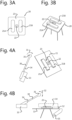
- An exemplary supporting system in accordance with the present invention is shown in top view in fig. 3A and in perspective view in fig. 3B .
- a measurement method according to the present invention is illustrated in figs. 4A and 4B .
- FIGS 1A and 1B illustrate a positioning table in accordance with the present invention.
- the table (10) comprises a piece holder comprising an essentially flat surface (11) and a set of positioning flanges (12, 13) which define the predetermined holder position for a solid piece (14).
- the piece holder is rotatably arranged around a pivot axis (15).
- the actuator is not shown on the figure, but can preferably a motor, such as an electrical motor, preferably a rotating motor, such as an electrical rotating motor.
- the actuator is operably connected to the piece holder and is configured to rotate the piece holder around the pivot axis in a manner consistent with the present invention.
- the piece holder also preferably contains a central hole (16) within the essentially flat surface, which will allow to rotate the piece holder at least partially over the support system, such that the solid piece (14) in de holder position can be gently positioned on top of the support system.
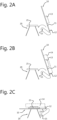
- FIG. 2A This is better illustrated in figures 2A, 2B and 2C , wherein the movement of the rotatable piece holder (10) and the transfer of the solid piece to the supporting system (20) is shown from a side view.
- a solid piece (14) can be positioned on the piece holder at the predetermined holder position ( fig. 2B ) at the beginning of the measurement.
- the flanges (12,13) hold the solid piece in this holder position during the transfer.
- the piece holder is then rotated (counter-clockwise in the figures 2A-2B ).
- the central hole in the piece holder is hereby rotated over the top part (21) of the supporting system (20), the result of which is that the solid piece (14) is placed on the supporting system, and in particular on the top part (21) thereof (see fig. 2C ).
- the top part comprises a flat bed support comprising an elasticity which is much larger than the elasticity of the solid piece to minimize external friction during the measurement.
- the supporting system (20) hereby comprises a solid frame (23) and a top part (21) which preferably comprises a set of flat bed supports (21A, 21B), which preferably are made of elastic material, e.g. a foam.
- a sensor (22) is integrated in the solid frame of the supporting structure in between the flat bed supports. In the shown figure, the predetermined support position is on top of the flat bed supports (21A, 21B) and centralized over the sensor (22).
- the senor may comprise a contact-based sensor such as a piezoelectric sensor, a noncontact-based sensor such as a microphone or a laser vibrometer, or an accelerometer.
- a noncontact-based sensor is preferred if damping parameters are to be measured.
- the acoustic sensor comprises a laser interferometer.
- a laser interferometer is particularly useful for measurements in vacuum, and allows contactless measurements.
- the acoustic sensor may comprise an ultrasonic measurement sensor and/or a time-of-flight sensor and/or a Doppler-based sensor, for instance as described in:
- the measurement method is illustrated in figs. 4A and 4B , for a supporting structure as in figures 3A and 3B and a positioning table as shown in figs. 1A-2C .
- the positioning table is hereby in the position shown in fig. 2C , whereby the central hole (16) of the positioning table is rotated over the top part (21) of the supporting system, such that the solid piece (14) is supported only by the top parts (21A, 21B).
- a mechanical impactor (30) is rotated in a first movement (31) over the solid piece (14) as indicated in fig. 4A .
- the mechanical impactor (30) comprises an elastic arm (34) and a hammer tip (35) at a distal end of the arm.
- the mechanical impactor is preferably actuated by an impactor actuator (33) which preferably comprises an electrical motor, preferably a programmable electric motor.
- an impactor actuator (33) which preferably comprises an electrical motor, preferably a programmable electric motor.
- an impulse impact is provided to the solid piece by an up-and-down movement (32) of the arm (34) and hammer tip (35) as indicated in fig. 4B . Only the hammer tip impacts on the solid piece.
- the vibrational response is obtained by the sensor (22), and can be further analyzed by a processing means.
- the positioning table (10) is provided with a temperature sensor for measuring the temperature of the test piece.
- the piece holder of the positioning table is provided with the temperature sensor. This allows the temperature of the test piece to be measured by direct contact.
- the temperature sensor comprises a thermocouple.
- providing the positioning table, and in particular the piece holder, with the temperature sensor allows measuring the temperature of the test piece from the moment it is positioned on the positioning table at least until the moment when the test piece is supported by the support system alone, i.e. from step a) up to step d) of the method according to the present invention, thus allowing measurement of the temperature at any moment or any interval during steps a) to d).
- the temperature may also be measured after step f), in case the test piece is removed from the supporting position by the positioning table.
- the IE measurement method comprises the step of measuring the temperature of the test piece.
- the temperature of the test piece can be measured at any time or during any interval during steps a) up to d), preferably during and/or after performing step a), before, during and/or after performing any of the steps b) and/or c), and/or before and/or during performing step d).
- the temperature of the test piece is monitored during an interval wherein any or any combination of the steps a), b), c) and/or d) are performed, preferably wherein all steps a) to d) are performed.
- the analysis may preferably comprise the following steps:
- a set of attenuations are also extracted from the vibrational response, each of said attenuations corresponding to an eigenfrequency of said set of eigenfrequencies.
- These attenuations can be extracted for at least one and preferably each of the eigenfrequencies.
- at least one damping parameter is computed from an attenuation corresponding to said eigenfrequency, thereby obtaining a microcrack quantity value of the solid piece which allows detecting deviating AM process behaviour which is not detected by the eigenfrequency shift alone.
- an attenuation relates to how a certain eigenfrequency echoes after the impact has been provided to the solid piece, and in particular to how long after the impact said eigenfrequency can still be seen in the vibrational response.
- the attenuation can be extracted from the time domain response of the vibrational response and/or from the frequency domain response of the vibrational response, preferably from the frequency domain response.
- a damping parameter also referred to as a damping coefficient, can be computed from the attenuation.
- attenuation can be quantified by looking at the eigenfrequency peak in the frequency spectrum of the vibrational response.
- a damping parameter is related to a width of the eigenfrequency peak in the vibrational response, e.g.
- a damping parameter can be related to the shape of the eigenfrequency peak in the vibrational response, e.g. a skew damping parameter and/or a kurtosis parameter.
- the eigenfrequency shift thus obtained relates directly to the porosity of the solid piece, which on its turn relates to the amount of voids comprising a medium-sized and large-sized radius. Further, the inventors have found that the damping parameter of an eigenfrequency is intimately related to the amount of microcracks within the solid piece, which on its turn is related to the durability of the solid piece, i.e. the long-term strength. Note that microcracks are essentially linear in structure, and therefore do not significantly contribute to the porosity of the solid piece.
- the present invention allows to obtain information on both porosity and microcracks in a single measurement and/or with a single measurement setup, and thus also allows obtaining a quantitative assessment of the quality of the solid piece based on the eigenfrequency shift and the damping parameter.
- This quantitative assessment also applies to the AM method used to make the solid piece.
- the quantitative assessment may be preferably made by a scoring algorithm, which computes a score depending on the values of the one or more eigenfrequency shifts and the one or more damping parameters, and optionally dependent on a set of threshold values which preferably are selected to ensure a minimum quality of the solid piece.
- the analysis is preferably performed by a processing means, which is configured to:
- the processing means is also configured to obtain a set of attenuations from the vibrational response, each of said attenuations corresponding to an eigenfrequency of said set of eigenfrequencies. These attenuations can be extracted for at least one and preferably each of the eigenfrequencies.
- the processing means is configured, for at least one eigenfrequency, to compute at least one damping parameter from an attenuation corresponding to said eigenfrequency, thereby obtaining a microcrack quantity value of the solid piece.
Landscapes
- Physics & Mathematics (AREA)
- General Physics & Mathematics (AREA)
- Chemical & Material Sciences (AREA)
- Immunology (AREA)
- General Health & Medical Sciences (AREA)
- Pathology (AREA)
- Health & Medical Sciences (AREA)
- Life Sciences & Earth Sciences (AREA)
- Analytical Chemistry (AREA)
- Biochemistry (AREA)
- Engineering & Computer Science (AREA)
- Signal Processing (AREA)
- Manufacturing & Machinery (AREA)
- Materials Engineering (AREA)
- Mathematical Physics (AREA)
- Spectroscopy & Molecular Physics (AREA)
- Acoustics & Sound (AREA)
- Investigating Strength Of Materials By Application Of Mechanical Stress (AREA)
Priority Applications (3)
| Application Number | Priority Date | Filing Date | Title |
|---|---|---|---|
| EP22156669.8A EP4227662A1 (de) | 2022-02-14 | 2022-02-14 | Verbesserter positioniertisch für aufprallerregungsmessungen |
| CN202380020392.5A CN118661086A (zh) | 2022-02-14 | 2023-02-14 | 用于冲击激发测量的改进的定位台 |
| PCT/EP2023/053642 WO2023152399A1 (en) | 2022-02-14 | 2023-02-14 | Improved positioning table for impact excitation measurements |
Applications Claiming Priority (1)
| Application Number | Priority Date | Filing Date | Title |
|---|---|---|---|
| EP22156669.8A EP4227662A1 (de) | 2022-02-14 | 2022-02-14 | Verbesserter positioniertisch für aufprallerregungsmessungen |
Publications (1)
| Publication Number | Publication Date |
|---|---|
| EP4227662A1 true EP4227662A1 (de) | 2023-08-16 |
Family
ID=85477862
Family Applications (1)
| Application Number | Title | Priority Date | Filing Date |
|---|---|---|---|
| EP22156669.8A Withdrawn EP4227662A1 (de) | 2022-02-14 | 2022-02-14 | Verbesserter positioniertisch für aufprallerregungsmessungen |
Country Status (3)
| Country | Link |
|---|---|
| EP (1) | EP4227662A1 (de) |
| CN (1) | CN118661086A (de) |
| WO (1) | WO2023152399A1 (de) |
Citations (8)
| Publication number | Priority date | Publication date | Assignee | Title |
|---|---|---|---|---|
| US6347542B1 (en) * | 1996-06-17 | 2002-02-19 | Dynalyze Ab | Method and arrangement for non-destructive determination of the properties of an object |
| US20100064810A1 (en) * | 2008-09-18 | 2010-03-18 | Microtec S.R.L. | Method and apparatus for identifying the modulus of elasticity of logs |
| EP3309544A1 (de) | 2016-10-11 | 2018-04-18 | General Electric Company | Verfahren und system zur in-prozess-überwachung und -qualitätskontrolle von generativ gefertigten teilen |
| US20190234908A1 (en) | 2018-01-31 | 2019-08-01 | Hexagon Technology Center Gmbh | Oscillation analysis on an object produced by means of additive manufacturing |
| US20200057030A1 (en) | 2015-11-13 | 2020-02-20 | Honeywell Federal Manufacturing & Technologies, Llc | System and method for inspecting parts using dynamic response function |
| EP3658868A1 (de) | 2017-07-27 | 2020-06-03 | GrindoSonic BVBA | Vorrichtung und verfahren zur durchführung einer stosserregungstechnik |
| WO2020153848A1 (en) * | 2019-01-25 | 2020-07-30 | Brookhuis Applied Technologies B.V. | Automated grading of elongated wooden objects |
| WO2020254698A1 (en) | 2019-06-20 | 2020-12-24 | Grindosonic Bvba | Method and system for analysing a test piece using a vibrational response signal |
-
2022
- 2022-02-14 EP EP22156669.8A patent/EP4227662A1/de not_active Withdrawn
-
2023
- 2023-02-14 CN CN202380020392.5A patent/CN118661086A/zh active Pending
- 2023-02-14 WO PCT/EP2023/053642 patent/WO2023152399A1/en active Search and Examination
Patent Citations (8)
| Publication number | Priority date | Publication date | Assignee | Title |
|---|---|---|---|---|
| US6347542B1 (en) * | 1996-06-17 | 2002-02-19 | Dynalyze Ab | Method and arrangement for non-destructive determination of the properties of an object |
| US20100064810A1 (en) * | 2008-09-18 | 2010-03-18 | Microtec S.R.L. | Method and apparatus for identifying the modulus of elasticity of logs |
| US20200057030A1 (en) | 2015-11-13 | 2020-02-20 | Honeywell Federal Manufacturing & Technologies, Llc | System and method for inspecting parts using dynamic response function |
| EP3309544A1 (de) | 2016-10-11 | 2018-04-18 | General Electric Company | Verfahren und system zur in-prozess-überwachung und -qualitätskontrolle von generativ gefertigten teilen |
| EP3658868A1 (de) | 2017-07-27 | 2020-06-03 | GrindoSonic BVBA | Vorrichtung und verfahren zur durchführung einer stosserregungstechnik |
| US20190234908A1 (en) | 2018-01-31 | 2019-08-01 | Hexagon Technology Center Gmbh | Oscillation analysis on an object produced by means of additive manufacturing |
| WO2020153848A1 (en) * | 2019-01-25 | 2020-07-30 | Brookhuis Applied Technologies B.V. | Automated grading of elongated wooden objects |
| WO2020254698A1 (en) | 2019-06-20 | 2020-12-24 | Grindosonic Bvba | Method and system for analysing a test piece using a vibrational response signal |
Non-Patent Citations (3)
| Title |
|---|
| J.TAPSON: "High precision, short range ultrasonic sensing by means of resonance mode-locking", ULTRASONICS, vol. 33, no. 6, 1995, pages 441 - 444, XP000548694, DOI: 10.1016/0041-624X(95)00052-5 |
| R.KAZYSR. SLITERISL. MAZEIKA: "Ultrasonic technique for Vibration Measurements", PROCEEDINGS OF THE 15TH WORLD CONFERENCE ON NON-DESTRUCTIVE TESTING, 15 October 2000 (2000-10-15), Retrieved from the Internet <URL:https://www.ndt.net/article/wcndt00/papers/idn246/idn246.htm> |
| S-R.HUANGR.M.LERNERK.J.PARKER: "Time domain Doppler estimators of the amplitude of vibrating targets", J. ACOUS. SOC. AM., vol. 91, no. 2, 1992, pages 965 - 974 |
Also Published As
| Publication number | Publication date |
|---|---|
| WO2023152399A1 (en) | 2023-08-17 |
| CN118661086A (zh) | 2024-09-17 |
Similar Documents
| Publication | Publication Date | Title |
|---|---|---|
| US11137329B2 (en) | Apparatus and method for performing an impact excitation technique | |
| US12061177B2 (en) | Method and system for analysing a test piece | |
| US10444110B2 (en) | System and method for inspecting parts using frequency response function | |
| US6880379B2 (en) | Method and device for detecting damage in materials or objects | |
| US11073501B2 (en) | System and method for inspecting parts using dynamic response function | |
| JP2020537155A5 (de) | ||
| US7117134B2 (en) | Method to optimize generation of ultrasound using mathematical modeling for laser ultrasound inspection | |
| CN111597653B (zh) | 一种桥式起重机桥架结构缺陷动态检测识别方法 | |
| CN113646122A (zh) | 用于监测超声波焊接质量的方法 | |
| US20240300184A1 (en) | Improved additive manufacturing monitoring method and system | |
| EP4227662A1 (de) | Verbesserter positioniertisch für aufprallerregungsmessungen | |
| JP4500973B2 (ja) | コンクリート構造物の圧縮強度測定方法及び測定装置 | |
| EP4303545A1 (de) | Dichte-asymmetrie-messverfahren und -gerät | |
| JP2011133318A (ja) | 検査装置及びそれを用いた検査方法 | |
| Lewis et al. | Comparison of numerical and ultrasonic techniques for quantifying interference fit pressures | |
| Wada et al. | Integrity assessment of turbine generator rotor wedges based on their resonance characteristics | |
| JP2024509245A (ja) | 衝撃測定のための改善された支持 |
Legal Events
| Date | Code | Title | Description |
|---|---|---|---|
| PUAI | Public reference made under article 153(3) epc to a published international application that has entered the european phase |
Free format text: ORIGINAL CODE: 0009012 |
|
| STAA | Information on the status of an ep patent application or granted ep patent |
Free format text: STATUS: THE APPLICATION HAS BEEN PUBLISHED |
|
| AK | Designated contracting states |
Kind code of ref document: A1 Designated state(s): AL AT BE BG CH CY CZ DE DK EE ES FI FR GB GR HR HU IE IS IT LI LT LU LV MC MK MT NL NO PL PT RO RS SE SI SK SM TR |
|
| STAA | Information on the status of an ep patent application or granted ep patent |
Free format text: STATUS: THE APPLICATION IS DEEMED TO BE WITHDRAWN |
|
| 18D | Application deemed to be withdrawn |
Effective date: 20240217 |