EP0906540B1 - Systeme d'attenuation de vibrations - Google Patents
Systeme d'attenuation de vibrations Download PDFInfo
- Publication number
- EP0906540B1 EP0906540B1 EP97925717A EP97925717A EP0906540B1 EP 0906540 B1 EP0906540 B1 EP 0906540B1 EP 97925717 A EP97925717 A EP 97925717A EP 97925717 A EP97925717 A EP 97925717A EP 0906540 B1 EP0906540 B1 EP 0906540B1
- Authority
- EP
- European Patent Office
- Prior art keywords
- layer
- vibration
- adhesive
- damping system
- viscosity enhancing
- Prior art date
- Legal status (The legal status is an assumption and is not a legal conclusion. Google has not performed a legal analysis and makes no representation as to the accuracy of the status listed.)
- Expired - Lifetime
Links
- 238000013016 damping Methods 0.000 title claims abstract description 59
- 239000000463 material Substances 0.000 claims abstract description 61
- 230000001070 adhesive effect Effects 0.000 claims abstract description 58
- 239000000853 adhesive Substances 0.000 claims abstract description 56
- 230000002708 enhancing effect Effects 0.000 claims abstract description 30
- 238000000034 method Methods 0.000 claims abstract description 14
- 229920003043 Cellulose fiber Polymers 0.000 claims abstract description 6
- 239000010410 layer Substances 0.000 claims description 97
- 239000000835 fiber Substances 0.000 claims description 11
- 239000012790 adhesive layer Substances 0.000 claims description 9
- 239000001913 cellulose Substances 0.000 claims description 7
- NIXOWILDQLNWCW-UHFFFAOYSA-N acrylic acid group Chemical group C(C=C)(=O)O NIXOWILDQLNWCW-UHFFFAOYSA-N 0.000 claims description 5
- 229920000642 polymer Polymers 0.000 claims description 5
- XTXRWKRVRITETP-UHFFFAOYSA-N Vinyl acetate Chemical class CC(=O)OC=C XTXRWKRVRITETP-UHFFFAOYSA-N 0.000 claims description 4
- 239000011248 coating agent Substances 0.000 claims description 4
- 238000000576 coating method Methods 0.000 claims description 4
- 239000007788 liquid Substances 0.000 claims description 4
- 229920000049 Carbon (fiber) Polymers 0.000 claims description 3
- 239000004917 carbon fiber Substances 0.000 claims description 3
- VNWKTOKETHGBQD-UHFFFAOYSA-N methane Chemical compound C VNWKTOKETHGBQD-UHFFFAOYSA-N 0.000 claims description 3
- 239000005011 phenolic resin Substances 0.000 claims description 3
- 229920003051 synthetic elastomer Polymers 0.000 claims description 3
- 239000005061 synthetic rubber Substances 0.000 claims description 3
- 239000004831 Hot glue Substances 0.000 claims description 2
- 229920000877 Melamine resin Polymers 0.000 claims description 2
- 229920001807 Urea-formaldehyde Polymers 0.000 claims description 2
- 239000003822 epoxy resin Substances 0.000 claims description 2
- LNEPOXFFQSENCJ-UHFFFAOYSA-N haloperidol Chemical compound C1CC(O)(C=2C=CC(Cl)=CC=2)CCN1CCCC(=O)C1=CC=C(F)C=C1 LNEPOXFFQSENCJ-UHFFFAOYSA-N 0.000 claims description 2
- 239000003973 paint Substances 0.000 claims description 2
- 229920000647 polyepoxide Polymers 0.000 claims description 2
- 150000003673 urethanes Chemical class 0.000 claims description 2
- 229910052751 metal Inorganic materials 0.000 description 9
- 239000002184 metal Substances 0.000 description 9
- 239000011162 core material Substances 0.000 description 6
- 229920002678 cellulose Polymers 0.000 description 5
- 239000003190 viscoelastic substance Substances 0.000 description 5
- 230000000694 effects Effects 0.000 description 4
- 230000035939 shock Effects 0.000 description 4
- 239000003522 acrylic cement Substances 0.000 description 3
- 239000010426 asphalt Substances 0.000 description 3
- 230000006870 function Effects 0.000 description 3
- 230000008447 perception Effects 0.000 description 3
- XEEYBQQBJWHFJM-UHFFFAOYSA-N Iron Chemical compound [Fe] XEEYBQQBJWHFJM-UHFFFAOYSA-N 0.000 description 2
- 230000008901 benefit Effects 0.000 description 2
- 239000012876 carrier material Substances 0.000 description 2
- 239000003365 glass fiber Substances 0.000 description 2
- 239000011256 inorganic filler Substances 0.000 description 2
- 229910003475 inorganic filler Inorganic materials 0.000 description 2
- 239000007769 metal material Substances 0.000 description 2
- 230000035515 penetration Effects 0.000 description 2
- 239000004033 plastic Substances 0.000 description 2
- 229920003023 plastic Polymers 0.000 description 2
- 238000010008 shearing Methods 0.000 description 2
- 238000005406 washing Methods 0.000 description 2
- RYGMFSIKBFXOCR-UHFFFAOYSA-N Copper Chemical compound [Cu] RYGMFSIKBFXOCR-UHFFFAOYSA-N 0.000 description 1
- 229920001651 Cyanoacrylate Polymers 0.000 description 1
- 229920002430 Fibre-reinforced plastic Polymers 0.000 description 1
- 239000004952 Polyamide Substances 0.000 description 1
- 239000000654 additive Substances 0.000 description 1
- 230000000996 additive effect Effects 0.000 description 1
- 229910052782 aluminium Inorganic materials 0.000 description 1
- XAGFODPZIPBFFR-UHFFFAOYSA-N aluminium Chemical compound [Al] XAGFODPZIPBFFR-UHFFFAOYSA-N 0.000 description 1
- 239000000378 calcium silicate Substances 0.000 description 1
- 229910052918 calcium silicate Inorganic materials 0.000 description 1
- OYACROKNLOSFPA-UHFFFAOYSA-N calcium;dioxido(oxo)silane Chemical compound [Ca+2].[O-][Si]([O-])=O OYACROKNLOSFPA-UHFFFAOYSA-N 0.000 description 1
- 238000003490 calendering Methods 0.000 description 1
- 239000004568 cement Substances 0.000 description 1
- 239000000919 ceramic Substances 0.000 description 1
- 239000004927 clay Substances 0.000 description 1
- 239000002131 composite material Substances 0.000 description 1
- 238000010276 construction Methods 0.000 description 1
- 238000010411 cooking Methods 0.000 description 1
- 229910052802 copper Inorganic materials 0.000 description 1
- 239000010949 copper Substances 0.000 description 1
- 238000007766 curtain coating Methods 0.000 description 1
- NLCKLZIHJQEMCU-UHFFFAOYSA-N cyano prop-2-enoate Chemical class C=CC(=O)OC#N NLCKLZIHJQEMCU-UHFFFAOYSA-N 0.000 description 1
- 238000001035 drying Methods 0.000 description 1
- 239000013013 elastic material Substances 0.000 description 1
- 239000002320 enamel (paints) Substances 0.000 description 1
- 238000001125 extrusion Methods 0.000 description 1
- 239000011151 fibre-reinforced plastic Substances 0.000 description 1
- 239000006260 foam Substances 0.000 description 1
- 230000002452 interceptive effect Effects 0.000 description 1
- 229910052742 iron Inorganic materials 0.000 description 1
- 230000001788 irregular Effects 0.000 description 1
- -1 knife coating Substances 0.000 description 1
- 239000000696 magnetic material Substances 0.000 description 1
- 239000006247 magnetic powder Substances 0.000 description 1
- 150000002739 metals Chemical class 0.000 description 1
- 239000011505 plaster Substances 0.000 description 1
- 229920002647 polyamide Polymers 0.000 description 1
- 229920000728 polyester Polymers 0.000 description 1
- 230000003014 reinforcing effect Effects 0.000 description 1
- 238000005096 rolling process Methods 0.000 description 1
- 239000010454 slate Substances 0.000 description 1
- 238000002791 soaking Methods 0.000 description 1
- 239000007787 solid Substances 0.000 description 1
- 238000005507 spraying Methods 0.000 description 1
- 229910001220 stainless steel Inorganic materials 0.000 description 1
- 239000010935 stainless steel Substances 0.000 description 1
- 230000003068 static effect Effects 0.000 description 1
- 238000010345 tape casting Methods 0.000 description 1
- 239000002023 wood Substances 0.000 description 1
- 230000003245 working effect Effects 0.000 description 1
Images


Classifications
-
- F—MECHANICAL ENGINEERING; LIGHTING; HEATING; WEAPONS; BLASTING
- F16—ENGINEERING ELEMENTS AND UNITS; GENERAL MEASURES FOR PRODUCING AND MAINTAINING EFFECTIVE FUNCTIONING OF MACHINES OR INSTALLATIONS; THERMAL INSULATION IN GENERAL
- F16F—SPRINGS; SHOCK-ABSORBERS; MEANS FOR DAMPING VIBRATION
- F16F9/00—Springs, vibration-dampers, shock-absorbers, or similarly-constructed movement-dampers using a fluid or the equivalent as damping medium
- F16F9/30—Springs, vibration-dampers, shock-absorbers, or similarly-constructed movement-dampers using a fluid or the equivalent as damping medium with solid or semi-solid material, e.g. pasty masses, as damping medium
- F16F9/306—Springs, vibration-dampers, shock-absorbers, or similarly-constructed movement-dampers using a fluid or the equivalent as damping medium with solid or semi-solid material, e.g. pasty masses, as damping medium of the constrained layer type, i.e. comprising one or more constrained viscoelastic layers
-
- F—MECHANICAL ENGINEERING; LIGHTING; HEATING; WEAPONS; BLASTING
- F16—ENGINEERING ELEMENTS AND UNITS; GENERAL MEASURES FOR PRODUCING AND MAINTAINING EFFECTIVE FUNCTIONING OF MACHINES OR INSTALLATIONS; THERMAL INSULATION IN GENERAL
- F16F—SPRINGS; SHOCK-ABSORBERS; MEANS FOR DAMPING VIBRATION
- F16F1/00—Springs
- F16F1/36—Springs made of rubber or other material having high internal friction, e.g. thermoplastic elastomers
- F16F1/37—Springs made of rubber or other material having high internal friction, e.g. thermoplastic elastomers of foam-like material, i.e. microcellular material, e.g. sponge rubber
-
- A—HUMAN NECESSITIES
- A47—FURNITURE; DOMESTIC ARTICLES OR APPLIANCES; COFFEE MILLS; SPICE MILLS; SUCTION CLEANERS IN GENERAL
- A47L—DOMESTIC WASHING OR CLEANING; SUCTION CLEANERS IN GENERAL
- A47L15/00—Washing or rinsing machines for crockery or tableware
- A47L15/42—Details
- A47L15/4209—Insulation arrangements, e.g. for sound damping or heat insulation
-
- A—HUMAN NECESSITIES
- A47—FURNITURE; DOMESTIC ARTICLES OR APPLIANCES; COFFEE MILLS; SPICE MILLS; SUCTION CLEANERS IN GENERAL
- A47L—DOMESTIC WASHING OR CLEANING; SUCTION CLEANERS IN GENERAL
- A47L15/00—Washing or rinsing machines for crockery or tableware
- A47L15/42—Details
- A47L15/4246—Details of the tub
-
- Y—GENERAL TAGGING OF NEW TECHNOLOGICAL DEVELOPMENTS; GENERAL TAGGING OF CROSS-SECTIONAL TECHNOLOGIES SPANNING OVER SEVERAL SECTIONS OF THE IPC; TECHNICAL SUBJECTS COVERED BY FORMER USPC CROSS-REFERENCE ART COLLECTIONS [XRACs] AND DIGESTS
- Y10—TECHNICAL SUBJECTS COVERED BY FORMER USPC
- Y10T—TECHNICAL SUBJECTS COVERED BY FORMER US CLASSIFICATION
- Y10T428/00—Stock material or miscellaneous articles
- Y10T428/249921—Web or sheet containing structurally defined element or component
Definitions
- the present relates to a method and apparatus for vibration (e.g., sound) damping and, in particular, a constrained layer damping system with an enhanced resistance to creep, i.e., the slow lateral movement of the constraining layer relative to a surface of the source of vibration.
- vibration e.g., sound
- constrained layer damping system with an enhanced resistance to creep, i.e., the slow lateral movement of the constraining layer relative to a surface of the source of vibration.
- vibration can have a number of undesirable effects. For instance, consumers are becoming increasingly sensitive to the undesirability of sound created by vibrating systems. Also, vibration can cause electronics, mechanical joints, and fasteners to fail, and can diminish a consumer's perception of quality in a variety of products. For instance, automobile manufacturers have recognized the importance in the purchasing decision of many buyers of a solid thump sound when an automobile door is closed. Likewise, the quality of an appliance is sometimes gauged in part by the perception of the solidity of its construction.
- 3M provides products under the name "ScotchdampTM vibration control systems" in which any one of a variety of adhesive layers joins a constraining layer to a source of vibrating sound.
- the shear modulus and sound loss factors of these products depend on frequency and temperature, as well as on other factors.
- a fundamental problem with vibration damping systems is that it is possible that the constraining layer becomes separated from the surface of the vibration source. In other words, the constraining layer can fall off during shipping or use.
- a shock/shear test has been developed wherein an appliance, for instance, is dropped from a certain distance at a certain angle and temperature, the effect of which on the placement of a constraining layer is measured. If the adhesive properties of the adhesive are insufficient, the constraining layer can become dislodged, potentially causing mishaps within the appliance and, at a minimum, eliminating its damping effect or even perhaps increasing the perception of unwanted vibratory sound.
- the viscoelastic materials have, as one of their properties, a limited fluidity.
- This property of the adhesive can permit the constraining layer to shift laterally with respect to the surface of the vibrating source, particularly when the constraining layer is vertically positioned relative to the vibration source in use.
- the slow movement of the constraining layer relative to the vibration source is referred to herein as "creep" and eventually can lead to catastrophic failure in the form of the constraining layer becoming loose, if the creep goes unchecked.
- the present invention seeks to increase the resistance to creep in vibration damping systems while simultaneously maintaining or increasing the sound damping effect of the constraining layer damping system and maintaining a good resistance to catastrophic failure due to shocks and shearing forces.
- the invention provides also a vibration damping system comprising a constraining layer; and an adhering layer which includes a viscosity enhancing material in the form of organic fibers and an adhesive material.
- JP-62-152750 describes a viscoelastic adhesive comprising vinyl acetate together with an inorganic filler such as glass fibers or clay.
- the viscoelastic material is sandwiched between two layers of metallic material.
- the inorganic filler serves to enhance the adhesive properties of the vinyl acetate to the metallic materials.
- the vibration damping system according to the present invention uses organic fibers to increase resistance to creep and to catastrophic failure.
- FIG 1 illustrates but one example of the vibration damping system of the present invention.
- an appliance 10 such as a washing machine or clothes dryer, includes side panels or surfaces 11.
- the appliance 10 is a clothes dryer including a drum 20 for holding the clothes through various cycles, though any appliance including means capable of performing a function or work (e.g., washing, drying, cooking, etc.) and capable of producing vibration in reaction to the work or an impact can benefit from the invention.
- the panels 11 are typically formed of sheet material such as sheet-metal to which a layer of enamel paint is applied. Left unmodified, these panels 11 tend to vibrate loudly and act as a type of sound generating diaphragm for vibrations developed in the appliance 10 or by objects hitting the surface 11.
- a vibration damping system 100 including a constraining layer 12 and an adhering layer 13.
- the vibration damping system 100 can be applied to one or more surfaces 11, such as to the length of and sightly offset to the center of a top panel (system 100'), to the center of one or both side panels (system 100") to the toe plate (system 100"'), to the bottom panel (system 100"”), etc.
- the location of the vibration damping system 100 depends on the configuration of the parts within the appliance 10. One or more systems 100 are placed where sound is generated and where they do not interfere with other parts.
- the constraining layer 12 is shown as taking the form of an elongated metal bar or rectilinear plate, but can be shaped as a circular, ovoid, square, irregular, etc. shape as desired.
- the constraining layer 12 can include an appropriate configuration to assist in stiffening the surface panel 11.
- Such a stiffening configuration of the constraining layer 12 might be as simple as including bent edges 16 running the length or width of a flat constraining layer 12 ( Figure 2A) or a bend 14 running the length of the constraining layer 12 ( Figure 2C) to provide greater rigidity due to the angled surfaces of the cross-section of the constraining layer 12.
- the bend 14 is shown as chevron shaped, other shapes such as arcuate, rectilinear, etc., shaped may be used if desired.
- the constraining layer can include one or more anti-interference flanges which are designed to prevent the constraining layer 12 from falling into or otherwise interfering with the inner workings of the appliance 10 if the constraining layer is dislodged.
- the system 100' adhered to the inside surface of the top panel 11 of the appliance 10 includes bent edges 16 which further operate as anti-interference flanges running the width of the ends thereof. These flanges 16 tend to restrain the system 100' from rubbing against the drum in the event that it becomes dislodged from the top panel 11.
- the constraining layer 12 may have a large elastic modulus such as a plate made of sheet metal, iron, aluminum, stainless steel, copper, etc., a plastic plate made of phenol resin, polyamide, polycarbonite, polyester, etc., a fiber reinforced plastic plate fabricated by reinforcing the plastic plate using fiber such as glass fiber, carbon fiber, etc., or an inorganic rigid plate such as slate plate, hydrated calcium silicate plate, a plaster board, a fiber mixed cement plate, a ceramic plate, etc., or an organic rigid plate including asphalt, fiber impregnated with asphalt, wood, etc.
- a large elastic modulus such as a plate made of sheet metal, iron, aluminum, stainless steel, copper, etc., a plastic plate made of phenol resin, polyamide, polycarbonite, polyester, etc., a fiber reinforced plastic plate fabricated by reinforcing the plastic plate using fiber such as glass fiber, carbon fiber, etc., or an inorganic rigid plate such as slate plate, hydrated calcium silicate plate, a plaster board, a
- the vibration damping system 100 can be positioned either on the inside or the outside of the appliance 10. If exposed to casual observation, the constraining layer 12 can include a layer of paint and non-functional configurations or profiles for aesthetic purposes.
- the adhering layer 13 is interposed between the constraining layer 12 and the source of vibration such as the panel 11, such that it acts both to adhere the constraining layer 12 to the panel 11 and damp the vibration of the panel 11.
- the adhering layer 13 is composed of a viscosity enhancing material 21 and an adhesive 22, as shown in Figure 2B.
- the viscosity enhancing material 21 enhances the viscosity of the adhesive and thereby creep resistance, but also reinforces the adhesive and thereby increases the adhesive's resistance to shock and shearing forces.
- the adhesive 22 is preferably a viscoelastic material which converts vibration into heat energy by shear forces developed within the viscoelastic material.
- Any suitable viscoelastic adhesive material can be used if it remains viscous after curing.
- the adhesive can be any one or more of the following adhesives: a pressure sensitive hot or cold melt adhesive, an acrylic based adhesive such as acrylic viscoelastic polymers, pressure sensitive damping polymers, adhesive epoxy resins, urea resins, melamine resins, phenol resins, vinyl acetates, cyanoacrylates, urethanes, synthetic rubbers, etc.
- the adhesive can be, for example, any one of a variety of commercial adhesives such as the acrylic adhesive A-1115 from Avery-Dennison, the acrylic adhesive MACtacTM XD-3780 from Morgan Adhesives, the synthetic rubber based hot melt adhesive R-821 from The Reynolds Co., or the acrylic adhesive V-514 from Venture Tape.
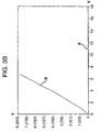
- the performance of these commercially available adhesives is shown in Figure 3A.
- Figure 3A graphically represents an adhesive performance comparison, with respect to inches (mm) of creep (y axis) in a damping system using a cellulose material 21 after allowing for a 60 minute wet out time at 75°F (24°C), where a 150 gram weight was applied to the constraining layer 12 at 125°F (52°C) on painted metal panels over a period of hours (x axis).
- the viscosity enhancing material 21 of the adhering layer 13 generally reduces the fluidity of the resulting adhesive layer, thereby generally reducing the amount of both static and dynamic creep exhibited within the vibration damping system.
- the viscosity enhancing material 21 may include one or more of the following exemplary organic fibers: cellulose, and carbon fiber.
- the viscosity enhancing material 21 provides a structure interposed between the vibration generating source such as the side surface panel 11 of an appliance 10 and the constraining layer 12.
- This structure permits side surface panel 11 and the constraining layer 12 to move relative to one another within confines but increases the viscosity (i.e., resistance to flow) of the adhering layer 13 so that permanent shifts between the constraining layer 12 and the side surface panel 11 are reduced.
- the constraining layer 12 in general does not creep relative to the side surface panel 11 as much as in an identical damping system that doesn't include the viscosity enhancing material 21.
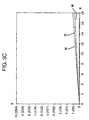
- FIG. 3B This advantage of the present invention is shown in Figure 3B, which demonstrates that the viscosity enhancing material, namely cellulose fiber (a paper-like product), greatly increases the damping system's resistance to creep of the constraining layer (see line A) compared to a substantially similar system (e.g., a system including the same MACtacTM XD-3780 adhesive, the same surface 11 and the same constraining layer 12 with a 150 gram weight applied 90 to the surface plane at 125°F (52°C) but without an additive such as a viscosity enhancing material (see line B).
- a substantially similar system e.g., a system including the same MACtacTM XD-3780 adhesive, the same surface 11 and the same constraining layer 12 with a 150 gram weight applied 90 to the surface plane at 125°F (52°C) but without an additive such as a viscosity enhancing material (see line B).
- a substantially similar system e.g., a system
- the viscosity enhancing material 21 of the adhering layer 13 is a cellulose material, the fibers of which are dimensioned and matted to permit penetration of the adhesive in its liquid state into the cellulose carrier material, which may be accomplished by soaking the cellulose material in the adhesive, by pressurized extrusion, by rolling, or by any other suitable method. The penetration can be within microns or throughout the cellulose material.
- the adhering layer 13 is produced by applying an adhesive 22 in a liquid state to the viscosity enhancing material 21 and curing the adhesive 22 to form an adhesive coated core.
- a number of processes can be used to apply the adhesive 22 to the viscosity enhancing material 21 or to carrier materials.
- appropriate release films 15 may be formed or placed on the major surfaces (top and bottom) of the adhesive coated core or adhering layer 13 in a known fashion.
- the inventive method includes providing a constraining layer 12, providing an adhering layer 13 including a viscosity enhancing material 21 and an adhesive 22, and adhering the constraining layer 12 to the surface of the appliance with the adhering layer 13.
- a first release film 15 is (if present) removed to expose an adhesive coated surface of the adhering layer 13
- the adhering layer 13 is applied to the constraining layer 12 with some application of pressure
- a second release film 15 is removed to expose the opposite adhesive coated surface of the adhering layer 13, and the opposite surface of the adhering layer 13 is applied to the side surface panel 11 of the appliance 10 with some pressure.
- the adhering layer 13 can be applied to the side surface panel 11 initially and the constraining layer 12 applied to the opposing surface of the adhering layer 13 thereafter.
- the actual application of the damping system 100 to the panel 11 can include using a roller or a hand to apply pressure on the constraining layer 12, the adhering layer 13, or the panel 11 on one side with the adhesive layer 11 on the other and pinched against a hard surface.
- the various processes should not make a significant difference to the creep resistance of the adhering layer 13.
- the amount of pressure e.g.
- the present invention reduces the amount of creep caused by a force normal to a surface of the constraining layer 12 relative to the side surface panel 11.
- These tests were conducted for, e.g., MACtacTM XD-3780 and Avery 1115 adhesives for various wet-out times, wet-out temperatures, and test temperature conditions on painted metal panels.
- the cellulose fiber core forming the viscosity enhancing material 21 in these tests had a thickness of 4.2 mils and the coat weight of adhesive of 2.35 mils (acrylic) on either side.
- the total thickness of the adhering layer 13 was approximately 8.9 mils. Minor variations ( ⁇ 10%) in these dimensions are assumed and some tolerance for their thickness is to be expected and is acceptable.
- This material passed a shock/shear test of dropping a 3"x8" (76 mm x 203 mm) galvanized constraining layer with full adhesive coverage adhered to a 4"x10" (102 mm x 254 mm) painted panel after a wet out time of 30 min. at 120° F (49°C) from 72 inches (1829 mm).
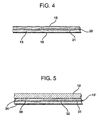
- the adhering layer 13' includes two or more sublayers, including one or more damping layers 30 composed of a viscosity enhancing material 31 and a viscoelastic damping material 32, and one or more adhesive layers 34 composed of an adhesive material.
- the viscoelastic damping material 32 may be any suitable viscoelastic material, such as a polymer, asphalt, etc.
- the viscosity enhancing and adhesive materials may be any suitable materials, such as those disclosed hereinabove.
- the adhesive material be relatively viscous and thus resistant to creep, such that the adhering function of the adhering layer 13 is performed mostly by the adhesive layers 34, and the damping function of the adhering layer 13 is performed mostly by the damping layer 30.
- the adhering layer 13' may include various arrangements of damping layers and adhesive layers other than the arrangement shown in Figure 5, to meet specific design criteria for a particular use of the vibration damping system 100.
- the present invention has been described by way of preferred embodiments. However, the invention is not limited to those preferred embodiments.
- the present invention is applicable to any vibrating system which requires damping on any surface.
- the present invention can have application for damping vibration in the panels of automobile doors, trunks, hoods, etc. and aeronautical applications.
- Application of the invention to such electronic devices as housings for computers or other vibration sensitive equipment is also envisioned.
- the present invention can be applied anywhere vibration or sound damping is appropriate, particularly where the vibration damping element is applied to a horizontal or vertical surface or subjected to any force which might cause a slow shift in the relative position of the damping element (creep) that may or may not lead to catastrophic failure of the adhesive bond.
Landscapes
- Engineering & Computer Science (AREA)
- General Engineering & Computer Science (AREA)
- Mechanical Engineering (AREA)
- Vibration Prevention Devices (AREA)
- Laminated Bodies (AREA)
- Lining Or Joining Of Plastics Or The Like (AREA)
- Buildings Adapted To Withstand Abnormal External Influences (AREA)
- Bridges Or Land Bridges (AREA)
Claims (15)
- Procédé d'amortissement de vibration dans un dispositif de production de vibration, en faisant adhérer une couche de contrainte (12) à une surface (11) du dispositif de production de vibration au moyen d'une couche adhérente (13) qui comprend une matière d'augmentation de la viscosité sous la forme de fibres organiques et une matière adhésive, caractérisé en ce que la matière d'augmentation de la viscosité se présente sous la forme de fibres organiques.
- Procédé selon la revendication 1, dans lequel la matière adhésive (22) comprend au moins l'une des matières suivantes : un adhésif thermofusible sensible à la pression, un adhésif à base acrylique tel que des polymères viscoélastiques acryliques, des polymères d'amortissement sensibles à la pression, des résines époxy adhésives, des résines d'urée, des résines de mélamine, des résines de phénol, des acétates de vinyle, des cyanacrylates, des uréthanes, et des caoutchoucs synthétiques.
- Procédé selon la revendication 1 ou 2, dans lequel la couche adhérente (13) est formée en appliquant une matière adhésive à l'état liquide sur la matière d'augmentation de la viscosité et en laissant l'adhésif durcir.
- Procédé selon l'une quelconque des revendications 1 à 3, dans lequel la couche adhésive est pourvue d'un film de séparation sur sa surface principale, lequel est enlevé pour permettre à la couche de contrainte d'adhérer à la surface du dispositif de production de vibration.
- Procédé selon l'une quelconque des revendications 1 à 4, dans lequel la couche de contrainte (12) est amenée à adhérer à une surface exposée du dispositif de production de vibration, la couche de contrainte comprenant un revêtement de peinture sur au moins l'une de ses faces.
- Procédé selon l'une quelconque des revendications 1 à 4, dans lequel la couche de contrainte est amenée à adhérer à une surface intérieure du dispositif de production de vibration.
- Système d'amortissement de vibration comprenant une couche de contrainte (12) ; et une couche adhérente (13) qui comprend une matière d'augmentation de la viscosité et une matière adhésive, caractérisé en ce que la matière d'augmentation de la viscosité se présente sous la forme de fibres organiques.
- Système d'amortissement de vibration selon la revendication 7, dans lequel la matière d'augmentation de la viscosité (21) comprend au moins l'une des matières suivantes : la cellulose et/ou une fibre de carbone.
- Système d'amortissement de vibration selon la revendication 8, dans lequel la couche adhérente comprend une matière d'augmentation de la viscosité à base de fibres de cellulose dans laquelle la matière adhésive a pénétré.
- Système d'amortissement de vibration selon l'une quelconque des revendications 7 à 9, dans lequel la couche adhérente (13) est viscoélastique.
- Système d'amortissement de vibration selon les revendications 7 à 10, dans lequel la couche adhérente comprend en outre au moins une couche contenant la matière d'augmentation de la viscosité et au moins une couche adhésive comprenant une matière adhésive.
- Système d'amortissement de vibration selon l'une quelconque des revendications 7 à 11, dans lequel la couche adhérente fait preuve d'une résistance au fluage inférieure à 2,54 cm (un pouce) de déplacement en dix heures lorsqu'une force constante d'au plus 150 grammes est appliquée à 52° C (125° F).
- Système d'amortissement de vibration selon l'une quelconque des revendications 7 à 12, comprenant une matière adhésive visqueuse.
- Dispositif de production de vibration comprenant :des moyens pour effectuer un travail ;au moins une surface (11) produisant un son en réponse à une vibration ; etun système d'amortissement de vibration (100), selon l'une quelconque des revendications 7 à 13 dont la couche de contrainte adhère à la surface (11) sous l'effet de la couche adhérente (13).
- Appareil d'amortissement de vibration selon la revendication 13, dans lequel la couche de contrainte du système d'amortissement de vibration comprend une matière qui résiste à la flexion plus que la surface à laquelle elle adhère.
Applications Claiming Priority (3)
| Application Number | Priority Date | Filing Date | Title |
|---|---|---|---|
| US08/656,658 US5855353A (en) | 1996-05-31 | 1996-05-31 | Vibration damping system |
| US656658 | 1996-05-31 | ||
| PCT/US1997/008771 WO1997045671A1 (fr) | 1996-05-31 | 1997-05-23 | Systeme d'attenuation de vibrations |
Publications (3)
| Publication Number | Publication Date |
|---|---|
| EP0906540A1 EP0906540A1 (fr) | 1999-04-07 |
| EP0906540A4 EP0906540A4 (fr) | 2001-06-13 |
| EP0906540B1 true EP0906540B1 (fr) | 2004-01-28 |
Family
ID=24634001
Family Applications (1)
| Application Number | Title | Priority Date | Filing Date |
|---|---|---|---|
| EP97925717A Expired - Lifetime EP0906540B1 (fr) | 1996-05-31 | 1997-05-23 | Systeme d'attenuation de vibrations |
Country Status (15)
| Country | Link |
|---|---|
| US (1) | US5855353A (fr) |
| EP (1) | EP0906540B1 (fr) |
| JP (1) | JP2001518168A (fr) |
| CN (1) | CN1220727A (fr) |
| AT (1) | ATE258664T1 (fr) |
| AU (1) | AU718282B2 (fr) |
| BR (1) | BR9709365A (fr) |
| CA (1) | CA2253849C (fr) |
| CO (1) | CO4700566A1 (fr) |
| DE (1) | DE69727379T2 (fr) |
| NZ (1) | NZ332646A (fr) |
| TR (1) | TR199802454T2 (fr) |
| TW (1) | TW348207B (fr) |
| WO (1) | WO1997045671A1 (fr) |
| ZA (1) | ZA974613B (fr) |
Families Citing this family (49)
| Publication number | Priority date | Publication date | Assignee | Title |
|---|---|---|---|---|
| DE10031318C2 (de) * | 2000-06-28 | 2003-12-24 | Alcan Gmbh | Schall- und schwingungsdämpfendes Metallband, Formteil und Verfahren zur Herstellung eines schall- und schwingungsdämpfenden Metallbandes |
| KR100353026B1 (ko) * | 2000-07-20 | 2002-09-16 | 삼성전자 주식회사 | 세탁기의 캐비넷 |
| GB2365945B (en) * | 2000-08-16 | 2004-02-11 | Rolls Royce Plc | A vibration damping system and a method of damping vibrations |
| DE60224217D1 (de) * | 2001-10-05 | 2008-01-31 | Emerson Electric Co | Geräuschreduzierte speisereste-entsorgungsvorrichtung |
| US6807700B2 (en) * | 2002-07-09 | 2004-10-26 | Owens Corning Fiberglass Technology, Inc. | Acoustical laundry tub blanket |
| US20040219322A1 (en) * | 2002-08-14 | 2004-11-04 | Fisher Dennis K. | Self-adhesive vibration damping tape and composition |
| US7094478B1 (en) | 2002-09-13 | 2006-08-22 | Material Sciences Corporation, Engineered Materials And Solutions Group, Inc. | Magnetic damping |
| ATE408712T1 (de) * | 2003-01-10 | 2008-10-15 | Millennium Pharm Inc | Verfahren zur bestimmung des wiederauftretens von prostata krebs |
| JP2005134653A (ja) * | 2003-10-30 | 2005-05-26 | Kobe Steel Ltd | 吸音構造体 |
| US7172800B2 (en) * | 2003-11-03 | 2007-02-06 | Material Sciences Corporation | Sheet molding compound damper component, and methods for making and using the same |
| WO2006030555A1 (fr) * | 2004-09-15 | 2006-03-23 | Kazuo Uejima | Tapis pour appareil acoustique |
| KR20060064311A (ko) * | 2004-12-08 | 2006-06-13 | 삼성전자주식회사 | 동흡진기를 구비하는 세탁기 |
| KR100726653B1 (ko) | 2004-12-24 | 2007-06-08 | 엘지전자 주식회사 | 플라즈마 표시장치 |
| US7369245B2 (en) * | 2005-05-27 | 2008-05-06 | Honeywell International, Inc. | Sensing coil assembly and method for attaching a sensing coil in a fiber optic gyroscope |
| US20070102029A1 (en) * | 2005-11-04 | 2007-05-10 | Panther Allen L | Acoustic seal for use in kitchen appliance |
| DE102006004349B3 (de) * | 2006-01-30 | 2007-01-25 | Miele & Cie. Kg | Gehäuse für ein Haushaltgerät mit Lärmdämmung |
| US7950609B2 (en) * | 2006-08-18 | 2011-05-31 | Kellogg Brown & Root Llc | Acoustic dampening pipe shoe |
| US8505857B2 (en) | 2006-08-18 | 2013-08-13 | Kellogg Brown & Root Llc | Systems and methods for supporting a pipe |
| DE602006012501D1 (de) * | 2006-10-31 | 2010-04-08 | Electrolux Home Prod Corp | Haushaltsgerät |
| DE102007013494A1 (de) * | 2007-03-21 | 2008-09-25 | Zf Friedrichshafen Ag | Gussgehäuse |
| DE102007036960A1 (de) * | 2007-08-04 | 2009-02-05 | Mtu Aero Engines Gmbh | Dämpfungseinrichtung, Schweißanlage zum Rotationsschweißen und Rotationsschweißverfahren |
| US20090205378A1 (en) * | 2008-02-15 | 2009-08-20 | Electrolux Home Products, Inc. | Washing appliance and associated method |
| US20110232701A1 (en) * | 2009-01-27 | 2011-09-29 | Electrolux Home Products, Inc. | Mastic-less dishwasher providing increasing energy efficiency and including a recyclable and reclaimable tub |
| US7981222B2 (en) * | 2009-01-27 | 2011-07-19 | Electrolux Home Prducts, Inc. | Dishwasher having sound attenuating structures |
| CN102481760B (zh) * | 2009-08-11 | 2016-02-24 | 夏伊洛工业公司 | 金属板组件 |
| MX2011009074A (es) * | 2010-01-05 | 2011-09-27 | Owens Corning Intellectual Cap | Capsula de embarque que incorpora manta y metodo. |
| US9506181B2 (en) | 2010-01-05 | 2016-11-29 | Owens Corning Intellectual Capital, Llc | Appliance having dampening portion and method |
| MX2010003431A (es) * | 2010-03-26 | 2011-09-26 | Mabe Sa De Cv | Estampado de gabinete. |
| WO2011119927A2 (fr) * | 2010-03-26 | 2011-09-29 | Owens Corning Intellectual Capital, Llc | Système et procédé d'expédition de machine à laver |
| DE102010031492A1 (de) * | 2010-07-16 | 2012-01-19 | BSH Bosch und Siemens Hausgeräte GmbH | Haushaltsgerät mit mindestens einer Entdröhnungs- und/oder Schallbedämmungsbeschichtung sowie zugehöriges Herstellungsverfahren |
| DE102010031487A1 (de) * | 2010-07-16 | 2012-01-19 | BSH Bosch und Siemens Hausgeräte GmbH | Verfahren zur Herstellung einer Geschirrspülmaschine mit mindestens einer, insbesondere vorkonfektionierten, Bitumenmatte zur Entdröhnung und/oder Schallbedämmung eines Bauteils |
| TWI398352B (zh) * | 2010-10-06 | 2013-06-11 | Daejin Dsp Co Ltd | 具有壓花圖案之裝飾不銹鋼壓延板及其製造方法 |
| US9845564B2 (en) | 2010-12-31 | 2017-12-19 | Owens Corning Intellectual Capital, Llc | Appliance having a housing dampening portion and method |
| CN102182046A (zh) * | 2011-05-19 | 2011-09-14 | 南京乐金熊猫电器有限公司 | 一种洗衣机减振降噪的方法 |
| US9714480B2 (en) | 2011-05-24 | 2017-07-25 | Owens Corning Intellectual Capital, Llc | Acoustically insulated machine |
| CN102433715B (zh) * | 2011-09-23 | 2013-09-04 | 南京乐金熊猫电器有限公司 | 一种洗衣机隔音降噪的方法 |
| KR101964644B1 (ko) * | 2012-05-10 | 2019-04-02 | 엘지전자 주식회사 | 소음저감부가 구비된 가전기기 |
| US9453296B2 (en) | 2013-02-18 | 2016-09-27 | Owens Corning Intellectual Capital, Llc | Acoustically insulated machine |
| US9931016B2 (en) | 2013-10-09 | 2018-04-03 | Owens Corning Intellectual Capital, Llc | Dishwasher insulation blanket |
| CN106231975A (zh) | 2014-03-10 | 2016-12-14 | 欧文斯科宁知识产权资产有限公司 | 洗碗机隔离毯 |
| US9725154B2 (en) * | 2014-05-13 | 2017-08-08 | The Boeing Company | Method and apparatus for reducing structural vibration and noise |
| KR20170020425A (ko) * | 2014-06-18 | 2017-02-22 | 오웬스 코닝 인텔렉츄얼 캐피탈 엘엘씨 | 진동 감쇠 시스템 |
| CN104723029A (zh) * | 2014-07-25 | 2015-06-24 | 芜湖美的洗涤电器制造有限公司 | 内胆制造方法及洗碗机 |
| EP3266921B1 (fr) | 2016-07-07 | 2019-09-04 | LG Electronics Inc. | Appareil de traitement du linge |
| EP3266920B1 (fr) | 2016-07-07 | 2020-09-30 | LG Electronics Inc. -1- | Appareil de traitement du linge |
| CN107587313B (zh) | 2016-07-07 | 2020-08-21 | Lg电子株式会社 | 洗涤物处理装置 |
| JP6740445B2 (ja) * | 2016-07-07 | 2020-08-12 | エルジー エレクトロニクス インコーポレイティド | 洗濯物処理装置 |
| US10458059B2 (en) | 2017-09-06 | 2019-10-29 | Whirlpool Corporation | Basement assembly for reducing noise levels of a household appliance |
| EP4317350A3 (fr) | 2017-12-14 | 2024-03-27 | Avery Dennison Corporation | Adhésif sensible à la pression à large plage de température et de fréquence d'amortissement |
Family Cites Families (25)
| Publication number | Priority date | Publication date | Assignee | Title |
|---|---|---|---|---|
| US3160549A (en) * | 1960-12-29 | 1964-12-08 | Minnesota Mining & Mfg | Vibration damping structures |
| GB1028884A (en) * | 1963-02-25 | 1966-05-11 | Lord Corp | Damped structure |
| US3693750A (en) * | 1970-09-21 | 1972-09-26 | Minnesota Mining & Mfg | Composite metal structure useful in sound absorption |
| DE2653428C3 (de) * | 1976-11-24 | 1979-05-17 | Claus Koenig Kg, 8520 Erlangen | Farbfolie zum Herstellen einer Vorlage für Werbezwecke |
| JPS599332A (ja) * | 1982-07-06 | 1984-01-18 | Bridgestone Corp | 制振材 |
| US4563388A (en) * | 1983-03-28 | 1986-01-07 | Minnesota Mining And Manufacturing Company | Polyolefin substrate coated with acrylic-type normally tacky and pressure-sensitive adhesive and a method of making same |
| US4599257A (en) * | 1984-03-06 | 1986-07-08 | Thomas Wozniak | Method of forming a metal fiberglass interface |
| DE3434298A1 (de) * | 1984-09-19 | 1986-03-27 | Hoechst Ag, 6230 Frankfurt | Transfermetallisierungsfolie |
| JPS62152750A (ja) * | 1985-12-27 | 1987-07-07 | 新日鐵化学株式会社 | 制振材料用粘弾性組成物 |
| US4902546A (en) * | 1986-04-16 | 1990-02-20 | Dennison Manufacturing Company | Transfer metallization laminate |
| US5153042A (en) * | 1989-05-16 | 1992-10-06 | Minnesota Mining And Manufacturing Company | Tamper-indicating labelstock |
| JPH0435938A (ja) * | 1990-05-31 | 1992-02-06 | Minnesota Mining & Mfg Co <3M> | 金属調光沢を有する積層フィルム |
| US5149571A (en) * | 1990-10-11 | 1992-09-22 | Croell Richard C | License plate |
| US5300355A (en) * | 1991-05-31 | 1994-04-05 | Nichias Corporation | Vibration damping material |
| DE4138961A1 (de) * | 1991-11-27 | 1993-06-03 | Ymos Ag Ind Produkte | Maschinenfuss |
| US5256223A (en) * | 1991-12-31 | 1993-10-26 | The Center For Innovative Technology | Fiber enhancement of viscoelastic damping polymers |
| CH684698A5 (fr) * | 1992-10-14 | 1994-11-30 | Colas S A Colas S A | Masse de remplissage pour joint viscoélastique continu pour ouvrage d'art en béton et joint viscoélastique comprenant cette masse de remplissage. |
| US5330814A (en) * | 1993-01-07 | 1994-07-19 | Fewell Takeko N | Flexible protective cover pad |
| US5298694A (en) * | 1993-01-21 | 1994-03-29 | Minnesota Mining And Manufacturing Company | Acoustical insulating web |
| WO1994028080A1 (fr) * | 1993-06-02 | 1994-12-08 | Minnesota Mining And Manufacturing Company | Nouvelles structures composites |
| DE4423479A1 (de) * | 1994-07-05 | 1997-12-04 | Weinsheim Chemie | Wärme und Schall reduzierende Beschichtung |
| JPH0835538A (ja) * | 1994-07-25 | 1996-02-06 | Lintec Corp | 制振・補強シート |
| US5474840A (en) * | 1994-07-29 | 1995-12-12 | Minnesota Mining And Manufacturing Company | Silica-containing vibration damper and method |
| KR100211866B1 (ko) * | 1994-09-01 | 1999-08-02 | 전주범 | 세탁기의 저수조 현가장치 |
| JP2869702B2 (ja) * | 1995-03-29 | 1999-03-10 | ニチアス株式会社 | 拘束型制振材 |
-
1996
- 1996-05-31 US US08/656,658 patent/US5855353A/en not_active Expired - Lifetime
-
1997
- 1997-05-22 TW TW086106872A patent/TW348207B/zh active
- 1997-05-23 AT AT97925717T patent/ATE258664T1/de not_active IP Right Cessation
- 1997-05-23 WO PCT/US1997/008771 patent/WO1997045671A1/fr not_active Ceased
- 1997-05-23 NZ NZ332646A patent/NZ332646A/xx unknown
- 1997-05-23 TR TR1998/02454T patent/TR199802454T2/xx unknown
- 1997-05-23 DE DE69727379T patent/DE69727379T2/de not_active Expired - Lifetime
- 1997-05-23 JP JP54276697A patent/JP2001518168A/ja active Pending
- 1997-05-23 EP EP97925717A patent/EP0906540B1/fr not_active Expired - Lifetime
- 1997-05-23 CN CN97195146A patent/CN1220727A/zh active Pending
- 1997-05-23 CA CA002253849A patent/CA2253849C/fr not_active Expired - Fee Related
- 1997-05-23 BR BR9709365A patent/BR9709365A/pt not_active IP Right Cessation
- 1997-05-23 AU AU30771/97A patent/AU718282B2/en not_active Ceased
- 1997-05-27 ZA ZA9704613A patent/ZA974613B/xx unknown
- 1997-05-29 CO CO97029914A patent/CO4700566A1/es unknown
Also Published As
| Publication number | Publication date |
|---|---|
| NZ332646A (en) | 2000-05-26 |
| CN1220727A (zh) | 1999-06-23 |
| CA2253849A1 (fr) | 1997-12-04 |
| CO4700566A1 (es) | 1998-12-29 |
| EP0906540A4 (fr) | 2001-06-13 |
| EP0906540A1 (fr) | 1999-04-07 |
| JP2001518168A (ja) | 2001-10-09 |
| AU3077197A (en) | 1998-01-05 |
| ATE258664T1 (de) | 2004-02-15 |
| WO1997045671A1 (fr) | 1997-12-04 |
| CA2253849C (fr) | 2006-07-18 |
| DE69727379D1 (de) | 2004-03-04 |
| DE69727379T2 (de) | 2004-11-04 |
| TR199802454T2 (xx) | 2001-12-21 |
| US5855353A (en) | 1999-01-05 |
| AU718282B2 (en) | 2000-04-13 |
| BR9709365A (pt) | 1999-08-10 |
| TW348207B (en) | 1998-12-21 |
| ZA974613B (en) | 1997-12-30 |
Similar Documents
| Publication | Publication Date | Title |
|---|---|---|
| EP0906540B1 (fr) | Systeme d'attenuation de vibrations | |
| US6790520B1 (en) | Vibration dampening laminate | |
| RU2462561C2 (ru) | Стенные и потолочные звукоизолирующие устройства | |
| KR910008868B1 (ko) | 진동 감쇠 재료와 상기 감쇠 재료를 이용한 방음구조 | |
| JP2010517864A5 (fr) | ||
| US20150368852A1 (en) | Vibration damping system | |
| JPS59145143A (ja) | 多層構造を有する被覆物を用いた金属薄板の音響防止並びに補強方法 | |
| US20050019590A1 (en) | Vibration damping material and vibration damper | |
| US20210131115A1 (en) | Floor, wall and ceiling cladding | |
| JP4280206B2 (ja) | レールの防音構造 | |
| KR100499758B1 (ko) | 진동감쇠시스템 | |
| WO1994007689A1 (fr) | Stratifie multicouche | |
| US20090252989A1 (en) | Laminated Viscoelastic Damping Structure And Method Of Making The Same | |
| US5866243A (en) | Composite substrate for waterproofing structure, and waterproofing method and waterproofing structure using such composite substrate | |
| Bevan et al. | Acoustic enhancement using chemistry to formulate a spray-on constrained layer vibration damper | |
| Harris | Vibration Damping Materials | |
| GB2447578A (en) | Composite system for acoustic insulation | |
| Jones et al. | Applied damping treatments | |
| JPH11314304A (ja) | 人工大理石積層板 | |
| JP2507153Y2 (ja) | 部分接着型制振性付与用ステンレス鋼板 | |
| RU2465143C2 (ru) | Модифицированная многослойная виброшумодемпфированная композитная структура | |
| CN114750477A (zh) | 用于车身板件增强的密封件 | |
| WO2005042857A2 (fr) | Traitement de paroi d'attenuation sonore magnetique | |
| JP2000154659A (ja) | ユニットバスの防音構造 | |
| MXPA00004572A (en) | Vibration dampening laminate |
Legal Events
| Date | Code | Title | Description |
|---|---|---|---|
| PUAI | Public reference made under article 153(3) epc to a published international application that has entered the european phase |
Free format text: ORIGINAL CODE: 0009012 |
|
| 17P | Request for examination filed |
Effective date: 19981229 |
|
| AK | Designated contracting states |
Kind code of ref document: A1 Designated state(s): AT BE DE ES FR GB IE IT NL SE |
|
| RIC1 | Information provided on ipc code assigned before grant |
Free format text: 7F 16M 1/00 A, 7F 16F 9/30 B |
|
| A4 | Supplementary search report drawn up and despatched |
Effective date: 20010504 |
|
| AK | Designated contracting states |
Kind code of ref document: A4 Designated state(s): AT BE DE ES FR GB IE IT NL SE |
|
| 17Q | First examination report despatched |
Effective date: 20021115 |
|
| GRAP | Despatch of communication of intention to grant a patent |
Free format text: ORIGINAL CODE: EPIDOSNIGR1 |
|
| GRAS | Grant fee paid |
Free format text: ORIGINAL CODE: EPIDOSNIGR3 |
|
| GRAA | (expected) grant |
Free format text: ORIGINAL CODE: 0009210 |
|
| AK | Designated contracting states |
Kind code of ref document: B1 Designated state(s): AT BE DE ES FR GB IE IT NL SE |
|
| PG25 | Lapsed in a contracting state [announced via postgrant information from national office to epo] |
Ref country code: NL Free format text: LAPSE BECAUSE OF FAILURE TO SUBMIT A TRANSLATION OF THE DESCRIPTION OR TO PAY THE FEE WITHIN THE PRESCRIBED TIME-LIMIT Effective date: 20040128 Ref country code: BE Free format text: LAPSE BECAUSE OF FAILURE TO SUBMIT A TRANSLATION OF THE DESCRIPTION OR TO PAY THE FEE WITHIN THE PRESCRIBED TIME-LIMIT Effective date: 20040128 Ref country code: AT Free format text: LAPSE BECAUSE OF FAILURE TO SUBMIT A TRANSLATION OF THE DESCRIPTION OR TO PAY THE FEE WITHIN THE PRESCRIBED TIME-LIMIT Effective date: 20040128 |
|
| REG | Reference to a national code |
Ref country code: GB Ref legal event code: FG4D |
|
| REG | Reference to a national code |
Ref country code: IE Ref legal event code: FG4D |
|
| REF | Corresponds to: |
Ref document number: 69727379 Country of ref document: DE Date of ref document: 20040304 Kind code of ref document: P |
|
| REG | Reference to a national code |
Ref country code: SE Ref legal event code: TRGR |
|
| PG25 | Lapsed in a contracting state [announced via postgrant information from national office to epo] |
Ref country code: ES Free format text: LAPSE BECAUSE OF FAILURE TO SUBMIT A TRANSLATION OF THE DESCRIPTION OR TO PAY THE FEE WITHIN THE PRESCRIBED TIME-LIMIT Effective date: 20040509 |
|
| PG25 | Lapsed in a contracting state [announced via postgrant information from national office to epo] |
Ref country code: IE Free format text: LAPSE BECAUSE OF NON-PAYMENT OF DUE FEES Effective date: 20040524 |
|
| NLV1 | Nl: lapsed or annulled due to failure to fulfill the requirements of art. 29p and 29m of the patents act | ||
| ET | Fr: translation filed | ||
| PLBE | No opposition filed within time limit |
Free format text: ORIGINAL CODE: 0009261 |
|
| STAA | Information on the status of an ep patent application or granted ep patent |
Free format text: STATUS: NO OPPOSITION FILED WITHIN TIME LIMIT |
|
| 26N | No opposition filed |
Effective date: 20041029 |
|
| REG | Reference to a national code |
Ref country code: IE Ref legal event code: MM4A |
|
| REG | Reference to a national code |
Ref country code: GB Ref legal event code: 732E |
|
| REG | Reference to a national code |
Ref country code: FR Ref legal event code: TP |
|
| PGFP | Annual fee paid to national office [announced via postgrant information from national office to epo] |
Ref country code: FR Payment date: 20110607 Year of fee payment: 15 Ref country code: SE Payment date: 20110527 Year of fee payment: 15 |
|
| PGFP | Annual fee paid to national office [announced via postgrant information from national office to epo] |
Ref country code: GB Payment date: 20110525 Year of fee payment: 15 |
|
| PGFP | Annual fee paid to national office [announced via postgrant information from national office to epo] |
Ref country code: DE Payment date: 20110527 Year of fee payment: 15 Ref country code: IT Payment date: 20110526 Year of fee payment: 15 |
|
| REG | Reference to a national code |
Ref country code: SE Ref legal event code: EUG |
|
| GBPC | Gb: european patent ceased through non-payment of renewal fee |
Effective date: 20120523 |
|
| PG25 | Lapsed in a contracting state [announced via postgrant information from national office to epo] |
Ref country code: SE Free format text: LAPSE BECAUSE OF NON-PAYMENT OF DUE FEES Effective date: 20120524 Ref country code: IT Free format text: LAPSE BECAUSE OF NON-PAYMENT OF DUE FEES Effective date: 20120523 |
|
| REG | Reference to a national code |
Ref country code: FR Ref legal event code: ST Effective date: 20130131 |
|
| REG | Reference to a national code |
Ref country code: DE Ref legal event code: R119 Ref document number: 69727379 Country of ref document: DE Effective date: 20121201 |
|
| PG25 | Lapsed in a contracting state [announced via postgrant information from national office to epo] |
Ref country code: GB Free format text: LAPSE BECAUSE OF NON-PAYMENT OF DUE FEES Effective date: 20120523 Ref country code: FR Free format text: LAPSE BECAUSE OF NON-PAYMENT OF DUE FEES Effective date: 20120531 |
|
| PG25 | Lapsed in a contracting state [announced via postgrant information from national office to epo] |
Ref country code: DE Free format text: LAPSE BECAUSE OF NON-PAYMENT OF DUE FEES Effective date: 20121201 |