EP0905659A1 - Kartenausgeber - Google Patents
Kartenausgeber Download PDFInfo
- Publication number
- EP0905659A1 EP0905659A1 EP97307690A EP97307690A EP0905659A1 EP 0905659 A1 EP0905659 A1 EP 0905659A1 EP 97307690 A EP97307690 A EP 97307690A EP 97307690 A EP97307690 A EP 97307690A EP 0905659 A1 EP0905659 A1 EP 0905659A1
- Authority
- EP
- European Patent Office
- Prior art keywords
- card
- magazine
- dispensing
- cards
- dispensing mechanism
- Prior art date
- Legal status (The legal status is an assumption and is not a legal conclusion. Google has not performed a legal analysis and makes no representation as to the accuracy of the status listed.)
- Withdrawn
Links
Images


Classifications
-
- G—PHYSICS
- G07—CHECKING-DEVICES
- G07F—COIN-FREED OR LIKE APPARATUS
- G07F11/00—Coin-freed apparatus for dispensing, or the like, discrete articles
- G07F11/02—Coin-freed apparatus for dispensing, or the like, discrete articles from non-movable magazines
- G07F11/04—Coin-freed apparatus for dispensing, or the like, discrete articles from non-movable magazines in which magazines the articles are stored one vertically above the other
- G07F11/14—Coin-freed apparatus for dispensing, or the like, discrete articles from non-movable magazines in which magazines the articles are stored one vertically above the other with means for raising the stack of articles to permit delivery of the topmost
Definitions
- the present invention relates to a card dispensing apparatus comprising a card magazine and a card dispensing mechanism for dispensing cards from the magazine.
- Card dispensers are well known. In a typical application, a card of a specific monetary value is purchased from a dispenser and is then used to pay for goods or services.
- a dispensing mechanism includes a roller which rotates so as to peel a card from the bottom of a stack of cards stored in the dispenser and direct it along a path to an exit slot. Rotation of the roller is halted when the trailing edge of the card is free from the roller and the next succeeding card in the stack is about to be engaged, to prevent it from being directed towards the exit slot.
- a disadvantage with this arrangement is that a substantial force is required to remove one card from the bottom of the stack, especially when the dispenser is quite full, as the weight of the whole stack of cards is pressing down against the dispensing mechanism.
- the aforementioned arrangement still has a number of disadvantages, as a substantial force must still be applied by the dispensing mechanism to remove a card from the bottom of the stack as the whole weight of the stack of cards presses down against it, the cards may still adhere to each other and precise control of rotation of the roller is still necessary.
- a card dispensing apparatus is characterised in that the magazine and dispensing mechanism are disposed such that the dispensing mechanism will not be subjected to the weight of the cards in the magazine when the magazine is loaded.
- This may be conveniently achieved by arranging for the magazine to present cards to the dispensing mechanism from below. However, this is not essential and, for instance, the magazine could be arranged to present cards from the side.
- a gravity feed may be employed to present the cards to the dispensing mechanism. For instance, the magazine may rise at an angle to the horizontal, merely sufficient for cards to move by gravity towards the dispensing mechanism.
- biasing means is provided for biasing cards loaded into the magazine towards the dispensing means during a dispensing operation.
- the biasing means comprises spring means such as one or more coil springs.
- the coil spring or springs may be arranged to push against the last card in the magazine.
- the preferred arrangement is for the or each spring to be coupled between a card support in the magazine and a structure near the dispensing mechanism.
- a further problem with conventional card dispensers is that they are prone to tampering.
- a determined thief can insert a tool through the exit slot with the aim of 'hooking' a card in the stack and drawing it out without inserting payment.
- the security means comprises a member configured to hold or push cards in the magazine away from the dispensing mechanism.
- an apparatus includes a magazine empty sensor comprising a recessed portion of a card support or pusher in the magazine and a movable member, the movable member being configured to enter the recessed portion of the card support in the absence of a card supported by the card support.
- the movable member may also serve as the security means when cards are present in the magazine.
- the dispensing mechanism comprises a foot for engaging a card in the magazine.
- the foot preferably has a surface providing enhanced the friction between the foot and a card to be dispensed. This may be achieved by forming at least the card engaging part of the foot from an elastomeric or similar material.
- the foot is preferably configured to slide the engaged card towards a card exit slot without disturbing the next succeeding card in the magazine. This may be accomplished by forming the part of the foot which engages the card in an arc which subtends an angle which is sufficient to ensure that the foot engages a card as it is swept over the stack but is small enough to ensure that contact with the next succeeding card is avoided.
- the foot is preferably driven by a gearwheel and rotates therewith to engage a card in each revolution and slide it towards the card exit slot.
- the dispensing mechanism comprises a cam member driven by the gearwheel to engage the moveable member and cause it to press cards in the magazine away from the dispensing mechanism.
- an additional gearwheel is provided behind the card exit slot for rotation in a direction opposite to the direction of rotation of the gearwheel driving the foot and to contact a topmost card when two cards are slid towards the dispensing slot by the foot at the same time, and push the topmost card back into the magazine.
- a motor driven gearwheel meshes with the additional gearwheel which in turn meshes with the gearwheel driving the foot and the cam member.
- an exit gearwheel is situated adjacent the card exit slot for feeding the card through the exit slot.
- the exit gearwheel is rotatably driven indirectly by the motor-driven gearwheel.
- An apparatus preferably includes a card exit gate, the gate being configured to be opened by a card being dispensed and close automatically behind a card being dispensed.
- Optical sensors are preferably provided for sensing inter alia movement of the foot, movement of the movable member of the magazine empty sensor into the recess in the card support and opening and closing of the card exit gate.
- card shall be taken to mean any planar object which may be dispensed from a dispensing apparatus of the type described.
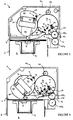
- a card dispensing apparatus 1 comprises a magazine 2 having a chamber 3 for holding a stack of cards 4 and a dispensing mechanism 5 having a housing 5a, disposed above the magazine 2, for directing the top card 6 in the stack 4 along a guide path 7 towards a dispensing slot 8.
- the stack 4 rests on a card support 9 slideably received within the chamber 3.
- the card support 9 is biased by springs (only one shown) 10 located on opposite sides of the magazine 2.
- the springs 10 extend between respective fixed bosses 11 on the housing 5a of the dispensing mechanism 5 and respective bosses 12 on opposite sides of the card support 9 which protrude through respective vertical slots 13 in the side walk of the magazine 2.
- the springs 10 urge the card support 9 and the stack of cards 4 upwardly towards the dispensing mechanism 5.
- a recess 16 is formed in the upper surface 17 of the card support 9 upon which the stack of cards 4 rest.
- the dispensing mechanism 5 disposed above the magazine 3 comprises a primary gearwheel 19 located above the guide path 7 rotatable in a clockwise direction by a motor-riven gearwheel 20.
- the primary gearwheel 19 meshes with a secondary gearwheel 21, positioned above the stack 4 for rotation in an anti-clockwise direction in response to rotation of the primary gearwheel 19 by the motor-driven gear wheel 20.
- the secondary gearwheel 21 carries a foot 22 which extends radially outwardly past the periphery of the secondary gearwheel 21 and has a curved card engaging face 23.
- the foot 22 is made of synthetic rubber.
- a cam member 24 extends radially outwardly past the periphery of the secondary gearwheel 21 radially opposite the foot 22.
- the cam member 24 and the foot 22 both define a circular arc when the secondary gearwheel 21 is caused to rotate and are offset from each other in an axial direction for reasons which will become apparent.
- An exit roller 25a driven by the motor driven gearwheel 20 through the primary gearwheel 19, is situated in the guide path 7 above the exit from the dispensing slot 8.
- the roller 25a is rotatably mounted on a pivotable frame 26 which incorporates an exit gate 25c which extends over the dispensing slot 8.
- the roller 25a is in contact with a pair of spaced idler rollers 25b situated in front of and just below the dispensing slot 8 (see Figure 1) and the exit gate 25c fits in the space between the idler rollers 25b when in its closed position.
- a dipper arm 27 is mounted on a pivot 28 on the housing 5a of the dispensing mechanism 5 offset from its centre of gravity and has a member 29 which rests on, and is supported by, the top card 6 in the stack 4.
- the dipper arm 27 is positioned in axial alignment with the circular arc defined by the cam member 24 during rotation and can engage the upper surface of the member 29 and push it and the stack of cards 4 downwardly in the chamber 3 against the spring bias 10.
- the member 29 drops into the recess 16 in the upper surface 17 of the card support 9 under its own weight.
- Optical sensors 31, 32, 33, 34 are mounted within the dispensing mechanism 5 and transmit signals to a controller (not shown) connected to the dispenser 1 via an electrical terminal block 35 protruding through the housing 2.
- Each optical sensor 31, 32,33,34 comprises a light beam emitting device 31a,32a,33a,34a which directs a beam of light to an associated detector 31b,32b,33b,34b.
- a signal is sent by the optical sensor 31,32,33,34 to the controller.
- Optical sensor 31 detects the position of the foot 22 as it rotates during a dispensing cycle.
- the foot 22 includes a protrusion which passes between the light beam emitting device 31a and the detector 31b of the optical sensor 31 when it reaches its parked position (as shown in Figure 3).
- the optical sensor 31 sends a signal to the controller which deactivates the motor to stop rotation of the motor driven gearwheel 20.
- Optical sensors 32,33 positively determine when the exit gate 25c is open.
- the pivotable frame 26 has a portion which is normally located in the space between the light beam emitting device 32a and detector 32b of optical sensor 32 so that the beam is not detected when the gate 25c is closed.
- the frame 26 pivots. As it does so, the portion moves out of the space between the light beam emitting device 32a and detector 32b of optical sensor 32, so that the beam is now detected, and instead breaks the beam between the light beam emitting device 33a and detector 33b of optical sensor 33.
- a signal is therefore sent by both optical sensor 32 and optical sensor 33 to the controller to provide a positive indication that the exit gate 25c is open.
- the frame 26 pivots back.
- the movement of the frame 26 is again detected by the optical sensors 32,33 and both send a signal to the host controller to provide positive indication that the gate 25c is closed. If the gate 25c remains open for an extended period of time, either because a card has been left in the dispensing slot or a fraud attempt is in progress, the controller may activate an alarm condition.
- the optical sensor 34 works in the same way as the optical sensors 31,32,33, described above, to detect excess movement of the dipper arm 27 as the member 29 drops into the recess 16 in the card support 9 when the last card has been dispensed.
- the other end of the dipper arm 27 pivots upward and breaks the beam between the beam emitting device 34a and detector 34b of optical sensor 34.
- a signal is transmitted by the optical sensor 34 to the machine indicating that the chamber 3 is empty and requires refilling with a fresh stack of cards 4.
- Figure 3 shows the dispensing mechanism 5 in its normal rest or parked position with three cards remaining in the magazine 2.
- the dipper arm 27 has been engaged by the cam member 24 which has pushed the dipper arm 27 and the stack of cards 4 downwardly in the chamber 3 against the spring bias 10 so that the top card 6 is approximately 4mm below the level of the guide path 7 and dispensing slot 8. This makes it very difficult for a thief to remove a card from the chamber 3 by fraudulent means involving the insertion of a tool through the dispensing slot 8.
- Figure 4 shows the dispensing mechanism 5 a short period after activation when the secondary gearwheel 21 has rotated in an anti-clockwise direction by approximately 180 degrees and the foot 22 is just about to come into contact with the top card 6 in the stack 4.
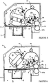
- Figure 5 shows the dispensing mechanism after the secondary gearwheel 21 has rotated further to a position in which the top card 6 in the stack 4 has been contacted by and pushed along the guide path 7 by the foot 22 to a position in which the card 6 is about to pass between the exit roller 25a and the pair of spaced idler rollers 25c.
- the foot 22 is axially offset from the cam member 24 so that the foot 22 does not come into contact with the dipper arm 27 as it rotates and engages the top card 6.
- the curved card engaging face 23 of the foot 22 is of a length which is sufficient to engage the top card in the stack and direct it along the guide path 7 but is short enough to clear the next succeeding card in the stack as the secondary gearwheel 21 continues to rotate. This ensures that only one card is directed along the guide path 7 towards the dispensing slot 8 with each revolution of the secondary gearwheel 22.
- the exit gate 25c As the card passes between the exit roller 25a and the pair of idler rollers 25b, the front edge of the card pushes against the exit gate 25c which causes the frame 26 of which it is a part to pivot upwardly out of the way. Once the card has been taken from the dispensing mechanism 5, the exit gate 25c drops back into its closed position.
- Figure 6 shows the dispensing mechanism 5 after further rotation of the secondary gearwheel 21.
- the foot 22 is no longer in contact with the top card 6 which has partially passed between the exit roller 25a and the spaced idler rollers 25b.
- the driven exit roller 25a now feeds the card 6 further through the dispensing slot 8 and then stops at a predetermined point when a large proportion of the card 6 has passed through, as shown in Figure 7.
- the card 6 is now ready to be taken.
- the secondary gearwheel 21 continues to rotate until it reaches its parked position as shown in Figure 3.
Priority Applications (1)
| Application Number | Priority Date | Filing Date | Title |
|---|---|---|---|
| EP97307690A EP0905659A1 (de) | 1997-09-30 | 1997-09-30 | Kartenausgeber |
Applications Claiming Priority (1)
| Application Number | Priority Date | Filing Date | Title |
|---|---|---|---|
| EP97307690A EP0905659A1 (de) | 1997-09-30 | 1997-09-30 | Kartenausgeber |
Publications (1)
| Publication Number | Publication Date |
|---|---|
| EP0905659A1 true EP0905659A1 (de) | 1999-03-31 |
Family
ID=8229529
Family Applications (1)
| Application Number | Title | Priority Date | Filing Date |
|---|---|---|---|
| EP97307690A Withdrawn EP0905659A1 (de) | 1997-09-30 | 1997-09-30 | Kartenausgeber |
Country Status (1)
| Country | Link |
|---|---|
| EP (1) | EP0905659A1 (de) |
Cited By (6)
| Publication number | Priority date | Publication date | Assignee | Title |
|---|---|---|---|---|
| FR2796186A1 (fr) * | 1999-07-08 | 2001-01-12 | Pascal Borreca | Distributeur de cartes rigides ou relativement rigides |
| US6494365B1 (en) * | 1998-08-20 | 2002-12-17 | Sankyo Seiki Mfg. Co. Ltd. | Card issuing device and method |
| EP1298344A2 (de) | 2001-10-01 | 2003-04-02 | KNORR-BREMSE SYSTEME FÜR NUTZFAHRZEUGE GmbH | Feststellbremsvorrichtung und Verfahren zum Ansteuern der Feststellbremse |
| FR2849006A1 (fr) * | 2002-12-19 | 2004-06-25 | Adhipress | Distributeur d'objets en feuille, tels que cartes ou objets analogues |
| EP1522967A2 (de) * | 2003-10-10 | 2005-04-13 | Proxima S.p.A. | Automatische Couponausgabe- und Verlosungsvorrichtung zur Verwendung in Werbekampagnen |
| WO2016040247A1 (en) * | 2014-09-08 | 2016-03-17 | Electronic Data Magnetics, Inc. | Transaction cards and system |
Citations (5)
| Publication number | Priority date | Publication date | Assignee | Title |
|---|---|---|---|---|
| DE212218C (de) * | ||||
| DE143476C (de) * | ||||
| EP0319046A2 (de) * | 1987-12-03 | 1989-06-07 | Alexandre Martini | Behälter zur Kartenausgabe, insbes. für Visitenkarten |
| CH675863A5 (en) * | 1990-03-13 | 1990-11-15 | Dietmar Hablich | Access card dispenser for vehicle - has roller transfer from magazine activated by user |
| FR2672275A1 (fr) * | 1991-02-01 | 1992-08-07 | Moreau Jacques | Appareil pour distribuer un a un des objets plats tels que des cartes postales, des cartes magnetiques ou des cartes a memoire. |
-
1997
- 1997-09-30 EP EP97307690A patent/EP0905659A1/de not_active Withdrawn
Patent Citations (5)
| Publication number | Priority date | Publication date | Assignee | Title |
|---|---|---|---|---|
| DE212218C (de) * | ||||
| DE143476C (de) * | ||||
| EP0319046A2 (de) * | 1987-12-03 | 1989-06-07 | Alexandre Martini | Behälter zur Kartenausgabe, insbes. für Visitenkarten |
| CH675863A5 (en) * | 1990-03-13 | 1990-11-15 | Dietmar Hablich | Access card dispenser for vehicle - has roller transfer from magazine activated by user |
| FR2672275A1 (fr) * | 1991-02-01 | 1992-08-07 | Moreau Jacques | Appareil pour distribuer un a un des objets plats tels que des cartes postales, des cartes magnetiques ou des cartes a memoire. |
Cited By (9)
| Publication number | Priority date | Publication date | Assignee | Title |
|---|---|---|---|---|
| US6494365B1 (en) * | 1998-08-20 | 2002-12-17 | Sankyo Seiki Mfg. Co. Ltd. | Card issuing device and method |
| FR2796186A1 (fr) * | 1999-07-08 | 2001-01-12 | Pascal Borreca | Distributeur de cartes rigides ou relativement rigides |
| EP1298344A2 (de) | 2001-10-01 | 2003-04-02 | KNORR-BREMSE SYSTEME FÜR NUTZFAHRZEUGE GmbH | Feststellbremsvorrichtung und Verfahren zum Ansteuern der Feststellbremse |
| US6851761B2 (en) | 2001-10-01 | 2005-02-08 | Knorr-Bremse System Fuer Nutzfahrzeuge Gmbh | Parking brake arrangement and method of controlling the parking brake |
| FR2849006A1 (fr) * | 2002-12-19 | 2004-06-25 | Adhipress | Distributeur d'objets en feuille, tels que cartes ou objets analogues |
| EP1522967A2 (de) * | 2003-10-10 | 2005-04-13 | Proxima S.p.A. | Automatische Couponausgabe- und Verlosungsvorrichtung zur Verwendung in Werbekampagnen |
| EP1522967A3 (de) * | 2003-10-10 | 2005-11-23 | Proxima S.p.A. | Automatische Couponausgabe- und Verlosungsvorrichtung zur Verwendung in Werbekampagnen |
| WO2016040247A1 (en) * | 2014-09-08 | 2016-03-17 | Electronic Data Magnetics, Inc. | Transaction cards and system |
| AU2015315444B2 (en) * | 2014-09-08 | 2020-03-05 | Electronic Data Magnetics, Inc. | Transaction cards and system |
Similar Documents
| Publication | Publication Date | Title |
|---|---|---|
| AU559100B2 (en) | Paper currency dispenser friction picker mechanism | |
| JP4497575B2 (ja) | 紙葉収納払出装置 | |
| KR100235851B1 (ko) | 지폐처리기 | |
| US4940162A (en) | Rolled coin dispenser | |
| JP3315335B2 (ja) | 硬貨入出金装置 | |
| US4958825A (en) | Paper let-out apparatus | |
| US4753431A (en) | Note storing apparatus | |
| US6375072B2 (en) | Carrier unit for feeding transaction medium to desired location and automatic transaction system having the carrier unit | |
| EP0905659A1 (de) | Kartenausgeber | |
| US6695689B2 (en) | Detector unit for coin blockage in a coin dispenser | |
| US4450978A (en) | Apparatus for retrieving paper money bills presented but not picked up at automatic teller machine bill delivery station | |
| AU577077B2 (en) | Secure transport construction for banking depository devices | |
| JP2000298749A (ja) | 硬貨一括投入ユニット | |
| US20040069591A1 (en) | Token dispensing and banknote changing device | |
| US6715671B2 (en) | Automatic bill dispensing apparatus with a sorting device | |
| CA1059078A (en) | Change dispensing apparatus | |
| JPH05306028A (ja) | 平たい物品を配給するための装置 | |
| JP3524383B2 (ja) | 紙幣払い出し機 | |
| JP3745525B2 (ja) | カード自動販売機のカード払出口装置 | |
| KR100246988B1 (ko) | 지폐 자동 지급기의 지폐 회수 방법 및 그 장치 | |
| GB2248609A (en) | Apparatus for dispensing from top of stack | |
| KR100232606B1 (ko) | 지폐 보관부내 지폐 유무 감지 장치 | |
| JPH0573761A (ja) | プリペイドカード販売機 | |
| JP4329977B2 (ja) | カード払出し方法及び装置 | |
| JP4301477B2 (ja) | 硬貨搬送装置 |
Legal Events
| Date | Code | Title | Description |
|---|---|---|---|
| PUAI | Public reference made under article 153(3) epc to a published international application that has entered the european phase |
Free format text: ORIGINAL CODE: 0009012 |
|
| AK | Designated contracting states |
Kind code of ref document: A1 Designated state(s): AT BE CH DE DK ES FI FR GB GR IE IT LI LU MC NL PT SE |
|
| AKX | Designation fees paid | ||
| STAA | Information on the status of an ep patent application or granted ep patent |
Free format text: STATUS: THE APPLICATION IS DEEMED TO BE WITHDRAWN |
|
| 18D | Application deemed to be withdrawn |
Effective date: 19991002 |
|
| REG | Reference to a national code |
Ref country code: DE Ref legal event code: 8566 |