EP0905490B1 - Prüfvorrichtung für optische Komponenten - Google Patents
Prüfvorrichtung für optische Komponenten Download PDFInfo
- Publication number
- EP0905490B1 EP0905490B1 EP98107197A EP98107197A EP0905490B1 EP 0905490 B1 EP0905490 B1 EP 0905490B1 EP 98107197 A EP98107197 A EP 98107197A EP 98107197 A EP98107197 A EP 98107197A EP 0905490 B1 EP0905490 B1 EP 0905490B1
- Authority
- EP
- European Patent Office
- Prior art keywords
- optical
- wavelength
- optical component
- tester
- laser source
- Prior art date
- Legal status (The legal status is an assumption and is not a legal conclusion. Google has not performed a legal analysis and makes no representation as to the accuracy of the status listed.)
- Expired - Lifetime
Links
- 230000003287 optical effect Effects 0.000 title claims description 140
- 230000004044 response Effects 0.000 claims description 28
- 230000001419 dependent effect Effects 0.000 claims description 11
- 238000000034 method Methods 0.000 claims description 9
- 238000012545 processing Methods 0.000 claims description 7
- 239000000835 fiber Substances 0.000 claims description 4
- 238000004891 communication Methods 0.000 claims description 3
- 230000003213 activating effect Effects 0.000 claims description 2
- 230000003993 interaction Effects 0.000 claims description 2
- 239000004065 semiconductor Substances 0.000 claims description 2
- 230000011664 signaling Effects 0.000 claims 1
- 238000005259 measurement Methods 0.000 description 15
- 238000012360 testing method Methods 0.000 description 5
- 230000006399 behavior Effects 0.000 description 3
- 230000003595 spectral effect Effects 0.000 description 3
- 238000001228 spectrum Methods 0.000 description 3
- 238000010586 diagram Methods 0.000 description 2
- 239000013307 optical fiber Substances 0.000 description 2
- 229910052691 Erbium Inorganic materials 0.000 description 1
- 238000003491 array Methods 0.000 description 1
- 230000008033 biological extinction Effects 0.000 description 1
- BJQHLKABXJIVAM-UHFFFAOYSA-N bis(2-ethylhexyl) phthalate Chemical compound CCCCC(CC)COC(=O)C1=CC=CC=C1C(=O)OCC(CC)CCCC BJQHLKABXJIVAM-UHFFFAOYSA-N 0.000 description 1
- 238000012937 correction Methods 0.000 description 1
- 230000008878 coupling Effects 0.000 description 1
- 238000010168 coupling process Methods 0.000 description 1
- 238000005859 coupling reaction Methods 0.000 description 1
- UYAHIZSMUZPPFV-UHFFFAOYSA-N erbium Chemical compound [Er] UYAHIZSMUZPPFV-UHFFFAOYSA-N 0.000 description 1
- 230000001747 exhibiting effect Effects 0.000 description 1
- 230000000977 initiatory effect Effects 0.000 description 1
- 238000012986 modification Methods 0.000 description 1
- 230000004048 modification Effects 0.000 description 1
- 238000012805 post-processing Methods 0.000 description 1
- 238000000926 separation method Methods 0.000 description 1
Images

Classifications
-
- G—PHYSICS
- G01—MEASURING; TESTING
- G01M—TESTING STATIC OR DYNAMIC BALANCE OF MACHINES OR STRUCTURES; TESTING OF STRUCTURES OR APPARATUS, NOT OTHERWISE PROVIDED FOR
- G01M11/00—Testing of optical apparatus; Testing structures by optical methods not otherwise provided for
- G01M11/30—Testing of optical devices, constituted by fibre optics or optical waveguides
- G01M11/33—Testing of optical devices, constituted by fibre optics or optical waveguides with a light emitter being disposed at one fibre or waveguide end-face, and a light receiver at the other end-face
Definitions
- a pump coupler at the input of an optical amplifier may have a spectral bandwidth of 50 nm or more, whereas a Wavelength-Division-Multiplexing (WDM) de-multiplexer may have a spectral bandwidth of only 0.2 nm for each of its channels.
- WDM Wavelength-Division-Multiplexing
- modem optical devices such as WDM or Dense-WDM (DWDM) devices, may provide one input and multiple outputs, where each output has a different wavelength passband characteristics. A measurement of such a device often demands several thousand points per output to achieve the required characteristic, with one powermeter per output which have to obtain the measurement points synchronously.
- Known measurement setups for characterizing wavelength dependent optical components are normally based on a tunable laser source in combination with a wavelength meter, a tracking filter and an optical power meter (loc. cit. page 360) and connected via standard interfaces (e.g. HPIB).
- a tunable laser source instead of using a tunable laser source, a broadband light source can be applied in combination with an optical spectrum analyzer (loc cit. page 368f), however, with a limited resolution bandwidth (approximately 0.1...0.05 nm) in contrast to the tunable laser sources (approximately 10 -6 nm).
- EP-A-548 935 discloses an apparatus for measuring the effective refractive index in optical fibers.
- the apparatus comprises a tunable laser source for providing a stimulus signal to the optical component and a receiver for receiving a response of the optical component on the stimulus signal.
- a control unit is coupled to the tunable laser source and the receiver for controlling the functioning thereof.
- the output 20A of the tunable laser source 20 provides the output for applying the stimulus signal to the DUT 100.
- the wavemeter 30 provides an additional output (not shown) for applying the stimulus signal to the DUT 100.
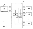
- the signal processor 170 handles the precise time critical emission of triggering signals, so that each laser signals is emitted at a certain (requested) point of time and that each measuring result of the response units 80A...80Z can be clearly assigned to a specific laser input signal for the DUT 100 at a certain wavelength determined by the wavemeter 30.
- the control unit 60 might further comprise a trigger unit (TRIGGER) 200 for emitting trigger signals for activating and initiating respective functionalities of the functional units, such as the tunable laser source 20, the wavemeter 30, the attenuator 40, and the response units 80A...80Z.
- the trigger unit 200 is therefore coupled via a bus 205 with the micro-controller 150, and thus, via the bus 160 to the signal processor 170 and via the bus 70 to the response units 80A...80Z.
- the trigger unit 200 is preferably able to connect internal and/or external modules to each other and is preferably level or edge controlled.
- the trigger unit 200 is preferably embodied in a way that substantially all functionality of the hardware components can be set up and modified by software means, so that the trigger unit 200 is programmable according to the actual demands. This can be accomplished e.g. by using field programmable gate arrays (FPGAs) exhibiting low costs and a low space demand.
- FPGAs field programmable gate arrays
Landscapes
- Physics & Mathematics (AREA)
- Optics & Photonics (AREA)
- Chemical & Material Sciences (AREA)
- Analytical Chemistry (AREA)
- General Physics & Mathematics (AREA)
- Semiconductor Lasers (AREA)
- Testing Of Optical Devices Or Fibers (AREA)
Claims (12)
- Prüfvorrichtung für optische Bauelemente (10) zur Ermittlung der wellenlängenabhängigen Eigenschaften eines optischen Bauelements (100), die Folgendes umfasst:dadurch gekennzeichnet, dassals Funktionseinheiten (20 bis 40, 80):eine abstimmbare Laserquelle (20), um dem optischen Bauelement (100) ein Stimulussignal bereitzustellen, undeine oder mehr Antworteinheiten (80A ... 80Z), um von dem optischen Bauelement (100) eine Antwort auf das Stimulussignal zu empfangen; undeine Steuereinheit (60), die mit den Funktionseinheiten (20 bis 40, 80) verbunden ist, um deren Arbeitsweise zu steuern,
die Steuereinheit (60) einen Mikrocontroller (150) umfasst, der mit einem Signalprozessor (170) verbunden ist, wobei der Signalprozessor (170) mit den Funktionseinheiten (20 bis 40, 80) verbunden und so angeordnet ist, dass er alle zeitkritischen Operationen in der Prüfvorrichtung (10) verarbeitet. - Prüfvorrichtung für optische Bauelemente (10) nach Anspruch 1, wobei die Steuereinheit (60) des Weiteren die Kommunikation zwischen den Funktionseinheiten (20 bis 40, 80) ermöglicht und Informationen für die Interaktion zwischen den Funktionseinheiten (20 bis 40, 80) bereitstellt.
- Prüfvorrichtung für optische Bauelemente (10) nach einem der Ansprüche 1 bis 2, wobei die Steuereinheit (60) eine Triggereinheit (200) umfasst, um Triggersignale zur Aktivierung der Funktionseinheiten (20 bis 40, 80) auszusenden.
- Prüfvorrichtung für optische Bauelemente (10) nach Anspruch 3, wobei die Triggereinheit (200) mit dem Signalprozessor (170) und/oder den Funktionseinheiten (20 bis 40, 80) verbunden ist, um von ihm/ihnen ein Steuereingangssignal zu empfangen und ein Steuerausgangssignal an ihn/sie auszusenden.
- Prüfvorrichtung für optische Bauelemente (10) nach einem der Ansprüche 1 bis 4, die des Weiteren einen Wellenlängenmesser (30) und/oder einen Abschwächer (40) als Funktionseinheiten (20 bis 40, 80) umfasst.
- Prüfvorrichtung für optische Bauelemente (10) nach Anspruch 5, wobei ein Ausgang (20A) der abstimmbaren Laserquelle (20) direkt mit einem Eingang (30A) des Wellenlängenmessers (30) und/oder einem Eingang (40A) des Abschwächers (40) verbunden ist, und wobei ein Ausgang (40B) des Abschwächers (40) einen externen Ausgang der Prüfvorrichtung für optische Bauelemente (10) bereitstellt, um das Stimulussignal an das optische Bauelement (100) anzulegen.
- Prüfvorrichtung für optische Bauelemente (10) nach Anspruch 5 oder 6, wobei die abstimmbare Laserquelle (20) einen optischen Resonator mit einem Halbleiter- und/oder einem Lichtwellenleiter-Verstärker zum Aussenden eines Laserstrahls, einen wellenlängenabhängigen Spiegel, um den Laserstrahl zu empfangen und um einen Laserstrahl mit getrennten Wellenlängen zurückzuwerfen, und einen Strahlteiler umfasst, um den Laserstrahl mit getrennten Wellenlängen in einen auf den Verstärker gerichteten Rückkopplungsstrahl (20A) und einen aus dem optischen Resonator der abstimmbaren Laserquelle (20) auszukoppelnden ersten Ausgangsstrahl (20B) zu teilen.
- Prüfvorrichtung für optische Bauelemente (10) nach einem der Ansprüche 5 bis 7, wobei der Wellenlängenmesser (30) zur Messung einer Wellenlänge eines ersten optischen Strahls Folgendes umfasst:ein erstes optisches Bauelement, das in dem ersten optischen Strahl oder in einem Teil davon angeordnet ist und mit einer ersten optischen Leistung einen zweiten optischen Strahl erzeugt, wobei die erste optische Leistung des zweiten optischen Strahls von der Wellenldnge des ersten optischen Strahls abhängt,einen ersten Leistungsdetektor, der die optische Leistung des zweiten optischen Strahls erkennt,eine erste Zuordnungseinheit, die der erkannten ersten optischen Leistung eine Wellenlänge zuordnet, wobei die Zuordnung auf der Abhängigkeit der optischen Leistung des zweiten optischen Strahls, der von dem ersten optischen Bauelement erzeugt wird, von der Wellenlänge des ersten optischen Strahls, die gemessen werden soll, beruht,ein zweites optisches Bauelement, das in dem ersten optischen Strahl oder in einem Teil davon angeordnet ist und mit einer zweiten optischen Leistung einen dritten optischen Strahl erzeugt, wobei die zweite optische Leistung des dritten optischen Strahls von der Wellenlänge des dritten optischen Strahls abhängt,einen zweiten Leistungsdetektor, der die zweite optische Leistung des dritten optischen Strahls erkennt, undeine zweite Zuordnungseinheit, die der erkannten zweiten optischen Leistung eine Wellenlänge zuordnet, wobei die Zuordnung auf der Abhängigkeit der zweiten optischen Leistung des dritten optischen Strahls, der von dem zweiten optischen Bauelement erzeugt wird, von der Wellenlänge des ersten optischen Strahls, die gemessen werden soll, beruht,wobei die optische Leistung, die von dem ersten und dem zweiten optischen Bauelement erzeugt wird, mit zunehmender Wellenlänge in regelmäßigen Abständen oszilliert, und wobei der dritte optische Strahl in Bezug auf den zweiten optischen Strahl verzögert wird.
- Prüfvorrichtung für optische Bauelemente (10) nach einem der Ansprüche 1 bis 8, wobei die Steuereinheit (60) mit einem Speicher (130) verbunden ist, der gespeicherte Kalibrierdaten, die Daten vor der Kalibrierung und/oder Konfigurationsdaten umfasst.
- Verfahren zur Ermittlung der wellenlängenabhängigen Eigenschaften eines optischen Bauelements (100) mit einer Prüfvorrichtung für optische Bauelemente (10) nach einem der Ansprüche 1 bis 9, wobei das Verfahren die folgenden Schritte umfasst:dem optischen Bauelement (100) wird ein Stimulussignal bereitgestellt,von dem optischen Bauelement (100) wird eine Antwort auf das Stimulussignal empfangen, unddie Bereitstellung des Stimulussignals und der Empfang der Antwort auf das Stimulussignal werden gesteuert, indem die Operationen in der Prüfvorrichtung für optische Bauelemente (10) in zeitkritische und zeitunkritische Operationen aufgeteilt werden.
- Verfahren zur Ermittlung der wellenlängenabhängigen Eigenschaften eines optischen Bauelements (100) nach Anspruch 10, die mit Hilfe einer Prüfvorrichtung für optische Bauelemente (10) durchgeführt wird, wobei die Kalibrierdaten und/oder die Daten vor der Kalibrierung für den Signalprozessor (170) in eine Speichereinheit des Signalprozessors (170) geladen werden.
- Verfahren zur Ermittlung der wellenlängenabhängigen Eigenschaften eines optischen Bauelements (100) mit Hilfe einer Prüfvorrichtung für optische Bauelemente (10) nach einem der Ansprüche 5 bis 9, wobei ein Stimulus und/oder ein Durchlauf der Ansprech-Wellenlänge durchgeführt wird:in einer Betriebsart mit linearen Wellenlängen durch Verwendung des Wellenlängenmessers (30), um die Abstimmung der linearen Wellenlängen der abstimmbaren Laserquelle (20) sicherzustellen, oderin einer Betriebsart mit gleichbleibender Geschwindigkeit durch Umschalten der abstimmbaren Laserquelle (20) von einer ersten Wellenlänge auf eine zweite Wellenlänge, wobei der Wellenlängenmesser (30) die Wellenlänge an jedem Messpunkt misst.
Priority Applications (4)
| Application Number | Priority Date | Filing Date | Title |
|---|---|---|---|
| DE69800492T DE69800492T2 (de) | 1998-04-21 | 1998-04-21 | Prüfvorrichtung für optische Komponenten |
| EP98107197A EP0905490B1 (de) | 1998-04-21 | 1998-04-21 | Prüfvorrichtung für optische Komponenten |
| JP11109099A JP2000035376A (ja) | 1998-04-21 | 1999-04-16 | 光学部品テスタ |
| US09/294,555 US6538778B1 (en) | 1998-04-21 | 1999-04-20 | Optical component tester |
Applications Claiming Priority (1)
| Application Number | Priority Date | Filing Date | Title |
|---|---|---|---|
| EP98107197A EP0905490B1 (de) | 1998-04-21 | 1998-04-21 | Prüfvorrichtung für optische Komponenten |
Publications (2)
| Publication Number | Publication Date |
|---|---|
| EP0905490A1 EP0905490A1 (de) | 1999-03-31 |
| EP0905490B1 true EP0905490B1 (de) | 2001-01-17 |
Family
ID=8231788
Family Applications (1)
| Application Number | Title | Priority Date | Filing Date |
|---|---|---|---|
| EP98107197A Expired - Lifetime EP0905490B1 (de) | 1998-04-21 | 1998-04-21 | Prüfvorrichtung für optische Komponenten |
Country Status (4)
| Country | Link |
|---|---|
| US (1) | US6538778B1 (de) |
| EP (1) | EP0905490B1 (de) |
| JP (1) | JP2000035376A (de) |
| DE (1) | DE69800492T2 (de) |
Families Citing this family (58)
| Publication number | Priority date | Publication date | Assignee | Title |
|---|---|---|---|---|
| US6597449B1 (en) * | 2000-01-31 | 2003-07-22 | New Focus, Inc. | Real time process control of optical components using linearly swept tunable laser |
| JP4842447B2 (ja) * | 2001-03-06 | 2011-12-21 | 株式会社アドバンテスト | 光波長測定装置、方法、プログラムおよび該プログラムを記録した記録媒体 |
| EP1235062B1 (de) * | 2001-11-30 | 2004-03-31 | Agilent Technologies, Inc. (a Delaware corporation) | Messung optischer Multi-Port Vorrichtungen |
| JP2003254864A (ja) | 2002-03-04 | 2003-09-10 | Ando Electric Co Ltd | 波長依存性測定装置 |
| US9867530B2 (en) | 2006-08-14 | 2018-01-16 | Volcano Corporation | Telescopic side port catheter device with imaging system and method for accessing side branch occlusions |
| US8395781B2 (en) | 2007-07-12 | 2013-03-12 | Volcano Corporation | Automatic calibration systems and methods of use |
| US10219780B2 (en) * | 2007-07-12 | 2019-03-05 | Volcano Corporation | OCT-IVUS catheter for concurrent luminal imaging |
| EP2178442B1 (de) | 2007-07-12 | 2017-09-06 | Volcano Corporation | Katheter für in-vivo-bildgebung |
| US9596993B2 (en) | 2007-07-12 | 2017-03-21 | Volcano Corporation | Automatic calibration systems and methods of use |
| JP5481376B2 (ja) | 2007-07-12 | 2014-04-23 | ヴォルカノ コーポレイション | 光コヒーレンストモグラフィー用のクロック制御方法 |
| EP2350602A1 (de) * | 2008-10-27 | 2011-08-03 | Telefonaktiebolaget L M Ericsson (Publ) | Verfahren und vorrichtung zum bestimmen einer signaltransferkenngrösse auf einem lichtpfad in einem optischen netzwerk |
| CN101908942B (zh) * | 2009-06-05 | 2014-10-08 | 华为技术有限公司 | 一种损伤信息传送方法、节点和网络系统 |
| US8233215B2 (en) * | 2009-08-18 | 2012-07-31 | Ciena Corporation | Optical module manufacturing and testing systems and methods |
| US11141063B2 (en) | 2010-12-23 | 2021-10-12 | Philips Image Guided Therapy Corporation | Integrated system architectures and methods of use |
| US11040140B2 (en) | 2010-12-31 | 2021-06-22 | Philips Image Guided Therapy Corporation | Deep vein thrombosis therapeutic methods |
| WO2013033592A1 (en) | 2011-08-31 | 2013-03-07 | Volcano Corporation | Optical-electrical rotary joint and methods of use |
| CA2887421A1 (en) | 2012-10-05 | 2014-04-10 | David Welford | Systems and methods for amplifying light |
| US20140100454A1 (en) | 2012-10-05 | 2014-04-10 | Volcano Corporation | Methods and systems for establishing parameters for three-dimensional imaging |
| US10070827B2 (en) | 2012-10-05 | 2018-09-11 | Volcano Corporation | Automatic image playback |
| US9286673B2 (en) | 2012-10-05 | 2016-03-15 | Volcano Corporation | Systems for correcting distortions in a medical image and methods of use thereof |
| US11272845B2 (en) | 2012-10-05 | 2022-03-15 | Philips Image Guided Therapy Corporation | System and method for instant and automatic border detection |
| US9367965B2 (en) | 2012-10-05 | 2016-06-14 | Volcano Corporation | Systems and methods for generating images of tissue |
| US9307926B2 (en) | 2012-10-05 | 2016-04-12 | Volcano Corporation | Automatic stent detection |
| US9292918B2 (en) | 2012-10-05 | 2016-03-22 | Volcano Corporation | Methods and systems for transforming luminal images |
| US9858668B2 (en) | 2012-10-05 | 2018-01-02 | Volcano Corporation | Guidewire artifact removal in images |
| US10568586B2 (en) | 2012-10-05 | 2020-02-25 | Volcano Corporation | Systems for indicating parameters in an imaging data set and methods of use |
| US9324141B2 (en) | 2012-10-05 | 2016-04-26 | Volcano Corporation | Removal of A-scan streaking artifact |
| US9840734B2 (en) | 2012-10-22 | 2017-12-12 | Raindance Technologies, Inc. | Methods for analyzing DNA |
| JP6322210B2 (ja) | 2012-12-13 | 2018-05-09 | ボルケーノ コーポレイション | 標的化された挿管のためのデバイス、システム、および方法 |
| US10939826B2 (en) | 2012-12-20 | 2021-03-09 | Philips Image Guided Therapy Corporation | Aspirating and removing biological material |
| US9709379B2 (en) | 2012-12-20 | 2017-07-18 | Volcano Corporation | Optical coherence tomography system that is reconfigurable between different imaging modes |
| US10595820B2 (en) | 2012-12-20 | 2020-03-24 | Philips Image Guided Therapy Corporation | Smooth transition catheters |
| US10942022B2 (en) | 2012-12-20 | 2021-03-09 | Philips Image Guided Therapy Corporation | Manual calibration of imaging system |
| WO2014113188A2 (en) | 2012-12-20 | 2014-07-24 | Jeremy Stigall | Locating intravascular images |
| US11406498B2 (en) | 2012-12-20 | 2022-08-09 | Philips Image Guided Therapy Corporation | Implant delivery system and implants |
| EP2934280B1 (de) | 2012-12-21 | 2022-10-19 | Mai, Jerome | Ultraschallbildgebung mit variabler liniendichte |
| CA2896004A1 (en) | 2012-12-21 | 2014-06-26 | Nathaniel J. Kemp | Power-efficient optical buffering using optical switch |
| US9486143B2 (en) | 2012-12-21 | 2016-11-08 | Volcano Corporation | Intravascular forward imaging device |
| WO2014099672A1 (en) | 2012-12-21 | 2014-06-26 | Andrew Hancock | System and method for multipath processing of image signals |
| US9612105B2 (en) | 2012-12-21 | 2017-04-04 | Volcano Corporation | Polarization sensitive optical coherence tomography system |
| EP2936626A4 (de) | 2012-12-21 | 2016-08-17 | David Welford | Systeme und verfahren zur verengung einer wellenlängenlichtemission |
| JP2016502884A (ja) | 2012-12-21 | 2016-02-01 | ダグラス メイヤー, | 延在カテーテル本体テレスコープを有する回転可能超音波撮像カテーテル |
| EP2936426B1 (de) | 2012-12-21 | 2021-10-13 | Jason Spencer | System und verfahren zur grafischen verarbeitung medizinischer daten |
| WO2014100530A1 (en) | 2012-12-21 | 2014-06-26 | Whiseant Chester | System and method for catheter steering and operation |
| US10058284B2 (en) | 2012-12-21 | 2018-08-28 | Volcano Corporation | Simultaneous imaging, monitoring, and therapy |
| US10226597B2 (en) | 2013-03-07 | 2019-03-12 | Volcano Corporation | Guidewire with centering mechanism |
| WO2014138555A1 (en) | 2013-03-07 | 2014-09-12 | Bernhard Sturm | Multimodal segmentation in intravascular images |
| US20140276923A1 (en) | 2013-03-12 | 2014-09-18 | Volcano Corporation | Vibrating catheter and methods of use |
| US10638939B2 (en) | 2013-03-12 | 2020-05-05 | Philips Image Guided Therapy Corporation | Systems and methods for diagnosing coronary microvascular disease |
| US9301687B2 (en) | 2013-03-13 | 2016-04-05 | Volcano Corporation | System and method for OCT depth calibration |
| JP6339170B2 (ja) | 2013-03-13 | 2018-06-06 | ジンヒョン パーク | 回転式血管内超音波装置から画像を生成するためのシステム及び方法 |
| US11026591B2 (en) | 2013-03-13 | 2021-06-08 | Philips Image Guided Therapy Corporation | Intravascular pressure sensor calibration |
| US10219887B2 (en) | 2013-03-14 | 2019-03-05 | Volcano Corporation | Filters with echogenic characteristics |
| US12343198B2 (en) | 2013-03-14 | 2025-07-01 | Philips Image Guided Therapy Corporation | Delivery catheter having imaging capabilities |
| US20160030151A1 (en) | 2013-03-14 | 2016-02-04 | Volcano Corporation | Filters with echogenic characteristics |
| US10292677B2 (en) | 2013-03-14 | 2019-05-21 | Volcano Corporation | Endoluminal filter having enhanced echogenic properties |
| US11329722B2 (en) | 2020-03-27 | 2022-05-10 | Relative Dynamics Incorporated | Optical terminals |
| US12607540B2 (en) | 2020-04-14 | 2026-04-21 | Jabil Inc. | Optical back reflection diagnostics for micro optical components |
Family Cites Families (23)
| Publication number | Priority date | Publication date | Assignee | Title |
|---|---|---|---|---|
| US4664522A (en) * | 1984-08-24 | 1987-05-12 | Guided Wave, Inc. | Optical waveguide spectrum analyzer and method |
| JPS61147940A (ja) * | 1984-12-21 | 1986-07-05 | Komatsu Ltd | ボス部材溶接用母材及びその製造方法 |
| JPS63285442A (ja) * | 1987-05-18 | 1988-11-22 | Anritsu Corp | 波長分散測定器 |
| US4875859A (en) * | 1988-01-13 | 1989-10-24 | Hewlett-Packard Company | Method and apparatus for guiding a user during setup of a signal measurement system |
| US5069544A (en) * | 1990-04-12 | 1991-12-03 | Minnesota Mining And Manufacturing Company | Adaptive pulse width optical fault finder |
| US5032025A (en) * | 1990-05-07 | 1991-07-16 | Tektronix, Inc. | Wavelength normalization of fiber-optic loss measurements |
| US5291884A (en) * | 1991-02-07 | 1994-03-08 | Minnesota Mining And Manufacturing Company | Apparatus for measuring a blood parameter |
| JPH04285836A (ja) * | 1991-03-13 | 1992-10-09 | Anritsu Corp | 光ファイバ伝送特性測定装置 |
| US5179420A (en) * | 1991-06-07 | 1993-01-12 | Bell Canada | Optical time domain reflectometer using a tunable optical source |
| US5357333A (en) * | 1991-12-23 | 1994-10-18 | Cselt-Centro Studi E Laboratori Telecomunicazioni Spa | Apparatus for measuring the effective refractive index in optical fibers |
| JPH0658817A (ja) * | 1992-08-12 | 1994-03-04 | Yokogawa Electric Corp | 光波長計 |
| JPH06140717A (ja) * | 1992-10-23 | 1994-05-20 | Ando Electric Co Ltd | 外部共振器型半導体レーザ光源 |
| US5546325A (en) * | 1993-02-04 | 1996-08-13 | International Business Machines Corporation | Automated system, and corresponding method, for testing electro-optic modules |
| JPH06249746A (ja) * | 1993-03-01 | 1994-09-09 | Nippon Telegr & Teleph Corp <Ntt> | 光線路試験装置 |
| JP3175403B2 (ja) * | 1993-06-15 | 2001-06-11 | 株式会社明電舎 | ディジタル制御装置 |
| US5515169A (en) * | 1993-10-13 | 1996-05-07 | Labintelligence Inc. | Spectral wavelength discrimination system and method for using |
| EP0678988B1 (de) * | 1994-04-11 | 1999-02-03 | Hewlett-Packard GmbH | Rauschpegelmessungsverfahren in Gegenwart von einem Signal |
| EP0810748B1 (de) * | 1996-06-01 | 2001-03-21 | Hewlett-Packard Company | Vorrichtung und Verfahren zum Betreiben und Prüfen einer optischen Vorrichtung |
| US5825530A (en) * | 1994-12-02 | 1998-10-20 | Hewlett-Packard Company | Arrangement and method for operating and testing an optical device |
| JP3306819B2 (ja) * | 1996-02-28 | 2002-07-24 | 日本電信電話株式会社 | 光パルス試験器 |
| US5943123A (en) * | 1996-07-25 | 1999-08-24 | Anritsu Corporation | Optical fiber monitor using optical time domain reflectometer and monitoring method |
| US6023358A (en) * | 1997-07-07 | 2000-02-08 | Hewlett-Packard Company | Apparatus for analyzing a multi-port optical network |
| EP0872721B1 (de) * | 1998-02-14 | 2001-05-30 | Agilent Technologies, Inc. | Ferngesteuerte Messung von wellenlängenabhängigen Informationen über optische Komponenten |
-
1998
- 1998-04-21 EP EP98107197A patent/EP0905490B1/de not_active Expired - Lifetime
- 1998-04-21 DE DE69800492T patent/DE69800492T2/de not_active Expired - Fee Related
-
1999
- 1999-04-16 JP JP11109099A patent/JP2000035376A/ja active Pending
- 1999-04-20 US US09/294,555 patent/US6538778B1/en not_active Expired - Fee Related
Also Published As
| Publication number | Publication date |
|---|---|
| DE69800492T2 (de) | 2001-05-03 |
| JP2000035376A (ja) | 2000-02-02 |
| EP0905490A1 (de) | 1999-03-31 |
| US6538778B1 (en) | 2003-03-25 |
| DE69800492D1 (de) | 2001-02-22 |
Similar Documents
| Publication | Publication Date | Title |
|---|---|---|
| US6538778B1 (en) | Optical component tester | |
| EP0553460B1 (de) | Polarisationsdispersionsmessverfahren für optische Geräte und Vorrichtung dazu | |
| US7009691B2 (en) | System and method for removing the relative phase uncertainty in device characterizations performed with a polarimeter | |
| EP1470522A2 (de) | Integriertes steuersystem für laseroptik und betriebsverfahren | |
| US6404798B1 (en) | Low noise and wide power range laser source | |
| CA2632153A1 (en) | Optical signal measurement system | |
| US5357333A (en) | Apparatus for measuring the effective refractive index in optical fibers | |
| JPH10300629A (ja) | 光伝送特性測定器及びそれを用いた校正方法 | |
| US5003268A (en) | Optical signal sampling apparatus | |
| US20040165192A1 (en) | Device and method for determining the chromatic dispersion of optical components | |
| EP1256788B1 (de) | Verfahren und System zur optischen Spektrumsanalyse mit Korrektur einer ungleichmässigen Abtastrate | |
| US6724468B2 (en) | Single sweep phase shift method and apparatus for measuring chromatic and polarization dependent dispersion | |
| US6693703B2 (en) | Distance measuring device and method for adjusting photodetection unit of distance measuring device | |
| JP2000510573A (ja) | 単一モード光ファイバ内の非常に低いレベルの偏波モード分散(pmd)を高い解像度で測定する方法およびpmd測定装置を較正する方法 | |
| EP1130813B1 (de) | Verfahren und Vorrichtung zum optischen Überlagerungsempfang mittels optischer Dämpfung | |
| US5864400A (en) | Method of and device for measuring return losses in optical fiber components | |
| EP0810748B1 (de) | Vorrichtung und Verfahren zum Betreiben und Prüfen einer optischen Vorrichtung | |
| US6885441B2 (en) | Optical spectrum analyzer based on time-of-flight measurement and its implementation for PMD testing in optical fibers | |
| JPH04285836A (ja) | 光ファイバ伝送特性測定装置 | |
| US11788890B2 (en) | On-premises calibrator system for optical modules | |
| CA2279011A1 (en) | Device for regulating the polarization of incident light and a polarization adjustment device for such regulating device | |
| CA2229423C (en) | Method of and device for measuring return losses in optical fibre components | |
| US6433869B1 (en) | Wavelength measurement by dispersion timing | |
| RU2069349C1 (ru) | Способ измерения оптического сигнала при использовании амплитудных оптических датчиков | |
| GB2350184A (en) | Apparatus and method to measure wavelength |
Legal Events
| Date | Code | Title | Description |
|---|---|---|---|
| PUAI | Public reference made under article 153(3) epc to a published international application that has entered the european phase |
Free format text: ORIGINAL CODE: 0009012 |
|
| AK | Designated contracting states |
Kind code of ref document: A1 Designated state(s): DE FR GB |
|
| AX | Request for extension of the european patent |
Free format text: AL;LT;LV;MK;RO;SI |
|
| 17P | Request for examination filed |
Effective date: 19990420 |
|
| 17Q | First examination report despatched |
Effective date: 19990615 |
|
| AKX | Designation fees paid |
Free format text: DE FR GB |
|
| GRAG | Despatch of communication of intention to grant |
Free format text: ORIGINAL CODE: EPIDOS AGRA |
|
| GRAG | Despatch of communication of intention to grant |
Free format text: ORIGINAL CODE: EPIDOS AGRA |
|
| GRAH | Despatch of communication of intention to grant a patent |
Free format text: ORIGINAL CODE: EPIDOS IGRA |
|
| GRAH | Despatch of communication of intention to grant a patent |
Free format text: ORIGINAL CODE: EPIDOS IGRA |
|
| GRAA | (expected) grant |
Free format text: ORIGINAL CODE: 0009210 |
|
| AK | Designated contracting states |
Kind code of ref document: B1 Designated state(s): DE FR GB |
|
| REF | Corresponds to: |
Ref document number: 69800492 Country of ref document: DE Date of ref document: 20010222 |
|
| ET | Fr: translation filed | ||
| REG | Reference to a national code |
Ref country code: GB Ref legal event code: 732E |
|
| RAP2 | Party data changed (patent owner data changed or rights of a patent transferred) |
Owner name: HEWLETT-PACKARD COMPANY, A DELAWARE CORPORATION |
|
| RAP2 | Party data changed (patent owner data changed or rights of a patent transferred) |
Owner name: AGILENT TECHNOLOGIES, INC. |
|
| RAP2 | Party data changed (patent owner data changed or rights of a patent transferred) |
Owner name: AGILENT TECHNOLOGIES INC. |
|
| RAP2 | Party data changed (patent owner data changed or rights of a patent transferred) |
Owner name: AGILENT TECHNOLOGIES INC. A DELAWARE CORPORATION |
|
| RAP2 | Party data changed (patent owner data changed or rights of a patent transferred) |
Owner name: AGILENT TECHNOLOGIES, INC. (A DELAWARE CORPORATION |
|
| PLBE | No opposition filed within time limit |
Free format text: ORIGINAL CODE: 0009261 |
|
| STAA | Information on the status of an ep patent application or granted ep patent |
Free format text: STATUS: NO OPPOSITION FILED WITHIN TIME LIMIT |
|
| REG | Reference to a national code |
Ref country code: GB Ref legal event code: IF02 |
|
| 26N | No opposition filed | ||
| PGFP | Annual fee paid to national office [announced via postgrant information from national office to epo] |
Ref country code: FR Payment date: 20060417 Year of fee payment: 9 |
|
| PGFP | Annual fee paid to national office [announced via postgrant information from national office to epo] |
Ref country code: GB Payment date: 20070425 Year of fee payment: 10 |
|
| PG25 | Lapsed in a contracting state [announced via postgrant information from national office to epo] |
Ref country code: FR Free format text: LAPSE BECAUSE OF NON-PAYMENT OF DUE FEES Effective date: 20070430 |
|
| PGFP | Annual fee paid to national office [announced via postgrant information from national office to epo] |
Ref country code: DE Payment date: 20080424 Year of fee payment: 11 |
|
| GBPC | Gb: european patent ceased through non-payment of renewal fee |
Effective date: 20080421 |
|
| PG25 | Lapsed in a contracting state [announced via postgrant information from national office to epo] |
Ref country code: GB Free format text: LAPSE BECAUSE OF NON-PAYMENT OF DUE FEES Effective date: 20080421 |
|
| PG25 | Lapsed in a contracting state [announced via postgrant information from national office to epo] |
Ref country code: DE Free format text: LAPSE BECAUSE OF NON-PAYMENT OF DUE FEES Effective date: 20091103 |