EP0905302A1 - Matériau composite polymère utile dans une structure porteuse architecturale - Google Patents
Matériau composite polymère utile dans une structure porteuse architecturale Download PDFInfo
- Publication number
- EP0905302A1 EP0905302A1 EP97307037A EP97307037A EP0905302A1 EP 0905302 A1 EP0905302 A1 EP 0905302A1 EP 97307037 A EP97307037 A EP 97307037A EP 97307037 A EP97307037 A EP 97307037A EP 0905302 A1 EP0905302 A1 EP 0905302A1
- Authority
- EP
- European Patent Office
- Prior art keywords
- composite
- fabric
- biaxial
- warp
- yarns
- Prior art date
- Legal status (The legal status is an assumption and is not a legal conclusion. Google has not performed a legal analysis and makes no representation as to the accuracy of the status listed.)
- Granted
Links
Images


Classifications
-
- D—TEXTILES; PAPER
- D06—TREATMENT OF TEXTILES OR THE LIKE; LAUNDERING; FLEXIBLE MATERIALS NOT OTHERWISE PROVIDED FOR
- D06N—WALL, FLOOR, OR LIKE COVERING MATERIALS, e.g. LINOLEUM, OILCLOTH, ARTIFICIAL LEATHER, ROOFING FELT, CONSISTING OF A FIBROUS WEB COATED WITH A LAYER OF MACROMOLECULAR MATERIAL; FLEXIBLE SHEET MATERIAL NOT OTHERWISE PROVIDED FOR
- D06N3/00—Artificial leather, oilcloth or other material obtained by covering fibrous webs with macromolecular material, e.g. resins, rubber or derivatives thereof
- D06N3/04—Artificial leather, oilcloth or other material obtained by covering fibrous webs with macromolecular material, e.g. resins, rubber or derivatives thereof with macromolecular compounds obtained by reactions only involving carbon-to-carbon unsaturated bonds
- D06N3/047—Artificial leather, oilcloth or other material obtained by covering fibrous webs with macromolecular material, e.g. resins, rubber or derivatives thereof with macromolecular compounds obtained by reactions only involving carbon-to-carbon unsaturated bonds with fluoropolymers
-
- D—TEXTILES; PAPER
- D06—TREATMENT OF TEXTILES OR THE LIKE; LAUNDERING; FLEXIBLE MATERIALS NOT OTHERWISE PROVIDED FOR
- D06N—WALL, FLOOR, OR LIKE COVERING MATERIALS, e.g. LINOLEUM, OILCLOTH, ARTIFICIAL LEATHER, ROOFING FELT, CONSISTING OF A FIBROUS WEB COATED WITH A LAYER OF MACROMOLECULAR MATERIAL; FLEXIBLE SHEET MATERIAL NOT OTHERWISE PROVIDED FOR
- D06N3/00—Artificial leather, oilcloth or other material obtained by covering fibrous webs with macromolecular material, e.g. resins, rubber or derivatives thereof
- D06N3/04—Artificial leather, oilcloth or other material obtained by covering fibrous webs with macromolecular material, e.g. resins, rubber or derivatives thereof with macromolecular compounds obtained by reactions only involving carbon-to-carbon unsaturated bonds
-
- E—FIXED CONSTRUCTIONS
- E04—BUILDING
- E04C—STRUCTURAL ELEMENTS; BUILDING MATERIALS
- E04C3/00—Structural elongated elements designed for load-supporting
- E04C3/02—Joists; Girders, trusses, or trusslike structures, e.g. prefabricated; Lintels; Transoms; Braces
- E04C3/28—Joists; Girders, trusses, or trusslike structures, e.g. prefabricated; Lintels; Transoms; Braces of materials not covered by groups E04C3/04 - E04C3/20
-
- B—PERFORMING OPERATIONS; TRANSPORTING
- B29—WORKING OF PLASTICS; WORKING OF SUBSTANCES IN A PLASTIC STATE IN GENERAL
- B29K—INDEXING SCHEME ASSOCIATED WITH SUBCLASSES B29B, B29C OR B29D, RELATING TO MOULDING MATERIALS OR TO MATERIALS FOR MOULDS, REINFORCEMENTS, FILLERS OR PREFORMED PARTS, e.g. INSERTS
- B29K2105/00—Condition, form or state of moulded material or of the material to be shaped
- B29K2105/06—Condition, form or state of moulded material or of the material to be shaped containing reinforcements, fillers or inserts
- B29K2105/08—Condition, form or state of moulded material or of the material to be shaped containing reinforcements, fillers or inserts of continuous length, e.g. cords, rovings, mats, fabrics, strands or yarns
- B29K2105/0809—Fabrics
- B29K2105/0845—Woven fabrics
-
- B—PERFORMING OPERATIONS; TRANSPORTING
- B29—WORKING OF PLASTICS; WORKING OF SUBSTANCES IN A PLASTIC STATE IN GENERAL
- B29K—INDEXING SCHEME ASSOCIATED WITH SUBCLASSES B29B, B29C OR B29D, RELATING TO MOULDING MATERIALS OR TO MATERIALS FOR MOULDS, REINFORCEMENTS, FILLERS OR PREFORMED PARTS, e.g. INSERTS
- B29K2995/00—Properties of moulding materials, reinforcements, fillers, preformed parts or moulds
- B29K2995/0018—Properties of moulding materials, reinforcements, fillers, preformed parts or moulds having particular optical properties, e.g. fluorescent or phosphorescent
- B29K2995/0029—Translucent
-
- Y—GENERAL TAGGING OF NEW TECHNOLOGICAL DEVELOPMENTS; GENERAL TAGGING OF CROSS-SECTIONAL TECHNOLOGIES SPANNING OVER SEVERAL SECTIONS OF THE IPC; TECHNICAL SUBJECTS COVERED BY FORMER USPC CROSS-REFERENCE ART COLLECTIONS [XRACs] AND DIGESTS
- Y10—TECHNICAL SUBJECTS COVERED BY FORMER USPC
- Y10T—TECHNICAL SUBJECTS COVERED BY FORMER US CLASSIFICATION
- Y10T428/00—Stock material or miscellaneous articles
- Y10T428/31504—Composite [nonstructural laminate]
- Y10T428/3154—Of fluorinated addition polymer from unsaturated monomers
- Y10T428/31544—Addition polymer is perhalogenated
-
- Y—GENERAL TAGGING OF NEW TECHNOLOGICAL DEVELOPMENTS; GENERAL TAGGING OF CROSS-SECTIONAL TECHNOLOGIES SPANNING OVER SEVERAL SECTIONS OF THE IPC; TECHNICAL SUBJECTS COVERED BY FORMER USPC CROSS-REFERENCE ART COLLECTIONS [XRACs] AND DIGESTS
- Y10—TECHNICAL SUBJECTS COVERED BY FORMER USPC
- Y10T—TECHNICAL SUBJECTS COVERED BY FORMER US CLASSIFICATION
- Y10T442/00—Fabric [woven, knitted, or nonwoven textile or cloth, etc.]
- Y10T442/20—Coated or impregnated woven, knit, or nonwoven fabric which is not [a] associated with another preformed layer or fiber layer or, [b] with respect to woven and knit, characterized, respectively, by a particular or differential weave or knit, wherein the coating or impregnation is neither a foamed material nor a free metal or alloy layer
- Y10T442/2008—Fabric composed of a fiber or strand which is of specific structural definition
-
- Y—GENERAL TAGGING OF NEW TECHNOLOGICAL DEVELOPMENTS; GENERAL TAGGING OF CROSS-SECTIONAL TECHNOLOGIES SPANNING OVER SEVERAL SECTIONS OF THE IPC; TECHNICAL SUBJECTS COVERED BY FORMER USPC CROSS-REFERENCE ART COLLECTIONS [XRACs] AND DIGESTS
- Y10—TECHNICAL SUBJECTS COVERED BY FORMER USPC
- Y10T—TECHNICAL SUBJECTS COVERED BY FORMER US CLASSIFICATION
- Y10T442/00—Fabric [woven, knitted, or nonwoven textile or cloth, etc.]
- Y10T442/20—Coated or impregnated woven, knit, or nonwoven fabric which is not [a] associated with another preformed layer or fiber layer or, [b] with respect to woven and knit, characterized, respectively, by a particular or differential weave or knit, wherein the coating or impregnation is neither a foamed material nor a free metal or alloy layer
- Y10T442/2164—Coating or impregnation specified as water repellent
- Y10T442/2189—Fluorocarbon containing
-
- Y—GENERAL TAGGING OF NEW TECHNOLOGICAL DEVELOPMENTS; GENERAL TAGGING OF CROSS-SECTIONAL TECHNOLOGIES SPANNING OVER SEVERAL SECTIONS OF THE IPC; TECHNICAL SUBJECTS COVERED BY FORMER USPC CROSS-REFERENCE ART COLLECTIONS [XRACs] AND DIGESTS
- Y10—TECHNICAL SUBJECTS COVERED BY FORMER USPC
- Y10T—TECHNICAL SUBJECTS COVERED BY FORMER US CLASSIFICATION
- Y10T442/00—Fabric [woven, knitted, or nonwoven textile or cloth, etc.]
- Y10T442/20—Coated or impregnated woven, knit, or nonwoven fabric which is not [a] associated with another preformed layer or fiber layer or, [b] with respect to woven and knit, characterized, respectively, by a particular or differential weave or knit, wherein the coating or impregnation is neither a foamed material nor a free metal or alloy layer
- Y10T442/2279—Coating or impregnation improves soil repellency, soil release, or anti- soil redeposition qualities of fabric
- Y10T442/2287—Fluorocarbon containing
-
- Y—GENERAL TAGGING OF NEW TECHNOLOGICAL DEVELOPMENTS; GENERAL TAGGING OF CROSS-SECTIONAL TECHNOLOGIES SPANNING OVER SEVERAL SECTIONS OF THE IPC; TECHNICAL SUBJECTS COVERED BY FORMER USPC CROSS-REFERENCE ART COLLECTIONS [XRACs] AND DIGESTS
- Y10—TECHNICAL SUBJECTS COVERED BY FORMER USPC
- Y10T—TECHNICAL SUBJECTS COVERED BY FORMER US CLASSIFICATION
- Y10T442/00—Fabric [woven, knitted, or nonwoven textile or cloth, etc.]
- Y10T442/20—Coated or impregnated woven, knit, or nonwoven fabric which is not [a] associated with another preformed layer or fiber layer or, [b] with respect to woven and knit, characterized, respectively, by a particular or differential weave or knit, wherein the coating or impregnation is neither a foamed material nor a free metal or alloy layer
- Y10T442/2311—Coating or impregnation is a lubricant or a surface friction reducing agent other than specified as improving the "hand" of the fabric or increasing the softness thereof
- Y10T442/232—Fluorocarbon containing
-
- Y—GENERAL TAGGING OF NEW TECHNOLOGICAL DEVELOPMENTS; GENERAL TAGGING OF CROSS-SECTIONAL TECHNOLOGIES SPANNING OVER SEVERAL SECTIONS OF THE IPC; TECHNICAL SUBJECTS COVERED BY FORMER USPC CROSS-REFERENCE ART COLLECTIONS [XRACs] AND DIGESTS
- Y10—TECHNICAL SUBJECTS COVERED BY FORMER USPC
- Y10T—TECHNICAL SUBJECTS COVERED BY FORMER US CLASSIFICATION
- Y10T442/00—Fabric [woven, knitted, or nonwoven textile or cloth, etc.]
- Y10T442/20—Coated or impregnated woven, knit, or nonwoven fabric which is not [a] associated with another preformed layer or fiber layer or, [b] with respect to woven and knit, characterized, respectively, by a particular or differential weave or knit, wherein the coating or impregnation is neither a foamed material nor a free metal or alloy layer
- Y10T442/2926—Coated or impregnated inorganic fiber fabric
- Y10T442/2992—Coated or impregnated glass fiber fabric
Definitions
- the present invention relates to polymeric composites that are used in the construction of architectural load-bearing structures.
- the invention concerns a fluoropolymeric composite containing a reinforcing fabric that improves the translucency of the load-bearing structural membrane.
- a load-bearing structure is a building component that accommodates the application of external mechanical forces (or loads) without losing its physical integrity.
- a typical load-bearing structure is composed of a frame constructed of arches and/or beams.
- Load-bearing structures incorporating coated fabrics were employed initially in the design of air-supported shelters for travelling exhibits, and as enclosures for microwave antennae.
- coated-fabric, load-bearing structures have evolved into prestressed (tensioned) members with tensioning provided by stretching a coated fabric over the arches and beams of the structure. As a prestressed member, the internal tension in the stretched fabric provides additional resistance to deformation when another load is applied to the structure.
- the fabric served as a reinforcement to control the shape of the structure and to facilitate load-bearing behavior in the structure.
- the most common coating materials included rubbers such as neoprene, and plastics, such as polyvinyl chloride or polyurethane.
- the most commonly used woven fabric reinforcements were simple, plain-woven fabrics of nylon or polyester yarns.
- Prior art coated-fabrics for load-bearing structures typically incorporate additives to the coating material to protect the structure from the environment.
- additives may be incorporated into the coated fabric to reduce the ultra-violet burden of sunlight on both the coating polymers and the fibrous reinforcement and thus enhance the outdoor durability of the coated fabric. While such additives protect the coated fabric from the environment, they also substantially reduce or eliminate the translucency of the coated fabric.
- Light is transmitted through the coated fabric by passing through the myriad of tiny gaps or openings in the coated fabric (so called windows in the woven fabrics). Additives or fillers fill these openings upon coating and dramatically impede the passage of light.
- Flame-retardant additives or plasticisers that may be used as fillers can also lead to the surface scavenging of dirt from the surroundings and further impede light transmission over time. For this reason, the earliest coated-fabrics for load-bearing structures were used only for applications in which low light transmission was acceptable. Because of the above-mentioned deficiencies concerning light transmission, fire resistance, and environmental durability, the use of these early coated fabrics was limited to "temporary" building structures.
- coated-fabric composites for use in load-bearing structures were developed using particular coatings and fabric weave arrangements to extend their use from "temporary" structures to permanent architecture.
- researchers favored composites of plain-woven fiberglass and perfluoroplastic coating (e.g. polytetrafluoroethylene).
- Polytetrafluoroethylene (PTFE) is known to offer resistance to the ubiquitous elements of the environment (sunlight, water, oxidizing agents), as well as fire.
- researchers combined the beneficial properties of PTFE with the favorable strength/weight ratio aspects of plain-woven, glass fibers to create composites useful in permanent structures.
- load-bearing structures incorporating coated-fabric composites must first and foremost perform as materials of construction.
- the structures must be strong enough to bear the various static and live loads encountered during use.
- the conditions of fabrication and installation of composites having a preferred mechanical behavior can result in additional mechanical constraints that further narrow the range of primary design parameters.
- Load-bearing structures typically encounter three types of loads: installation loads, prestress loads, and live loads. As stated above, the load-bearing structures are typically designed so that the maximum of these loads is 25% of the uniaxial tensile breaking strength of the fabric.
- the optical density of the woven fiberglass ultimately required to meet the required safety factors at the various loads substantially reduces the light transmitting capability of the fabric, especially after the woven reinforcement is coated with polytetrafluoroethylene. Moreover, clustering the glass fiber content into heavier and bulkier yarns to create a structure with larger gaps or windows, often leads to woven products having undesirable topography that cannot readily be coated or laminated. Even if the coating process difficulties could be overcome, the resultant coated-fabric composite based upon such relatively coarse reinforcement fabrics, frequently does not elongate satisfactorily to facilitate precision patterning of structural panels.
- a modulus curve is a plot of the biaxial elongation of the composite versus various biaxial loads applied to the composite.
- an engineer When creating a modulus curve for a coated-fabric composite, an engineer will apply a number of biaxial loads to the coated-fabric composite and measure the biaxial elongations associated with the respective loads. The engineer will typically apply a 1:1 biaxial load when determining biaxial elongation (that is, the loads in the warp and fill directions of the fabric are equal), but loads of different ratios may be applied to determine the biaxial elongation associated with specific loading conditions.
- Coated-fabric composites that do not exhibit negative biaxial elongation when subjected to installation, prestress, and live biaxial loads are preferable for use in load-bearing structures.
- fiberglass has good strength under tension, but it has inferior properties under compression.
- Negative biaxial elongation, which is the equivalent of compression, is therefore undesirable as it affects the efficacy of the composite for use in load-bearing structures.
- engineers have been unable to develop a coated-fabric composite that has high translucency but retains the ability to perform efficiently as part of a load-bearing structure.
- Prior art composites with high translucency inevitably exhibit negative biaxial elongation values when subjected to installation, prestress and live biaxial loads, or exhibit so little total elongation that their behavior is too brittle for ease of installation in the intended use.
- a translucent polymeric composite for use in a load-bearing structure comprises a composite of a woven fabric coated with a polymer.
- the fabric is constructed according to a particular design, which achieves improved translucency, and also achieves tensile strength and associated biaxial elongation characteristics that are desirable for the composite to be useful in load-bearing structures.
- the translucent polymeric composite comprises a woven fabric substrate composed of yarns arranged orthogonally in warp and fill directions, and at least one polymer coating disposed over the substrate.
- the yarns of the woven fabric are woven in a mock leno pattern.
- the yarns may be woven in a plain-woven pattern, provided that the yarn count in the fill direction is equal to or greater than about 1.25 times the yarn count in the warp direction.
- the composite of the invention has a translucency of at least about 23% of the normally incident visible light. Additionally, when subjected to a 1:1 biaxial load (equal warp and fill stress) up to about 25% of the uniaxial tensile breaking strength of the fabric, the composite exhibits biaxial elongation values that are: a) greater than or equal to zero in the warp direction; and b) greater in the fill direction than in the warp direction.
- the composite exhibits biaxial elongation values in the warp and fill directions that do not exceed 1.0% and 10%, respectively, when the composite is subjected to 1:1 biaxial loads up to 25% of the uniaxial tensile breaking strength of the fabric.
- the woven fabric is most preferably based upon fiberglass yarns for achieving desirable properties, such as outdoor durability and fire resistance.
- the most preferred materials for coating the woven fabric are perfluoropolymers selected from the group consisting of homopolymers and copolymers of tetrafluoroethylene (TFE), hexafluoropropylene (HFP), and fluorovinyl ethers, including perfluoropropyl and perfluoromethyl vinyl ether (PPVE and PMVE, respectively). These polymers, like the fiberglass reinforcement, are excellent in outdoor durability and fire resistance and also exhibit good light transmission.
- fluoropolymers based upon monomers including chlorotrifluoroethylene (CTFE), and vinylidene fluoride (VF 2 ), either as homopolymers, or as copolymers with TFE, HFP, PPVE, PMVE, and ethylene or propylene.
- CFE chlorotrifluoroethylene
- VF 2 vinylidene fluoride
- These fluoropolymers either melt or soften at sufficiently low temperatures so as to enable coating or laminating them onto woven substrates consisting of lower temperature capability yarns such as polyester or nylon.
- Another polymeric matrix for coating the woven fabrics may be chosen from the group consisting of polyvinyl chloride, polyvinylidene chloride, polyvinyl alcohol and their copolymers with acrylic acid or acrylic acid esters, or other vinyl ester monomers.
- an additional layer of a fluoropolymer optionally may be disposed (by coating or laminating) over the polymer-coated woven fabric.
- the invention is also directed to a method for preparing a translucent polymeric composite for use as an architectural membrane.
- the method comprises the steps of:
- An additional step in the method comprises fusing the polymer coating on the woven fabric substrate, provided the substrate can withstand the temperatures required to fuse the polymer.
- the method involves the step of separately creating and fusing a polymeric film and then laminating the film to the woven or coated substrate.
- the preferred translucent composite suitable for architectural construction according to this invention contains a woven fabric generated from about 10 to 30 yarns per inch in each of the warp and fill directions.
- the warp and fill yarns are arranged orthogonally.
- the yarns of the woven fabric are preferably woven in a mock leno pattern.
- Fig. 1 shows the weave pattern of a 6 x 6 mock leno woven fabric.
- the yarns may also be woven in a plain-woven pattern, provided the yarn count in the fill direction is equal to or greater than about 1.25 times the yarn count in the warp direction.
- Fig. 2 shows the weave pattern of a 2 x 2 plain-woven fabric.
- Figs. 1 and 2 depict only the woven patterns of fabrics according to the invention, and do not show the open areas that are actually present in the fabric constructions of the invention.
- At least one polymer coating is disposed over the fabric yarns.
- the coated, woven fabric has a translucency of at least about 23% of normally incident visible light and is structured to afford a non-negative biaxial elongation.
- the biaxial elongation of the composite in the warp direction is greater than or equal to zero and preferably does not exceed 1.0%.
- the biaxial elongation of the composite in the fill direction at these levels is greater than the biaxial elongation in the warp direction and preferably does not exceed 10%.
- the upper limits on the biaxial elongation values in the warp and fill directions are important because above these limits the composite is no longer practically useful; that is, it becomes very difficult to construct a load-bearing structure using the composite.
- the coated-fabric composite of the invention affords a light transmission substantially higher than presently available.
- the composites of the invention (see Tables IIa-b, discussed below) transmit significantly higher percentages of normally incident visible light as opposed to prior art plain-woven comparative designs of comparable weight, shown in the Tables Ia-c, which also have less favorable mechanical properties.
- the uniaxial tensile breaking strength of the composites in the tables is a function of the strength and number of individual fiberglass yarns woven into the reinforcement as well as the crimp induced into the yarns in the weaving process. Increasing the number of yarns in the woven fabric will increase the strength of the composite. However, increasing the crimp in the yarns by the weaving process will lower the strength of the fabric. Thus, selecting the correct number of yarns and the correct crimp becomes an important basis for achieving the desired balance of strength and modulus.
- the elongation characteristics of the composite are affected by the amount of crimp in combination with the number of yarns, in each orthogonal direction.
- the resultant extension in each direction is also a function of the relative loading in each direction (i.e., warp or fill) and may, therefore, be positive or negative as a function of count, crimp and load ratio.
- the prevalent use of fiberglass yarn places an additional constraint on the acceptable count and crimp in order to achieve a positive elongation in both directions.
- Tables Ia-c set forth data for various composites of the prior art and Tables IIa-b set forth data for composites of the present invention. The terms used in the tables are described below along with a brief description of the tests typically used to quantify the values listed.
- Yarn is a generic term for a continuous strand of textile fibers, filaments or other material in suitable form for knitting, weaving or otherwise inter-twining to form a textile fabric. Yarns occur in the following forms:
- Yarns are listed in the tables in terms of yarn construction, which describes the number of singles yarns and the number of strands combined to form each successive unit of a plied yarn.
- NSP A96032a has a yarn construction of B150 4/2, which means that one begins with Beta-sized filaments formed into a singles yarn with a yield 15000 yards/pound.
- Four of these singles yarns are twisted together into an intermediate material called a 4/0 and then two 4/0 intermediates are plied together to form the 4/2 construction.
- This construction may be compared to the example construction listed in Table IIa, NSP A96053. In that example, two of the same singles yarn (B150 1/0) are twisted to form the intermediate material called a 2/0 and four of these 2/0 intermediates are plied together to form the 2/4 construction.
- Count is the number of warp yarns and fill yarns per inch of woven fabric which corresponds to the number of courses and wales in a knit fabric. Count is determined by placing a piece of fabric on a flat surface, removing unnatural creases, and counting the number of warp and fill yarns per inch of fabric. As can be seen from Tables IIa and b, the count of fabrics of the invention ranges from about 10 to 30 yarns per inch in the warp and fill directions. Count outside this range may also be useful in the invention.
- Gauge is a generic term for the various types of devices used to measure either pressure or thickness.
- gauge is understood to mean thickness as reported in the tables.
- Gauge is determined by a dead-weight dial micrometer test that is well-known in the art.
- Uniaxial tensile breaking strength is the ultimate strength of a section of fabric at the instant of being broken in tension along either the warp or fill yarns. This value is generally different than the long term holding strength of the material.
- a test for determining uniaxial tensile breaking strength is as follows. Three specimens are cut in the warp direction and three specimens in the fill direction. Specimens are selected so as to avoid testing the same group of yarns more than once. For a warp direction specimen, a warp yarn is traced and marked for at least 8 inches; a second warp yarn is traced and marked about one inch from and parallel to the first (including any partial yarns within the specimen). A similar method is used for outlining fill direction specimens. Using a utility knife, the test specimens are cut out while avoiding nicking the yarns of the test specimen. Each specimen is placed in a tensile tester which is set for a constant rate of extension of 2 ⁇ 0.1 inches per min.
- the specimen With the jaws of the tensile tester 3" apart, the specimen is inserted so that the specimen is centered between the jaws and aligned along the axis of the tester. During the stressing of the specimen, the load versus extension are recorded. The peak load is read as the uniaxial tensile breaking strength of the specimen and the average of the specimens tested for each direction is recorded.
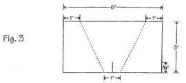
- Tear strength is the force required to start or continue a tear in a fabric under certain conditions, and may be determined as follows. Three specimens are cut in the warp direction and three specimens in the fill direction. Specimens are selected to avoid testing the same group of yarns more than once. Referring to Fig. 3, each specimen is a rectangle, 3" x 6", with the long dimension aligned along a warp yarn for the "warp” test and with the long dimension along a fill yarn for the "fill” test. Using a template, an isosceles trapezoid is marked 3" high with bases of 1" and 4" respectively. A 5/8" long slit is cut in the center of and perpendicular to the 1" trapezoid base.
- the specimen is placed in a tensile tester which is set for a constant rate of extension of 12 ⁇ 0.5 inches per min. With the jaws of the tensile tester 1" apart, the specimen is inserted so that the trapezoidal marks are parallel with the jaws. The slit is positioned half way between the clamps so that the short side of the trapezoid is taut.
- the specimen is torn and the load versus time peaks are recorded. After the specimen is torn, the load values of the five highest peaks are read and the average value of these peaks are recorded as the tear strength value for the specimen. (See Fig. 3)
- Bow and skew are different defects in the dimensional stability of the fabric.
- Bow is a measurement of how much the fill yarns in the central section of the fabric are distorted under load from their original configuration while the skew is a measurement of how much the fill yarns are distorted from one edge of the fabric to the other.
- Light transmission is a measure of the translucency of the composite and may be determined as follows.
- a 4" x 6" specimen is cut from the sample composite and is prepared for testing by heat bleaching it in an air circulating oven at 720° F +/- 10° F for 16 hours (-0, +1 hours).
- the specimen is cooled to room temperature before testing.
- Samples are tested with a visible light-range spectrophotometer, with the specular component included and with a wide area of view. Measurements are taken at 10 nm intervals from 400 to 750 nm in three places on the specimen (two with one face towards the source and one with the opposite face towards the source). The average of the three readings is recorded at each wavelength.
- the average % transmission is calculated in the visible region of the solar spectrum by summing the terms found by multiplying the % transmission at 400, 450, 500, 550, 600, 650, 700 and 750 nm by the following weighted factors respectively: 0.0575, 0.123, 0.148, 0.145, 0.142, 0.143, 0.135, and 0.106.
- Elongation is a measure of the deformation in the direction of load as caused by a tensile force.
- One may measure elongation at a specific load or at tensile break using a static or a dynamic test, depending on the application.
- Percent elongation is usually measured at specific loads, such as prestress or maximum loads.
- the maximum biaxial stress as described in the experimental data below is that load which is 25% of the uniaxial load that would result in rupture of the fabric.
- Uniaxial elongation may be measured as follows. Three specimens are cut in the warp direction and three specimens in the fill direction. For a warp direction specimen, a warp yarn is traced and marked by a line over the surface for at least a length of 16 inches. A second warp yarn, one inch away and parallel to the first (include any partial yarns with the specimen) is similarly traced and marked. In like manner, specimens are traced and marked for generating fill direction specimens. Using a utility knife, the test specimens are then cut along the marked lines for tensile evaluation. Care is taken not to nick the yarns of the test specimen. After all of the specimens are cut, they are laid out on a table to be marked.
- a 10" section is measured approximately 3" in from the end of each specimen.
- the 10" length is marked by pressing the dividers into the fabric, thereby making a small hole.
- the hole is marked with a pen for quick identification.
- one end of the specimen is secured in a weight holding clamp and the other end of the sample in a clamp attached to a stationary rack. This step is repeated with the other specimens.
- a 40# weight is hung on each of the lower clamps. After one hour, the distance is measured between the holes marked on the specimens. The measurements are taken while the specimens remain under load.
- % Uniaxial Elongation L - L o L o x 100 where L is the length between holes after one hour of stressing, and L o is the initial length between holes. The average of the specimens tested for each direction is recorded to the first decimal place.
- Biaxial elongation is measured as follows. As illustrated in the diagram of Fig. 4, the specimen is a cruciform with the arms aligned with the warp and fill directions of the fabric. The overall length along each direction is 580 mm (22.83 inches) and the width of each arm is 160 mm (6.30 inches). The specimen corners are rounded with a 5 mm (0.20 inch) radius. Each arm is slit in half lengthwise from the center biaxial field to the end of the arm and with 50 mm (1.96 inches) slits as shown in Fig. 4. Three specimens are taken from the part of the fabric which is at least 75 mm (2.95 inches) from each selvage.
- the testing machine applies to the specimen a 1:1 load ratio in the warp and fill directions simultaneously.
- the loads in the warp and fill directions are applied from both sides of the specimen so that the center point of the specimen is not changed.
- chucking clamps When mounting the specimen on the testing machine, chucking clamps are fixed to a pre-determined position on the cruciform arms with the warp and fill directions aligned with the testing machine.
- the specimen is fixed so that excessive stress does not affect the specimen and excessive wrinkling does not occur.
- the specimen is clamped so that uniform force is applied in the warp and fill directions during the test and tightly enough that slipping does not occur between the specimen and the clamps.
- Strain generated in the biaxial field at the center of the specimen is measured in the warp and fill directions simultaneously with the load.
- the distance between the initial extension measurement points is between 20 mm (0.79 inch) and 80 mm (3.15 inches).
- Fig. 5 is an example of a graph showing the stress strain data for the first and third loading cycles. Comparative values for elongation (denoted as strain on the graph) may be read from these graphs.
- the customary points of comparison are the strain at the estimated installation load (39 pli on the first loading cycle), the strain at the prestress load after removing material hysteresis (11 pli on the third loading cycle), and the strain at the maximum biaxial test load after removing material hysteresis. Values for these three customary points of comparison are set forth in the tables.
- Tables Ia, b, and c illustrate the problems associated with prior-art plain-woven fiberglass fabrics which may have an appropriate overall tensile strength but are limited in overall light transmission and lack appropriate elongations under biaxial loads even if the yarns are deployed at varying warp and fill counts. As a result, it has been difficult or impossible to avoid negative warp elongation.
- the data listed in Table IIa show the advantageous aspects of a mock leno weave style composite including the composite's desirable translucency and mechanical properties.
- the data show relatively high tensile breaking strength as well as positive ( i.e. , non-negative) biaxial elongations in the warp and fill directions.
- these composites have a translucency of 23.4-28.8%, and when subjected to 1:1 biaxial loads up to 25% of the uniaxial tensile breaking strength of the fabric, the composites exhibit biaxial elongation values of 0.04-0.42% in the warp direction and 0.70-3.17% in the fill direction.
- the composites exhibit excellent translucency properties and will mechanically perform well in tensioned structures.
- the mock leno woven reinforcement of the invention forms an advantageously large size gap or window when under tension thereby increasing the translucency.
- the elongation characteristics of this preferred type of fabric which is advantageously superior to that of a plain woven fabric is apparently due to its hybrid structural mixture of plain woven and satin-woven styles.
- an improved light transmission nearly a third higher than in presently available PTFE/fiberglass architectural fabrics has been achieved by use of mock leno weave reinforced composite while exhibiting non-negative, biaxial elongation properties in both the warp or the fill direction.
- Table IIb shows data for plain woven composites according to the invention.
- Composites NSP A96024a-c of Table IIb are embodiments where the yarn count in the fill direction is equal to or greater than 1.25 times the yarn count in the warp direction. These composites have translucency values of 21.6-25%, and when subjected to 1:1 biaxial installation, prestress, and maximum loads up to 25% of the uniaxial tensile breaking strength of the fabric, the composites exhibit biaxial elongation values of 0.0-0.15% in the warp direction and of 2.5-8.6% in the fill direction.
- Composite NSP A96024d in Table IIb has a fabric yarn construction of 12 x 14 (w x f), and thus the yarn count in the fill direction is less than 1.25 times the yarn count in the warp direction.
- the resulting composite exhibits negative biaxial elongation values when subjected to certain loads. As explained above, the negative biaxial elongation values make such composite constructions undesirable for use as load-bearing structures.
- the preferred embodiment of the invention having at least about 23% translucency was prepared to meet certain target tensile or breaking strengths in warp (w) and fill (f) directions.
- the biaxial elongation was not to exhibit negative stress values. Accordingly, the elongation of warp (BEW) is greater than zero while elongation of fill (BEF) is greater than BEW.
- an 11 osy (ounce per square yard) fiberglass fabric coating substrate was woven.
- the substrate was a 6 x 6 mock leno weave consisting of B150 2/4 yarns in both warp and fill direction. The count was 19 x 16.5 yarns/inch in the warp and fill direction, respectively.
- This substrate designated CHEMFAB style NSP A96053 (shown in Table IIa), was heat-cleaned to remove residual sizing. The substrate was then relubricated by applying a methylphenyl silicone oil (ET-4327 obtained from Dow Corning as an aqueous emulsion, 35% solids).
- the oil was applied to the substrate at 4% by weight by dipping and drying in a two zone coating tower with a drying zone temperature of 200-300° F and a sintering zone temperature set at 550°F. In the first coating only the yarns in the substrate were coated, while the windows remained open.
- a second coating, totaling approximately 7.5 osy was applied by dipping the substrate in an aqueous dispersion of PTFE (T313A obtained from Dupont and applied at 53% solids).
- the coating was dried and sintered in a two-zone coating tower with drying temperatures of 350°F and sintering zone temperatures 680°F.
- a third coating totaling approximately 15 osy, was applied from a formulation of T313A, with an additional 4% (by weight based on PTFE solids) of a surfactant (Triton X-100 from Union Carbide).
- the coating was applied at 56.3% in several passes, by dipping, drying and baking or sintering in a two-zone tower.
- the drying zone temperature was 350°F.
- the sintering zone temperature was 680°F on passes 1, 4 and 5; and it was 600°F on passes 2 and 3.
- the composite was finished with a topcoat using PFA dispersion (TE-9946 obtained from DuPont and applied at 38% solids).
- the topcoat was applied at about 1.5 osy by dipping, drying and sintering in a two-zone tower. The drying temperature was 350°F, and the sintering temperature was 680°F.
- Fig. 5 shows a modulus curve for the composite NSP A96053.
- Fig. 5 shows curves for the first and third loading cycles. The curve for the second loading cycle falls within these first and third loading cycle curves. These curves represent the biaxial elongation of one of the three NSP A96053 specimens tested.
- PROPERTY NSP A96012a NSP A96012b NSP A96021 yarn construction (w x f) B150 4/2 x B150 4/3 B150 4/2 x B150 4/3 B150 4/2 x B150 4/3 greige count (w x f) - number/inch 17 x 13.5 17 x 12.5 16 x 13 gauge - mils (thickness) 29.3 30.6 28.6 tensile breaking strength (w x f) - pli 747 x 722 720 x 733 701 x 735 tear strength (w x f) - lbs (trapezoid) 59 x 101 63 x 95 63 113 bow - % 0.5 0.1 2.3 skew - % 0.3 0.1 3.1 light transmission - % 20.8 21.7 24.2 open area - % 23.7 25.6 2
Priority Applications (4)
| Application Number | Priority Date | Filing Date | Title |
|---|---|---|---|
| US08/733,579 US5759924A (en) | 1996-10-18 | 1996-10-18 | Translucent polymeric composite for use in an architectural load-bearing structure |
| EP19970307037 EP0905302B1 (fr) | 1996-10-18 | 1997-09-09 | Matériau composite polymère utile dans une structure porteuse architecturale |
| DE69728874T DE69728874T2 (de) | 1997-09-09 | 1997-09-09 | Lichtdurchlässiger polymerischer Verbundwerkstoff zur Verwendung in einer architektonischen tragenden Struktur |
| AT97307037T ATE265569T1 (de) | 1997-09-09 | 1997-09-09 | Lichtdurchlässiger polymerischer verbundwerkstoff zur verwendung in einer architektonischen tragenden struktur |
Applications Claiming Priority (2)
| Application Number | Priority Date | Filing Date | Title |
|---|---|---|---|
| US08/733,579 US5759924A (en) | 1996-10-18 | 1996-10-18 | Translucent polymeric composite for use in an architectural load-bearing structure |
| EP19970307037 EP0905302B1 (fr) | 1996-10-18 | 1997-09-09 | Matériau composite polymère utile dans une structure porteuse architecturale |
Publications (2)
| Publication Number | Publication Date |
|---|---|
| EP0905302A1 true EP0905302A1 (fr) | 1999-03-31 |
| EP0905302B1 EP0905302B1 (fr) | 2004-04-28 |
Family
ID=26147598
Family Applications (1)
| Application Number | Title | Priority Date | Filing Date |
|---|---|---|---|
| EP19970307037 Expired - Lifetime EP0905302B1 (fr) | 1996-10-18 | 1997-09-09 | Matériau composite polymère utile dans une structure porteuse architecturale |
Country Status (2)
| Country | Link |
|---|---|
| US (1) | US5759924A (fr) |
| EP (1) | EP0905302B1 (fr) |
Cited By (3)
| Publication number | Priority date | Publication date | Assignee | Title |
|---|---|---|---|---|
| WO2002018136A2 (fr) * | 2000-09-01 | 2002-03-07 | Chemfab Corporation | Composites polymeriques de chlorotrifluoroethylene utilises dans des structures porteuses architecturales |
| US10751973B2 (en) | 2016-03-21 | 2020-08-25 | Saint-Gobain Performance Plastics Corporation | Architectural membrane |
| US11768193B2 (en) | 2019-12-20 | 2023-09-26 | The Research Foundation For The State University Of New York | System and method for characterizing the equibiaxial compressive strength of 2D woven composites |
Families Citing this family (19)
| Publication number | Priority date | Publication date | Assignee | Title |
|---|---|---|---|---|
| EP0767052A1 (fr) * | 1995-10-02 | 1997-04-09 | Sarna Patent- Und Lizenz-Ag | Feuille d'étanchéité en matière synthétique |
| US6419981B1 (en) | 1998-03-03 | 2002-07-16 | Ppg Industries Ohio, Inc. | Impregnated glass fiber strands and products including the same |
| US8105690B2 (en) | 1998-03-03 | 2012-01-31 | Ppg Industries Ohio, Inc | Fiber product coated with particles to adjust the friction of the coating and the interfilament bonding |
| US6593255B1 (en) | 1998-03-03 | 2003-07-15 | Ppg Industries Ohio, Inc. | Impregnated glass fiber strands and products including the same |
| FR2780990B1 (fr) * | 1998-07-07 | 2000-08-18 | Tissus Tech De Trevoux | Procede pour l'obtention d'un tissu enduit extensible et nouveau type de tissu obtenu par la mise en oeuvre d'un tel procede |
| US6919122B2 (en) * | 1999-07-08 | 2005-07-19 | Saint-Gobain Performance Plastics Corporation | Flexible composites with integral flights for use in high-temperature food processing equipment and methods for producing the same |
| CN1413274A (zh) * | 1999-12-24 | 2003-04-23 | 约翰·堡格 | 带及其生产方法 |
| US7927684B2 (en) * | 2000-01-19 | 2011-04-19 | Saint-Gobain Performance Plastics Corporation | Low coefficient of friction polymer film |
| US8062746B2 (en) * | 2003-03-10 | 2011-11-22 | Ppg Industries, Inc. | Resin compatible yarn binder and uses thereof |
| US7338574B2 (en) * | 2003-05-13 | 2008-03-04 | Saint-Gobain Performance Plastics Corporation | Multilayer composite and method of making same |
| US7326661B2 (en) * | 2004-05-14 | 2008-02-05 | Chilewich L.L.C. | Fiberglass fabric flooring system |
| US7005613B1 (en) | 2004-12-17 | 2006-02-28 | Saint-Gobain Performance Plastics Corporation | Method for cleaning ovens and merchandised article relating thereto |
| US20060134391A1 (en) * | 2004-12-17 | 2006-06-22 | Saint-Gobain Performance Plastics Corporation | Methods for making arts and crafts articles and merchandised articles relating thereto |
| US8349747B2 (en) | 2005-08-02 | 2013-01-08 | W. L. Gore & Associates, Inc. | High seam strength architectural fabric |
| US7501356B2 (en) * | 2005-08-02 | 2009-03-10 | Gore Enterprise Holdings, Inc. | Architectural fabric |
| US8187733B2 (en) | 2005-08-02 | 2012-05-29 | W. L. Gore & Associates, Inc. | Architectural fabric |
| US9527250B2 (en) * | 2011-12-19 | 2016-12-27 | Toyota Motor Engineering & Manufacturing North America, Inc. | Methods, apparatus and systems for reducing warpage in polymers with continuous fibers |
| US10450141B2 (en) | 2016-11-29 | 2019-10-22 | Saint-Gobain Performance Plastics Corporation | Composite belt profile |
| DE102017215369A1 (de) * | 2017-09-01 | 2019-03-07 | Benecke-Kaliko Ag | Lichtdurchlässige Mehrschichtverbundfolie |
Citations (8)
| Publication number | Priority date | Publication date | Assignee | Title |
|---|---|---|---|---|
| EP0164278A1 (fr) * | 1984-04-13 | 1985-12-11 | Chemical Fabrics Corporation | Matériaux composites flexibles résistant à l'usure et contenant des polymères fluorés et méthode pour leur fabrication |
| US4594286A (en) * | 1985-05-07 | 1986-06-10 | Graniteville Company | Coated fabric |
| EP0327047A2 (fr) * | 1988-02-04 | 1989-08-09 | Hoechst Aktiengesellschaft | Compositions pour revêtements avec des fluoropolymères |
| WO1989012135A1 (fr) * | 1988-06-04 | 1989-12-14 | Scapa Group Plc | Matieres textiles a revetement |
| DE3832828A1 (de) * | 1988-09-28 | 1990-04-12 | Hoechst Ag | Ueberzugszusammensetzung aus fluorpolymeren |
| WO1992009429A1 (fr) * | 1990-11-23 | 1992-06-11 | Chemfab Corporation | Materiaux composites ameliores a usage structural architectural |
| JPH04300363A (ja) * | 1991-03-27 | 1992-10-23 | Nitto Denko Corp | 膜構造材料および二重膜屋根 |
| DE29620579U1 (de) * | 1996-12-12 | 1997-06-12 | Fitz Johannes | Textiler Membranwerkstoff mit hoher Lichtdurchlässigkeit |
Family Cites Families (1)
| Publication number | Priority date | Publication date | Assignee | Title |
|---|---|---|---|---|
| DE3246803A1 (de) * | 1982-12-17 | 1984-06-20 | Messerschmitt-Bölkow-Blohm GmbH, 8000 München | Verfahren zum herstellen von bauteilen aus lagen von faserverstaerktem kunststoff |
-
1996
- 1996-10-18 US US08/733,579 patent/US5759924A/en not_active Expired - Lifetime
-
1997
- 1997-09-09 EP EP19970307037 patent/EP0905302B1/fr not_active Expired - Lifetime
Patent Citations (8)
| Publication number | Priority date | Publication date | Assignee | Title |
|---|---|---|---|---|
| EP0164278A1 (fr) * | 1984-04-13 | 1985-12-11 | Chemical Fabrics Corporation | Matériaux composites flexibles résistant à l'usure et contenant des polymères fluorés et méthode pour leur fabrication |
| US4594286A (en) * | 1985-05-07 | 1986-06-10 | Graniteville Company | Coated fabric |
| EP0327047A2 (fr) * | 1988-02-04 | 1989-08-09 | Hoechst Aktiengesellschaft | Compositions pour revêtements avec des fluoropolymères |
| WO1989012135A1 (fr) * | 1988-06-04 | 1989-12-14 | Scapa Group Plc | Matieres textiles a revetement |
| DE3832828A1 (de) * | 1988-09-28 | 1990-04-12 | Hoechst Ag | Ueberzugszusammensetzung aus fluorpolymeren |
| WO1992009429A1 (fr) * | 1990-11-23 | 1992-06-11 | Chemfab Corporation | Materiaux composites ameliores a usage structural architectural |
| JPH04300363A (ja) * | 1991-03-27 | 1992-10-23 | Nitto Denko Corp | 膜構造材料および二重膜屋根 |
| DE29620579U1 (de) * | 1996-12-12 | 1997-06-12 | Fitz Johannes | Textiler Membranwerkstoff mit hoher Lichtdurchlässigkeit |
Non-Patent Citations (3)
| Title |
|---|
| "Hostaflon-beschichtete Glasgewebe", CHEMIEFASERN/TEXTILINDUSTRIE, vol. 40, no. 6, June 1990 (1990-06-01), FRANKFURT/MAIN DE, pages t86 - t88, XP000138251 * |
| DATABASE WPI Section Ch Week 9250, Derwent World Patents Index; Class A18, AN 92-409544, XP002055161 * |
| H. FITZ: "Neue Wege im Einsatz von Fluorkunststoffen für transparente Überdachungen", TECHNISCHE RUNDSCHAU, no. 51/52, December 1983 (1983-12-01), BERN CH, pages 10 - 13, XP002055160 * |
Cited By (4)
| Publication number | Priority date | Publication date | Assignee | Title |
|---|---|---|---|---|
| WO2002018136A2 (fr) * | 2000-09-01 | 2002-03-07 | Chemfab Corporation | Composites polymeriques de chlorotrifluoroethylene utilises dans des structures porteuses architecturales |
| WO2002018136A3 (fr) * | 2000-09-01 | 2002-06-06 | Chemfab Corp | Composites polymeriques de chlorotrifluoroethylene utilises dans des structures porteuses architecturales |
| US10751973B2 (en) | 2016-03-21 | 2020-08-25 | Saint-Gobain Performance Plastics Corporation | Architectural membrane |
| US11768193B2 (en) | 2019-12-20 | 2023-09-26 | The Research Foundation For The State University Of New York | System and method for characterizing the equibiaxial compressive strength of 2D woven composites |
Also Published As
| Publication number | Publication date |
|---|---|
| US5759924A (en) | 1998-06-02 |
| EP0905302B1 (fr) | 2004-04-28 |
Similar Documents
| Publication | Publication Date | Title |
|---|---|---|
| US5759924A (en) | Translucent polymeric composite for use in an architectural load-bearing structure | |
| Pan | Analysis of woven fabric strengths: prediction of fabric strength under uniaxial and biaxial extensions | |
| JP4141686B2 (ja) | 高強度ポリエチレン繊維およびその利用 | |
| Zhu et al. | Dynamic tensile testing of fabric–cement composites | |
| Hamburger | The industrial application of the stress-strain relationship | |
| US20070072502A1 (en) | Non-coated fabric for outdoor applications | |
| JPS6237154B2 (fr) | ||
| Li et al. | Effects of natural ageing on mechanical properties of PVDF-coated fabrics | |
| JP2021195755A (ja) | 膜天井用シート及び該膜天井用シートを用いた膜天井 | |
| WO2001096695A1 (fr) | Membrane composite pour la regulation des environnements interieurs | |
| JP3393787B2 (ja) | 荷重支持構造体に用いる半透明ポリマー複合体およびその製造方法 | |
| Uhlemann et al. | Stiffness parameters for architectural fabrics: an analysis of two determination procedures | |
| Gilewicz et al. | Change in structural and thermal properties of textile fabric packages containing basalt fibres after fatigue bending loading | |
| DE112020005283T5 (de) | Verfahren zur Oberflächenaktivierung in Nanotiefe auf der Basis einer PTFE-Membran | |
| KR200296423Y1 (ko) | 텍스타일 지오그리드 | |
| Uhlemann et al. | Comparison of stiffness properties of common coated fabrics | |
| DE69728874T2 (de) | Lichtdurchlässiger polymerischer Verbundwerkstoff zur Verwendung in einer architektonischen tragenden Struktur | |
| JP4984314B2 (ja) | 繊維束多軸組布及びその製造方法 | |
| Remy et al. | High performance textile reinforced cements: tensile hardening behaviour and modeling | |
| Ghosh et al. | A review on mechanical characterization of PVC coated fabrics | |
| Pandita et al. | Matrix dominated failure in plain weave fabric composites subjected to tension-tension fatigue loads | |
| Zerdzicki et al. | Strength parameters of polyester reinforced PVC coated fabric after short term creep loading in biaxial mode | |
| Norris et al. | The weathering of glass-reinforced polyesters under stress—short term behaviour | |
| JP7466889B2 (ja) | 複合シート | |
| Asadi et al. | Water-induced ageing modification factor for PTFE-coated glass fibre fabric |
Legal Events
| Date | Code | Title | Description |
|---|---|---|---|
| PUAI | Public reference made under article 153(3) epc to a published international application that has entered the european phase |
Free format text: ORIGINAL CODE: 0009012 |
|
| AK | Designated contracting states |
Kind code of ref document: A1 Designated state(s): AT BE CH DE DK ES FI FR GB GR IE IT LI LU MC NL PT SE |
|
| AX | Request for extension of the european patent |
Free format text: AL;LT;LV;RO;SI |
|
| 17P | Request for examination filed |
Effective date: 19990930 |
|
| AKX | Designation fees paid |
Free format text: AT BE CH DE DK ES FI FR GB GR IE IT LI LU MC NL PT SE |
|
| 17Q | First examination report despatched |
Effective date: 20020502 |
|
| GRAP | Despatch of communication of intention to grant a patent |
Free format text: ORIGINAL CODE: EPIDOSNIGR1 |
|
| RAP1 | Party data changed (applicant data changed or rights of an application transferred) |
Owner name: SAINT-GOBAIN PERFORMANCE PLASTICS CORPORATION |
|
| GRAS | Grant fee paid |
Free format text: ORIGINAL CODE: EPIDOSNIGR3 |
|
| GRAA | (expected) grant |
Free format text: ORIGINAL CODE: 0009210 |
|
| AK | Designated contracting states |
Kind code of ref document: B1 Designated state(s): AT BE CH DE DK ES FI FR GB GR IE IT LI LU MC NL PT SE |
|
| PG25 | Lapsed in a contracting state [announced via postgrant information from national office to epo] |
Ref country code: NL Free format text: LAPSE BECAUSE OF FAILURE TO SUBMIT A TRANSLATION OF THE DESCRIPTION OR TO PAY THE FEE WITHIN THE PRESCRIBED TIME-LIMIT Effective date: 20040428 Ref country code: LI Free format text: LAPSE BECAUSE OF FAILURE TO SUBMIT A TRANSLATION OF THE DESCRIPTION OR TO PAY THE FEE WITHIN THE PRESCRIBED TIME-LIMIT Effective date: 20040428 Ref country code: IT Free format text: LAPSE BECAUSE OF FAILURE TO SUBMIT A TRANSLATION OF THE DESCRIPTION OR TO PAY THE FEE WITHIN THE PRESCRIBED TIME-LIMIT;WARNING: LAPSES OF ITALIAN PATENTS WITH EFFECTIVE DATE BEFORE 2007 MAY HAVE OCCURRED AT ANY TIME BEFORE 2007. THE CORRECT EFFECTIVE DATE MAY BE DIFFERENT FROM THE ONE RECORDED. Effective date: 20040428 Ref country code: FI Free format text: LAPSE BECAUSE OF FAILURE TO SUBMIT A TRANSLATION OF THE DESCRIPTION OR TO PAY THE FEE WITHIN THE PRESCRIBED TIME-LIMIT Effective date: 20040428 Ref country code: CH Free format text: LAPSE BECAUSE OF FAILURE TO SUBMIT A TRANSLATION OF THE DESCRIPTION OR TO PAY THE FEE WITHIN THE PRESCRIBED TIME-LIMIT Effective date: 20040428 Ref country code: BE Free format text: LAPSE BECAUSE OF FAILURE TO SUBMIT A TRANSLATION OF THE DESCRIPTION OR TO PAY THE FEE WITHIN THE PRESCRIBED TIME-LIMIT Effective date: 20040428 Ref country code: AT Free format text: LAPSE BECAUSE OF FAILURE TO SUBMIT A TRANSLATION OF THE DESCRIPTION OR TO PAY THE FEE WITHIN THE PRESCRIBED TIME-LIMIT Effective date: 20040428 |
|
| REG | Reference to a national code |
Ref country code: GB Ref legal event code: FG4D |
|
| REG | Reference to a national code |
Ref country code: CH Ref legal event code: EP |
|
| REG | Reference to a national code |
Ref country code: IE Ref legal event code: FG4D |
|
| REF | Corresponds to: |
Ref document number: 69728874 Country of ref document: DE Date of ref document: 20040603 Kind code of ref document: P |
|
| PG25 | Lapsed in a contracting state [announced via postgrant information from national office to epo] |
Ref country code: SE Free format text: LAPSE BECAUSE OF FAILURE TO SUBMIT A TRANSLATION OF THE DESCRIPTION OR TO PAY THE FEE WITHIN THE PRESCRIBED TIME-LIMIT Effective date: 20040728 Ref country code: GR Free format text: LAPSE BECAUSE OF FAILURE TO SUBMIT A TRANSLATION OF THE DESCRIPTION OR TO PAY THE FEE WITHIN THE PRESCRIBED TIME-LIMIT Effective date: 20040728 Ref country code: DK Free format text: LAPSE BECAUSE OF FAILURE TO SUBMIT A TRANSLATION OF THE DESCRIPTION OR TO PAY THE FEE WITHIN THE PRESCRIBED TIME-LIMIT Effective date: 20040728 |
|
| PG25 | Lapsed in a contracting state [announced via postgrant information from national office to epo] |
Ref country code: ES Free format text: LAPSE BECAUSE OF FAILURE TO SUBMIT A TRANSLATION OF THE DESCRIPTION OR TO PAY THE FEE WITHIN THE PRESCRIBED TIME-LIMIT Effective date: 20040808 |
|
| PG25 | Lapsed in a contracting state [announced via postgrant information from national office to epo] |
Ref country code: LU Free format text: LAPSE BECAUSE OF NON-PAYMENT OF DUE FEES Effective date: 20040909 Ref country code: IE Free format text: LAPSE BECAUSE OF NON-PAYMENT OF DUE FEES Effective date: 20040909 |
|
| PG25 | Lapsed in a contracting state [announced via postgrant information from national office to epo] |
Ref country code: MC Free format text: LAPSE BECAUSE OF NON-PAYMENT OF DUE FEES Effective date: 20040930 |
|
| NLV1 | Nl: lapsed or annulled due to failure to fulfill the requirements of art. 29p and 29m of the patents act | ||
| REG | Reference to a national code |
Ref country code: CH Ref legal event code: PL |
|
| ET | Fr: translation filed | ||
| PLBE | No opposition filed within time limit |
Free format text: ORIGINAL CODE: 0009261 |
|
| STAA | Information on the status of an ep patent application or granted ep patent |
Free format text: STATUS: NO OPPOSITION FILED WITHIN TIME LIMIT |
|
| 26N | No opposition filed |
Effective date: 20050131 |
|
| REG | Reference to a national code |
Ref country code: IE Ref legal event code: MM4A |
|
| PG25 | Lapsed in a contracting state [announced via postgrant information from national office to epo] |
Ref country code: PT Free format text: LAPSE BECAUSE OF NON-PAYMENT OF DUE FEES Effective date: 20040928 |
|
| PGFP | Annual fee paid to national office [announced via postgrant information from national office to epo] |
Ref country code: DE Payment date: 20100929 Year of fee payment: 14 |
|
| PGFP | Annual fee paid to national office [announced via postgrant information from national office to epo] |
Ref country code: GB Payment date: 20110926 Year of fee payment: 15 Ref country code: FR Payment date: 20111005 Year of fee payment: 15 |
|
| GBPC | Gb: european patent ceased through non-payment of renewal fee |
Effective date: 20120909 |
|
| REG | Reference to a national code |
Ref country code: FR Ref legal event code: ST Effective date: 20130531 |
|
| PG25 | Lapsed in a contracting state [announced via postgrant information from national office to epo] |
Ref country code: DE Free format text: LAPSE BECAUSE OF NON-PAYMENT OF DUE FEES Effective date: 20130403 Ref country code: GB Free format text: LAPSE BECAUSE OF NON-PAYMENT OF DUE FEES Effective date: 20120909 |
|
| PG25 | Lapsed in a contracting state [announced via postgrant information from national office to epo] |
Ref country code: FR Free format text: LAPSE BECAUSE OF NON-PAYMENT OF DUE FEES Effective date: 20121001 |
|
| REG | Reference to a national code |
Ref country code: DE Ref legal event code: R119 Ref document number: 69728874 Country of ref document: DE Effective date: 20130403 |