EP0905149B1 - Procédé pour éliminer des matières volatiles d' une composition polymère - Google Patents
Procédé pour éliminer des matières volatiles d' une composition polymère Download PDFInfo
- Publication number
- EP0905149B1 EP0905149B1 EP98118141A EP98118141A EP0905149B1 EP 0905149 B1 EP0905149 B1 EP 0905149B1 EP 98118141 A EP98118141 A EP 98118141A EP 98118141 A EP98118141 A EP 98118141A EP 0905149 B1 EP0905149 B1 EP 0905149B1
- Authority
- EP
- European Patent Office
- Prior art keywords
- polymer composition
- blowing
- blowing aid
- volatile materials
- polymer
- Prior art date
- Legal status (The legal status is an assumption and is not a legal conclusion. Google has not performed a legal analysis and makes no representation as to the accuracy of the status listed.)
- Expired - Lifetime
Links
Images
Classifications
-
- C—CHEMISTRY; METALLURGY
- C08—ORGANIC MACROMOLECULAR COMPOUNDS; THEIR PREPARATION OR CHEMICAL WORKING-UP; COMPOSITIONS BASED THEREON
- C08F—MACROMOLECULAR COMPOUNDS OBTAINED BY REACTIONS ONLY INVOLVING CARBON-TO-CARBON UNSATURATED BONDS
- C08F6/00—Post-polymerisation treatments
- C08F6/06—Treatment of polymer solutions
- C08F6/10—Removal of volatile materials, e.g. solvents
-
- C—CHEMISTRY; METALLURGY
- C08—ORGANIC MACROMOLECULAR COMPOUNDS; THEIR PREPARATION OR CHEMICAL WORKING-UP; COMPOSITIONS BASED THEREON
- C08F—MACROMOLECULAR COMPOUNDS OBTAINED BY REACTIONS ONLY INVOLVING CARBON-TO-CARBON UNSATURATED BONDS
- C08F6/00—Post-polymerisation treatments
- C08F6/26—Treatment of polymers prepared in bulk also solid polymers or polymer melts
- C08F6/28—Purification
-
- C—CHEMISTRY; METALLURGY
- C08—ORGANIC MACROMOLECULAR COMPOUNDS; THEIR PREPARATION OR CHEMICAL WORKING-UP; COMPOSITIONS BASED THEREON
- C08F—MACROMOLECULAR COMPOUNDS OBTAINED BY REACTIONS ONLY INVOLVING CARBON-TO-CARBON UNSATURATED BONDS
- C08F6/00—Post-polymerisation treatments
- C08F6/001—Removal of residual monomers by physical means
- C08F6/005—Removal of residual monomers by physical means from solid polymers
Definitions
- the present invention relates to a method for removing volatile materials contained in a polymer composition. More specifically, the present invention relates to a method for providing a product reduced in volatile materials by adding a blowing aid to a polymer composition containing unreacted monomer, solvent, etc., to remove volatile materials together with the blowing aid.
- removal of volatile materials is generally carried out by heating the polymer solution, under reduced pressure, to a temperature higher than the temperature at which the volatile materials vaporize.
- the conventional techniques can, for example, reduce residual styrene and residual solvent in polystyrene easily to 500 to 1,000 ppm in total, to reduce them to 150 ppm or less, simple heating cannot attain the removal of volatile materials, and various contrivances are needed.
- a method in which water is injected into a melted polymer, and then flushing with water is carried out under reduced pressure, to remove residual volatiles together with the water.
- US-A-3 773 740 discloses a technique in which water is added to a polymer melt, so that 0.5 to 2.75% by weight of water is injected, and thereafter the pressure of the melt is reduced to 20 to 40 Torr, to flush with the water all at once, thereby reducing the amount of residual aromatic monomer to 0.3% by weight.
- This technique cannot carry out a high degree of removal of volatile materials to the level demanded currently.
- a method for solving this problem for example, a method is disclosed in US-A-5 380 822, wherein residual monomer, oligomers (e.g. dimer and trimer), and solvent are reduced to 500 ppm or less, and preferably 150 ppm or less, in at least one polymer, particularly a polymer of a vinyl aromatic monomer, such as a polystyrene, or in a blend composition of a polymer of a vinyl aromatic monomer with a polyphenylene oxide.
- water in an amount equal to or more than the amount of residual volatiles, i.e.
- the polymer or polymer composition in an amount of 1% by weight or more, is injected into the polymer or polymer composition, whose pressure is kept at 500 to 1,500 psi at 200 to 270 °C, which polymer or polymer composition is then introduced into a flash chamber devolatilizer having a pressure-reduced zone, where the pressure is kept at less than 5 Torr, and preferably at less than 3 Torr, thereby allowing the polymer to pass through distributor tray means, to remove volatile materials.
- a flash chamber devolatilizer having a pressure-reduced zone, where the pressure is kept at less than 5 Torr, and preferably at less than 3 Torr, thereby allowing the polymer to pass through distributor tray means, to remove volatile materials.
- the pressure in the devolatilizing tank in order to bring residual volatiles to 150 ppm or less, it is required to keep the pressure in the devolatilizing tank at less than 5 Torr, and preferably at less than 3 Torr, to expose water and monomer in the poly
- an ejector is placed upstream of the condenser, to keep the pressure in the condenser at 5 Torr or more, so that water may be prevented from freezing.
- a method is thus conceivable in which, in order to remove volatiles, the temperature of the polymer is elevated, with the pressure in a devolatilizing tank being kept at 10 mmHg or more.
- the temperature of the polymer composition is elevated, the residual monomer is polymerized in a preheater or the like, to increase the amount of low-molecular-weight polymers in the polymers, leading to a drop in the heat resistance of molded products, adhesion of oily material to molds at the time of molding, and deterioration of the hue of the polymer, in some cases.
- thermal modification takes place, to cause the polymer to be discolored or deteriorated.
- the formation of decomposition gases due to the decomposition of the polymer exceeds the effect for decreasing volatile components, and therefore it cannot be said that the method is a preferable one.
- An object of the present invention is to provide a method for giving a polymer composition having residual volatile materials in very small amounts, by removing volatile materials continuously with high efficiency, to solve the above problems.
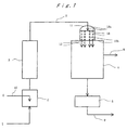
- Fig. 1 is an illustrative diagram showing one embodiment of apparatus of the present invention.
- the inventors of the present invention having intensively investigated to solve the above problems, have found that it is important to disperse and mix uniformly a melted polymer composition, and, as a blowing aid, water, an aliphatic hydrocarbon compound containing at least one hydroxyl group or carbonyl group and having a boiling point lower than unreacted monomer or residual solvent, or a mixture of water with such an aliphatic hydrocarbon compound, and to remove volatile materials while blowing stably the melted polymer composition; and that a polymer having reduced amounts of residual volatile materials can be obtained by satisfying these conditions simultaneously.
- the present invention has been completed based on these findings.
- the volatile materials to be removed mean volatile components in a polymer liquid composition containing a polymer, and examples include unreacted monomers used in the production of the polymer, organic solvents used for the production of the polymer, such as aliphatic hydrocarbons (e.g. hexane, heptane, octane, and decane), benzene, toluene, ethylbenzene, xylene, cumene, and other alkylbenzenes, halogenated hydrocarbons, halogenated aromatic hydrocarbons, nitrile compounds, amine compounds, and the like, which organic solvents can be used as polymerization solvents industrially, and oligomers (e.g. dimers and trimers of monomers).
- organic solvents e.g. hexane, heptane, octane, and decane
- benzene toluene
- ethylbenzene ethyl
- the polymer composition for use in the present invention refers to a polymer containing at least small amounts or trace amounts of volatile materials in a polymer.
- the polymer used in the present invention refers to a thermoplastic polymer, and, specifically, a polyethylene, an ethylene/ ⁇ -olefin copolymer, a polystyrene, HIPS, ABS, a styrene/acrylic acid copolymer, a styrene/methacrylate copolymer, a polypropylene, a polyphenylene ether, a polycarbonate, a polyvinyl chloride, a polyetherimide, a polyamide, a polyester, a silicone polymer, such as a polysiloxane; a polybutadiene, a polyisoprene, an ethylene/propylene rubber, an ethylene/propylene/diene rubber, a butadiene/styrene rubber, and the like can be mentioned.
- the present invention is characterized in that a polymer composition whose content of volatile materials is low can be purified further, and the content of volatile materials of the polymer composition to be processed is not particularly limited, but it is generally 2% by weight or less, preferably 0.01 to 2% by weight, and more preferably 0.05 to 1.5% by weight.
- Fig. 1 is an illustrative diagram showing one mode of the present invention.
- a polystyrene as an example, arbitrarily, the description is made based on Fig. 1.
- the polystyrene is only an example, and the present invention is not limited to it.
- the addition nozzle apparatus comprises at least one opening section directed to the direction opposite to the direction of the flow of the melted polystyrene to allow the blowing aid to be discharged and added to continuously in the direction opposite to that of the flow of the melted polystylene.
- the polystyrene composition When volatile materials amount to over 2% by weight, the polystyrene composition is previously supplied to a devolatilizing tank (not shown), before being supplied to the below-mentioned static mixing apparatus, and the polystyrene composition is processed with the conditions of the temperature and the pressure of the devolatilizing tank controlled, so that the polystyrene polymer composition may contain volatile materials in an amount of 2% by weight or less.
- a blowing aid 6 selected from the group consisting of water, aliphatic hydrocarbon compounds containing at least one hydroxyl group or carbonyl group, and having a boiling point lower than those of unreacted monomer and solvent, and a mixture thereof, in an amount of less than 10% by weight based on the said polystyrene composition, is supplied to the addition nozzle apparatus 2, through a line 10, and it is added by discharging it in a direction opposite to the direction of the flow of the said melted polystyrene.
- the term "the introduction of the blowing aid in a direction opposite to the direction of the flow of the polymer composition” includes, besides the case in which the blowing aid is introduced in a direction utterly opposite to the direction of the flow, the case in which the blowing aid is introduced in a direction opposite to the direction of the flow with a prescribed angle made with the direction of the flow.
- the angle is not limited, but it is preferably in the range of ⁇ 45°, and more preferably ⁇ 5°, with the direction utterly opposite to the direction of the flow of the polymer composition being 0°.
- the said blowing aid when added in the direction of the flow of the said polystyrene composition oppositely to the method of the present invention, the said blowing aid is destined to be supplied to one point of the said static mixer positioned downstream. Therefore the blowing aid will not be dispersed or mixed uniformly, thereby lowering the mixing performance, unpreferably.
- the blowing aid added in this way is introduced into the static mixing apparatus 3, connected just after the addition nozzle apparatus 2, in such a manner that the said blowing aid is out of contact with the pipe walls of the pipeline provided for the said addition nozzle apparatus and the pipeline connecting the said addition nozzle apparatus and the said static mixing apparatus, until the said blowing aid reaches the said static mixing apparatus provided for connecting.
- the said blowing aid comes in contact with the pipeline provided for the said addition nozzle apparatus and the pipeline connecting the said addition nozzle apparatus and the said static mixing apparatus, before the said blowing aid reaches the said static mixer 3, since the flow velocity of the said polystyrene composition at the pipe wall section is very low, a thick layer of the blowing aid is formed, to lower the mixing performance of the static mixer. When there is no contact with the walls of the pipeline, a thick layer is not formed, and the performance of the static mixer is not lowered. Keeping the blowing aid thus out of contact with the walls of the pipelines can be realized by arranging the said addition nozzle near the central part of the flow of the said polystyrene composition, so that the said addition nozzle may be out of contact with the pipeline.
- the blowing aid is added in an amount exceeding a certain limit for the polymer composition, the increase in the effect is not remarkably observed. Therefore the upper limit of the amount of the blowing aid to be added is about 10% by weight, while the lower limit is generally 0.1% by weight or more, to the amount of the polymer composition.
- the amount of the blowing aid to be added is preferably 0.5 to 3% by weight, to the amount of the polymer composition.
- the blowing aid is added in an amount exceeding 10% by weight, the increase in the effect is not remarkably observed, and the heat load for evaporating the blowing aid 6, and the heat load for recovering the evaporated blowing aid 6, are increased, which is economically unpreferable.
- the blowing aid is added in an amount equal to or more than the amount of the volatile materials contained in the polymer composition. If the amount of the blowing aid is too small in comparison with the amount of the volatile materials contained in the polymer composition, the effect is less.
- blowing aid is added in an amount of not less than 10% by weight based on the polymer composition, not only is the effect not increased proportionally, but also the energy for recovering the flashed blowing aid is increased, as stated above, and an improvement, for example, for making the size of the devolatilizing tank and a vacuum pump large, is needed, which is unpreferable.
- the said polymer composition and the said blowing aid are heated, for melting, to a temperature higher than the vaporization temperature of the blowing aid, under a normal pressure.
- the quality of the polymer is adversely influenced, which is unpreferable.
- the said polymer composition and the said blowing aid are heated preferably to a temperature lower than the decomposition temperature of the polymer by about 5 to 150 °C, because the balance between the fluidity of the polymer and the devolatilization effect is good.
- the heating temperature is 100 °C to 400 °C, and preferably about 150 °C to about 350 °C.
- a polymer that is liable to be thermally modified such as an impact-resistant polystyrene, a styrene/acrylonitrile copolymer, and an ABS copolymer
- it is treated at a temperature of 260 °C or less.
- a polystyrene preferably it is treated at a temperature of 150 °C to 300 °C, and more preferably 180 °C to 280 °C.
- the blowing aid is not permitted to blow substantially until the polymer composition is introduced into the devolatilizing tank. Therefore, it is important to keep the pressure equal to or higher than the vapor pressure of the blowing aid at the above temperature. If the pressure is lower than the vapor pressure of the blowing aid, then the blowing takes place, the difference in density and viscosity between the gasified blowing aid and said polymer composition increases, and dispersion and mixing in the static mixing apparatus occurs little. As a result, the amount of residual volatile materials in the final product increases, in comparison with the operation under conditions at which the blowing aid is not permitted to blow in the static mixing apparatus.
- the mixing is carried out at a pressure and a temperature at which the blowing aid does not blow until they are introduced into the devolatilizing tank, and, for example, when a polystyrene composition is used and water is used as the blowing aid, they are mixed in the static mixing apparatus with the pressure being kept at 40 bars or more, at 245 °C. Since the static mixing apparatus has a simple structure and is low in pressure loss, less power is required, and it is very economical, which is preferable. Further, the static mixing apparatus is not particularly limited, as long as it is an in-line multistage continuous-type tubular mixing apparatus that can carry out mixing by dividing a flow, and generally the so-called static mixer can be used. Various static mixers whose structures of elements used therein vary from a manufacturer to a manufacturer are commercially marketed by multiple manufacturers.
- this devolatilizing tank 4 is depicted as a front view, with the top and the bottom thereof in line with the vertical line, and the tank has an extruding apparatus 11, for the polymer composition thereon.
- the polymer composition is introduced through the line 7 into an upper part 13a of at least one opening section 13 provided in the extruding apparatus 11, and the composition is extruded from its lower part 13b, vertically (downward), as thin items, such as a blown polymer composition 12 in the state of strands.
- the extruding apparatus may be provided inside the devolatilizing tank.
- the extruding apparatus has the opening section, as well as a control valve and a heater, preferably. While the pressure in the heater and the discharge flow rate are controlled by the control valve, the polymer composition is extruded into the devolatilizing tank through the opening section 13.
- the control valve is required to keep the pressure in the line 7 and the static mixing apparatus 3 before the line 7 under a pressure under which the blowing aid does not blow. However, if the pressure in the line 7 and the static mixing apparatus 3 before the line 7 can be kept only by the opening section under a pressure under which the blowing aid does not blow, the extruding apparatus is not particularly required to have the above control valve, and the control valve can be omitted.
- the position where the control valve is provided is preferably just before the point where the line 7 enters the devolatilizing tank.
- the heater contained in the extruding apparatus comprises a heat exchanger and is not particularly limited, as long as it is a heat exchanger generally used for heating a polymer solution, such as multiple tube-type heat exchanger, a plate fin-type heat exchanger, and a static mixer-type heat exchanger. This heater may be situated either on or in the upper flange section of the devolatilizing tank.
- the extruding apparatus is not particularly required to be provided with the said heater, and the said heater can be omitted if the temperature of the polymer composition sent from the line 7 has a temperature at which the fluidity is satisfactory retained even when the polymer composition is cooled by the latent heat of vaporization upon the blowing of the blowing aid.
- valves and various dies used for extrusion molding apparatuses can be used.
- a needle valve, a purge valve, a vent plug, a diehead valve, and the like can be mentioned.
- die in addition to a strand die for granulation, a manifold die, a fishtail die, a coat hanger die, a T-die for sheet, such as a screw die; a straight-type die, a crosshead-type die, a circular die for tube, such as an offset die, and the like can be mentioned. These may be used singly, or two or more of them can be used in combination.
- the opening section may be situated either on or in the upper flange section of the devolatilizing tank, as long as the melted polymer composition can be introduced directly into the devolatilizing tank.
- the shape of the cross section of the opening section 13 of the introducing apparatus is not particularly limited, and any shape, such as a circular shape, an oblong shape, an angular shape, a linear shape, or a combination of these, or an indefinite shape, can be used.
- blowing may be allowed a little in the extruding apparatus before the opening section, and generally, upon the introduction into the devolatilizing tank, water, for example, dispersed and mixed at a temperature and the pressure at which the styrene-series polymer in the melted state can be retained in the liquid state, is released from the opening section into the devolatilizing tank all at once, thereby causing uniform blowing and removal of volatile materials.
- the effect of reducing volatile materials of the melted resin in a blown state that is extruded from the opening section is made great when the blowing coefficient B, represented by the above expression (1), of the said polymer blown product in a direction perpendicular to the vertical direction, is 1.4 or more. Further, when the blowing coefficient is increased to a certain extent, then, even if the blowing coefficient is made larger than that, the effect for reducing volatile materials is not changed; and, since nonuniform blowing takes place, thereby spattering the melted resin, to allow the resin to adhere to the inner wall of the devolatilizing tank, and making the retention of a stable cross-sectional shape impossible, and therefore the devolatilizing effect is decreased. Accordingly, the blowing coefficient is preferably 50 or less.
- A' is obtained by observing the blown state through a looking glass or the like positioned on the devolatilizing tank wall near the opening section lower part 13b, and finding the average cross-sectional area from the shape of the blown polymer composition between 50 cm and 1 m in a direction perpendicular to the vertical direction. Since the polymer composition in a blown state that is observed is supplied continuously, there are one in a state of hanging from the opening section, and one in a torn-off state while blowing and dropping, but preferably the blowing is uniform and the blowing coefficient is 1.4 or more, with the shape in the perpendicular direction not being limited.
- the blowing coefficient is determined by calculating the average value of the cross-sectional areas found from the shapes of the blown polymer, by taking photographs or video film of the melted resin in a blown state extruded from the opening section. Further to secure such a blown state, as an operating condition of the apparatus, it is required that the melt viscosity of the polymer composition extruded from the extruding apparatus be a viscosity at which the blown shape can be retained. The adjustment of such a viscosity can be made by controlling the temperature of the melted resin, i.e.
- the temperature of the resin by controlling the temperature of the resin to a temperature at which the balance between the fluidity and the devolatilizing effect is good, and then extruding the polymer composition from the opening section. During such a removal of volatile materials, the polymer is kept at least in the melted state.
- a particularly preferable operating condition is that the operation is preferably carried out in the range shown by the expression (2): Expression (2) 2 g/mm 2 ⁇ hr ⁇ S ⁇ 20 kg/mm 2 ⁇ hr
- the average flow rate is preferably 20 g/mm 2 ⁇ hr or more, and more preferably 100 g/mm 2 ⁇ hr or more.
- the average flow rate is over 20 kg/mm 2 ⁇ hr, the throughput becomes too large, and uniform blowing becomes difficult, which is unpreferable. More preferably the average flow rate is 10 kg/mm 2 ⁇ hr or less.
- the opening diameter is such that, if a strand die or various valves are used for the opening section, the opening diameter of the pores or the orifices is selected to be in the range of generally 0.1 to 50 mm, and preferably 1 to 30 mm. In other dies, the width of the slits is generally 0.1 to 30 mm, and preferably 0.5 to 20 mm.
- the polymer composition when a strand die or various valves are used for the opening section, when the polymer composition is introduced from the extruding apparatus 11, having an opening section in the shape of a nozzle, into the devolatilizing tank 4, under conditions in which there is little blowing before the opening section, the polymer composition -- containing the blowing aid that is kept under a pressure at which blowing does not take place, at a temperature range at which the temperature is higher than the vaporization temperature of the blowing aid at a normal pressure but lower than the decomposition temperature of the polymer -- is permitted to blow all at once, and therefore it is extruded into uniformly blown strands.
- the structure of the devolatilizing tank is designed such that there is a satisfactory distance between the opening section of the extruding apparatus and the bottom of the devolatilizing tank, so as to allow the shape of the strands to be retained until 15% or more of the blowing aid is allowed to blow and evaporate.
- the blowing rate of the blowing aid can be found by taking out the blowing polymer composition from a sampling hole attached to the bottom of the devolatilizing tank, and determining the amount of the blowing aid.
- a particularly preferable condition for making the strands uniform is that the operation is carried out in the range shown by the above expression (2).
- the effect of reducing volatile materials becomes small, since the blowing is nonuniform.
- the blowing coefficient is 1.4 or more, the blowing takes place uniformly, and it is presumed that the uniformly dispersed blowing aid in the devolatilizing tank is allowed to blow further uniformly, and the boundary film of the polymer itself is made thin, to permit volatile materials to evaporate easily.
- the said blowing aid 6 is introduced into the static mixer 3, where it is mixed, and then the polymer composition is passed through the line 7 and is introduced through the extruding apparatus 11, having at least one opening section 13, into the devolatilizing tank 4, where it is subjected to blowing.
- a vacuum is retained through a line 8 by a vacuum apparatus (not shown in this figure), such as an ejector, a blower, and a vacuum pump.
- the devolatilizing tank is operated under a pressure of generally 8 mmHg or more and preferably 10 mmHg or more, but generally lower than 50 mmHg.
- heating is required, to raise the temperature of the devolatilizing tank to a temperature 5 to 150 °C lower than the decomposition temperature of the polymer, preferably to a temperature of 100 to 400 °C, and more preferably a temperature of 150 to 350 °C, since the blown melted resin is cooled by the latent heat of evaporation, to be brought to a highly viscous state with the melted resin blown.
- the pressure to be retained may be less than 8 mmHg, but a means is required to prevent water from freezing in a trap at the time when water, as a blowing aid, flashed as described above, is recovered, and therefore the energy for the above is increased unpreferably.
- the polystyrene treated under the above conditions is discharged from the devolatilizing tank 4 by a pump 5, and it is passed through a line 9, to be supplied to a granulator (not shown), to provide a product having a very low content of residual volatile materials.
- blowing aid that is added to use
- water or an aliphatic hydrocarbon compound containing at least one hydroxyl group or carbonyl group, and having a boiling point lower than unreacted monomer or solvent is used.
- an aliphatic hydrocarbon compound include alcohols, such as methanol, ethanol, and isopropanol, and ketones, such as acetone and ethyl methyl ketone.
- GPPS polystyrene
- a polymer of styrene a polymer of styrene
- a polymerization solvent one containing ethylbenezene
- the resultant polystyrene was supplied to the addition nozzle apparatus 2.
- water was used as a blowing aid, and it was supplied to the addition nozzle apparatus 2 through the line 10, so that it would be added in a direction utterly opposite (an angle 0° to the direction of the flow) to the direction of the flow of the polystyrene.
- the position where the water was added was approximately the center of the flow of the polystyrene; the water was allowed to flow out of the said addition nozzle in an overflowing fashion, to spread uniformly throughout the said addition nozzle, with a pressure being applied, so that blowing would not occur, at a temperature range at which the temperature was higher than the vaporization temperature of water at a normal pressure but lower than the decomposition temperature of the polymer; and the water was then introduced into the static mixing apparatus 3, connected immediately thereafter. The temperature and the pressure were kept so that blowing of water would not occur also in the static mixer 3.
- the temperature and the pressure were kept at 230 °C and 10 mmHg, respectively; the polystyrene composition was extruded into the devolatilizing tank, with the throughput being 0.2 kg/mm 2 ⁇ hr per unit area of the opening sections, and simultaneously therewith, the water mixed therewith was released in the devolatilizing tank all at once from the opening sections, thereby producing the blown melted resin in the form of sheets.
- the blown melted resin in the form of sheets was observed by video filming it through multiple looking glasses placed near the opening sections, and the value of the blowing coefficient B was determined from the above expression (1), by finding the average value of the cross-sectional areas of the blown polymer composition in a direction perpendicular to the vertical direction between 50 cm and 1 m below the opening sections.
- the processing was carried out in the same manner as in Example 1, except that the polystyrene composition in which water was dispersed uniformly, was supplied to the extruding apparatus 11, which had opening sections comprising multiple nozzles positioned vertically downward, in which the diameter of the nozzles was 2 mm (cross-sectional area: 3.14 mm 2 ), and that the temperature and the pressure in the devolatilizing tank 4 were kept at 245 °C and 10 mmHg, respectively.
- the polystyrene composition was extruded into the devolatilizing tank, with the throughput being 0.2 kg/mm 2 ⁇ hr per unit area of the nozzles, and simultaneously therewith, the water mixed therewith was released in the devolitilizing tank all at once from the nozzles, thereby producing a blown melted resin.
- the blown melted resin was observed by video filming through looking glasses placed near the nozzles, and the value of the blowing coefficient B was determined from the above expression (1), by finding the average value of the diameter of the blown polymer composition in a direction perpendicular to the vertical direction between 50 cm and 1 m below the nozzles.
- Example 2 The processing was carried out in the same manner as in Example 2, except that, instead of the polystyrene, a high-impact polystyrene (HIPS) modified with butadiene rubber was used, and that the conditions were as shown in Table 1. The results are also shown in Table 1.
- HIPS high-impact polystyrene
- Example 2 The processing was carried out in the same manner as in Example 2, except that, instead of the polystyrene, a styrene/acrylonitrile copolymer (SAN) was used, and that the conditions were as shown in Table 1. The results are also shown in Table 1.
- SAN styrene/acrylonitrile copolymer
- Example 2 The processing was carried out in the same manner as in Example 1, except that a polystyrene obtained by polymerization using, as a polymerization solvent, xylene instead of the ethylbenzene, was used, and that the conditions were as shown in Table 1. The results are also shown in Table 1.
- Example 2 The processing was carried out in the same manner as in Example 2, except that the conditions were such that the amount of residual volatile materials in the polystyrene to be introduced into the addition nozzle apparatus 2, was over 2% by weight, as shown in Table 1. The results are also shown in Table 1.
Claims (9)
- Procédé pour l'élimination de matières volatiles à partir d'une composition polymère comprenant l'addition d'un auxiliaire de gonflement à une composition polymère contenant 2 % en poids ou moins de matières volatiles, le mélange de la composition polymère et de l'auxiliaire de gonflement dans un appareil de mélange statique et l'extrusion du mélange résultant par un appareil d'extrusion dans un récipient de dévolatilisation, dans lequel le mélange gonfle, pour occasionner l'élimination des matières volatiles de la composition polymère, dans lequel[1] dans l'addition dudit auxiliaire de gonflement à ladite composition polymère, ledit auxiliaire de gonflement est évacué avec un appareil à buse d'addition, dans une direction opposée à la direction de l'écoulement de ladite composition polymère à ajouter à ladite composition polymère, et ladite composition polymère à laquelle ledit auxiliaire de gonflement a été ajouté est introduite dans un appareil de mélange statique dans un intervalle de température dans lequel la température est supérieure à la température de vaporisation de l'auxiliaire de gonflement à une pression atmosphérique mais est inférieure à la température de décomposition du polymère à une pression à laquelle le gonflement n'a pas lieu,[2] dans ledit appareil de mélange statique, ladite composition polymère à laquelle ledit auxiliaire de gonflement a été ajouté est mélangée avec ledit auxiliaire de gonflement à ladite température, avec la pression supérieure à la pression de vapeur dudit auxiliaire de gonflement qui est maintenue, et la composition polymère résultante passe à travers ledit appareil de mélange statique, et[3] ladite composition polymère à laquelle ledit auxiliaire de gonflement a été ajouté est introduite dans ledit récipient de dévolatilisation à travers ledit appareil d'extrusion, ayant au moins une section d'ouverture fournie verticalement vers le bas, et la composition polymère résultante est extrudée à partir de ladite section d'ouverture dudit appareil d'extrusion, de telle sorte que le polymère est transformé en un produit gonflé à une température et à une pression telles que le coefficient de gonflement B donné par l'expression (1) suivante devient égal à 1,4 ou supérieur, et le polymère à partir duquel les matières volatiles ont été éliminées est ensuite récupéré, avec l'auxiliaire de gonflement libéré :
- Procédé pour l'élimination de matières volatiles à partir d'une composition polymère selon la revendication 1, dans lequel la composition polymère contenant ledit auxiliaire de gonflement est extrudée dans la forme d'un toron à partir de ladite section d'ouverture dudit appareil d'extrusion par ledit appareil d'extrusion.
- Procédé pour l'élimination de matières volatiles à partir d'une composition polymère selon la revendication 1 ou 2, dans lequel ledit auxiliaire de gonflement est ajouté de telle sorte que ledit auxiliaire de gonflement n'est pas en contact avec les parois du tuyau du pipeline fourni pour ledit appareil à buse d'addition et du pipeline connectant ledit appareil à buse d'addition et ledit appareil de mélange statique, jusqu'à ce que ledit auxiliaire de gonflement atteigne ledit appareil de mélange statique, et dans lequel ladite composition polymère et ledit auxiliaire de gonflement passent à travers l'appareil de mélange statique avec la pression qui est maintenue à une valeur supérieure à la pression de vapeur dudit auxiliaire de gonflement.
- Procédé pour l'élimination de matières volatiles à partir d'une composition polymère selon l'une quelconque des revendications 1 à 3, dans lequel ledit récipient de dévolatilisation fonctionne sous une pression de 10 mm de Hg ou supérieure.
- Procédé pour l'élimination de matières volatiles à partir d'une composition polymère selon l'une quelconque des revendications 1 à 4, dans lequel ledit auxiliaire de gonflement est ajouté dans une quantité de 10 % en poids ou inférieure, rapportée à ladite composition polymère.
- Procédé pour l'élimination de matières volatiles à partir d'une composition polymère selon l'une quelconque des revendications 1 à 5, dans lequel ledit auxiliaire de gonflement est au moins un auxiliaire choisi parmi l'eau, des composés hydrocarbonés aliphatiques contenant au moins un groupe hydroxyle ou un groupe carbonyle et ayant un point d'ébullition inférieur à ceux du monomère n'ayant pas réagi, et du solvant et un mélange de ceux-ci.
- Procédé pour l'élimination de matières volatiles à partir d'une composition polymère selon l'une quelconque des revendications 1 à 6, dans lequel l'auxiliaire de gonflement est évacué dans l'appareil à buse d'addition dans une direction complètement opposée à la direction de l'écoulement de la composition polymère.
- Procédé pour l'élimination de matières volatiles à partir d'une composition polymère selon l'une quelconque des revendications 1 à 7, dans lequel le polymère est un polymère thermoplastique.
- Procédé pour l'élimination de matières volatiles à partir d'une composition polymère selon l'une quelconque des revendications 1 à 8, dans lequel le débit moyen S de la composition polymère à laquelle l'auxiliaire de gonflement a été ajouté passant à travers la section d'ouverture de l'appareil d'extrusion par section transversale unitaire de la section d'ouverture se trouve dans l'intervalle représenté par l'expression (2):
Applications Claiming Priority (3)
| Application Number | Priority Date | Filing Date | Title |
|---|---|---|---|
| JP26557197 | 1997-09-30 | ||
| JP26557197 | 1997-09-30 | ||
| JP265571/97 | 1997-09-30 |
Publications (2)
| Publication Number | Publication Date |
|---|---|
| EP0905149A1 EP0905149A1 (fr) | 1999-03-31 |
| EP0905149B1 true EP0905149B1 (fr) | 2003-04-23 |
Family
ID=17418972
Family Applications (1)
| Application Number | Title | Priority Date | Filing Date |
|---|---|---|---|
| EP98118141A Expired - Lifetime EP0905149B1 (fr) | 1997-09-30 | 1998-09-24 | Procédé pour éliminer des matières volatiles d' une composition polymère |
Country Status (8)
| Country | Link |
|---|---|
| US (1) | US6124426A (fr) |
| EP (1) | EP0905149B1 (fr) |
| KR (1) | KR100293379B1 (fr) |
| CN (1) | CN1083458C (fr) |
| CA (1) | CA2249087C (fr) |
| DE (1) | DE69813711T2 (fr) |
| ES (1) | ES2198627T3 (fr) |
| TW (1) | TW402612B (fr) |
Families Citing this family (16)
| Publication number | Priority date | Publication date | Assignee | Title |
|---|---|---|---|---|
| GB9921259D0 (en) * | 1999-09-09 | 1999-11-10 | Nova Chemicals Europ Limited | Polymer devolatilisation apparatus |
| DE19957458A1 (de) * | 1999-11-29 | 2001-05-31 | Bayer Ag | Strangverdampfer |
| DE10015862A1 (de) * | 2000-03-30 | 2001-10-11 | Bayer Ag | Polyamidzusammensetzung und Verfahren zu ihrer Herstellung |
| DE10051602A1 (de) * | 2000-10-18 | 2002-04-25 | Basf Ag | Verfahren zur Nachbehandlung von Styrolpolymerisaten |
| JP2002275210A (ja) * | 2000-10-24 | 2002-09-25 | Mitsui Chemicals Inc | 耐油性ゴム変性ポリスチレン組成物 |
| FR2843966A1 (fr) * | 2002-08-30 | 2004-03-05 | Bp Chem Int Ltd | Procede et appareillage pour degazer un polymere |
| US7754849B2 (en) * | 2005-11-28 | 2010-07-13 | Fina Technology, Inc. | Devolatilizer nozzle |
| EP2256146A1 (fr) | 2009-05-30 | 2010-12-01 | Bayer MaterialScience AG | Polycarbonate doté d'une pureté extrêmement élevée, d'une couleur propre correcte et d'une résistance thermique ainsi que dispositif et procédé destinés à sa fabrication |
| CN102850765B (zh) * | 2012-09-12 | 2014-11-12 | 江苏安格特科技发展有限公司 | 低气味聚苯醚/聚苯乙烯合金的制备方法 |
| CN103725977A (zh) * | 2013-12-31 | 2014-04-16 | 苏州江南航天机电工业有限公司 | 一种耐蚀方舱角件 |
| US10058794B2 (en) | 2016-03-30 | 2018-08-28 | Fina Technology, Inc. | Nozzle/header design for polystyrene |
| CN112080076A (zh) * | 2020-09-29 | 2020-12-15 | 重庆长安汽车股份有限公司 | 一种低气味、低voc微孔发泡改性聚丙烯材料及制备方法 |
| CN112159564A (zh) * | 2020-09-30 | 2021-01-01 | 重庆长安汽车股份有限公司 | 一种低密度、低散发性聚丙烯材料及制备方法 |
| CN113524611B (zh) * | 2021-07-16 | 2023-05-02 | 扬州天启新材料股份有限公司 | 一种用于sma产品生产的脱挥工艺 |
| KR20240035531A (ko) * | 2021-07-19 | 2024-03-15 | 토탈에너지스 원테크 벨지움 | 중합체 탈휘발 방법 |
| CN114456367A (zh) * | 2021-12-20 | 2022-05-10 | 浙江石油化工有限公司 | 一种聚碳酸酯高效脱挥的方法 |
Family Cites Families (14)
| Publication number | Priority date | Publication date | Assignee | Title |
|---|---|---|---|---|
| DE209464C (fr) * | ||||
| US3773740A (en) * | 1971-10-21 | 1973-11-20 | Union Carbide Corp | Devolatilization method |
| US3987235A (en) * | 1974-09-12 | 1976-10-19 | The Dow Chemical Company | Devolatilization of alkenyl aromatic polymers |
| DD209464A1 (de) * | 1982-09-14 | 1984-05-09 | Leuna Werke Veb | Verfahren zur entfernung von restmonomeren aus niedermolekularen polyolefinen |
| US4703105A (en) * | 1985-12-23 | 1987-10-27 | The Dow Chemical Company | Extraction of residues from styrenic polymers |
| JPH0768403B2 (ja) * | 1988-12-15 | 1995-07-26 | 東洋エンジニアリング株式会社 | 発泡体の製造方法 |
| US4992222A (en) * | 1988-12-29 | 1991-02-12 | General Electric Company | Method for removing volatile substances from polyphenylene ether or polyphenylene ether/styrene resin compositions |
| JPH03273006A (ja) * | 1990-03-22 | 1991-12-04 | Toyo Eng Corp | 重合体の精製方法 |
| US5350813A (en) * | 1992-07-27 | 1994-09-27 | Novacor Chemicals (International) S.A. | Fluid assisted devolatilization |
| US5380822A (en) * | 1992-07-27 | 1995-01-10 | Novacor Chemicals (International) S.A. | Water assisted devolatilization |
| US5442041A (en) * | 1995-01-19 | 1995-08-15 | Arco Chemical Technology, L.P. | Removal of volatile substances from thermoplastic resins |
| US5639801A (en) * | 1995-05-18 | 1997-06-17 | Nova Chemicals Inc. | Processing of anhydride-containing thermoplastic resins |
| US5691445A (en) * | 1996-03-28 | 1997-11-25 | Novacor Chemicals (International) S.A. | Devolatilization |
| US5861474A (en) * | 1996-07-23 | 1999-01-19 | The Dow Chemical Company | Polymer devolatilization |
-
1998
- 1998-09-24 US US09/160,061 patent/US6124426A/en not_active Expired - Fee Related
- 1998-09-24 DE DE69813711T patent/DE69813711T2/de not_active Expired - Lifetime
- 1998-09-24 ES ES98118141T patent/ES2198627T3/es not_active Expired - Lifetime
- 1998-09-24 EP EP98118141A patent/EP0905149B1/fr not_active Expired - Lifetime
- 1998-09-29 CA CA002249087A patent/CA2249087C/fr not_active Expired - Fee Related
- 1998-09-30 CN CN98124504A patent/CN1083458C/zh not_active Expired - Fee Related
- 1998-09-30 KR KR1019980040777A patent/KR100293379B1/ko not_active IP Right Cessation
- 1998-09-30 TW TW087116240A patent/TW402612B/zh not_active IP Right Cessation
Also Published As
| Publication number | Publication date |
|---|---|
| KR100293379B1 (ko) | 2001-07-12 |
| CN1083458C (zh) | 2002-04-24 |
| CA2249087A1 (fr) | 1999-03-30 |
| DE69813711T2 (de) | 2004-02-26 |
| ES2198627T3 (es) | 2004-02-01 |
| CN1218062A (zh) | 1999-06-02 |
| CA2249087C (fr) | 2004-07-27 |
| DE69813711D1 (de) | 2003-05-28 |
| EP0905149A1 (fr) | 1999-03-31 |
| TW402612B (en) | 2000-08-21 |
| US6124426A (en) | 2000-09-26 |
| KR19990030292A (ko) | 1999-04-26 |
Similar Documents
| Publication | Publication Date | Title |
|---|---|---|
| EP0905149B1 (fr) | Procédé pour éliminer des matières volatiles d' une composition polymère | |
| US4808262A (en) | Method for devolatilizing polymer solutions | |
| US5691445A (en) | Devolatilization | |
| KR910002463B1 (ko) | 저휘발성분을 갖는 중합체 조성물의 제법 | |
| EP1086958B1 (fr) | Procede pour evacuer des substances volatiles depuis une composition a base de solution polymere | |
| EP0200368B1 (fr) | Procédé de traitement continu pour compositions polymères | |
| US6211331B1 (en) | Polymer devolatilization apparatus | |
| US7144981B2 (en) | Process for separating volatile components from polymers | |
| JP3020926B2 (ja) | 重合体組成物からの揮発性物質の除去方法 | |
| JPS62179508A (ja) | 揮発性物質の除去方法 | |
| EP0652235B1 (fr) | Procédé de purification de polymères | |
| US4328186A (en) | Recirculating polymerization method and apparatus with evaporative cooling | |
| EP1033377B1 (fr) | Procédé pour le dégazage de polymères | |
| US7268206B2 (en) | Process and apparatus for degassing a polymer | |
| US4407989A (en) | Process for the separation treatment of polymer from polymer solution | |
| WO1990010653A1 (fr) | Procede d'elimination de substances volatiles et installation relative | |
| JPH0356242B2 (fr) | ||
| JPH07300508A (ja) | 低揮発分α−メチルスチレン系共重合樹脂の製造方法 | |
| JP3981769B2 (ja) | 重合反応生成物の精製方法 | |
| Craig | Application of an enhanced flash‐tank devolatilization system to a degassing extruder | |
| JPH0718014A (ja) | α−メチルスチレン系重合体の製造方法 | |
| JPS5839430A (ja) | 揮発性物質の除去方法 |
Legal Events
| Date | Code | Title | Description |
|---|---|---|---|
| PUAI | Public reference made under article 153(3) epc to a published international application that has entered the european phase |
Free format text: ORIGINAL CODE: 0009012 |
|
| AK | Designated contracting states |
Kind code of ref document: A1 Designated state(s): CH DE ES FR GB IT LI NL |
|
| AX | Request for extension of the european patent |
Free format text: AL;LT;LV;MK;RO;SI |
|
| 17P | Request for examination filed |
Effective date: 19990922 |
|
| AKX | Designation fees paid |
Free format text: CH DE ES FR GB IT LI NL |
|
| GRAG | Despatch of communication of intention to grant |
Free format text: ORIGINAL CODE: EPIDOS AGRA |
|
| 17Q | First examination report despatched |
Effective date: 20020607 |
|
| GRAG | Despatch of communication of intention to grant |
Free format text: ORIGINAL CODE: EPIDOS AGRA |
|
| GRAH | Despatch of communication of intention to grant a patent |
Free format text: ORIGINAL CODE: EPIDOS IGRA |
|
| GRAH | Despatch of communication of intention to grant a patent |
Free format text: ORIGINAL CODE: EPIDOS IGRA |
|
| GRAA | (expected) grant |
Free format text: ORIGINAL CODE: 0009210 |
|
| AK | Designated contracting states |
Designated state(s): CH DE ES FR GB IT LI NL |
|
| PG25 | Lapsed in a contracting state [announced via postgrant information from national office to epo] |
Ref country code: NL Free format text: LAPSE BECAUSE OF FAILURE TO SUBMIT A TRANSLATION OF THE DESCRIPTION OR TO PAY THE FEE WITHIN THE PRESCRIBED TIME-LIMIT Effective date: 20030423 |
|
| REG | Reference to a national code |
Ref country code: GB Ref legal event code: FG4D |
|
| REG | Reference to a national code |
Ref country code: CH Ref legal event code: EP |
|
| REF | Corresponds to: |
Ref document number: 69813711 Country of ref document: DE Date of ref document: 20030528 Kind code of ref document: P |
|
| REG | Reference to a national code |
Ref country code: CH Ref legal event code: NV Representative=s name: DR. R.C. SALGO EUROPEAN PATENT ATTORNEY |
|
| PG25 | Lapsed in a contracting state [announced via postgrant information from national office to epo] |
Ref country code: GB Free format text: LAPSE BECAUSE OF NON-PAYMENT OF DUE FEES Effective date: 20030924 |
|
| NLV1 | Nl: lapsed or annulled due to failure to fulfill the requirements of art. 29p and 29m of the patents act | ||
| REG | Reference to a national code |
Ref country code: ES Ref legal event code: FG2A Ref document number: 2198627 Country of ref document: ES Kind code of ref document: T3 |
|
| ET | Fr: translation filed | ||
| PLBE | No opposition filed within time limit |
Free format text: ORIGINAL CODE: 0009261 |
|
| STAA | Information on the status of an ep patent application or granted ep patent |
Free format text: STATUS: NO OPPOSITION FILED WITHIN TIME LIMIT |
|
| 26N | No opposition filed |
Effective date: 20040126 |
|
| GBPC | Gb: european patent ceased through non-payment of renewal fee |
Effective date: 20030924 |
|
| PGFP | Annual fee paid to national office [announced via postgrant information from national office to epo] |
Ref country code: FR Payment date: 20050909 Year of fee payment: 8 |
|
| PGFP | Annual fee paid to national office [announced via postgrant information from national office to epo] |
Ref country code: ES Payment date: 20050920 Year of fee payment: 8 |
|
| REG | Reference to a national code |
Ref country code: FR Ref legal event code: ST Effective date: 20070531 |
|
| REG | Reference to a national code |
Ref country code: CH Ref legal event code: PFA Owner name: TOYO ENGINEERING CORPORATION Free format text: TOYO ENGINEERING CORPORATION#2-5, KASUMIGASEKI 3-CHOME#CHIYODA-KU, TOKYO 100 (JP) $ MITSUI CHEMICALS, INC.#2-5, KASUMIGASEKI 3-CHOME, CHIYODA-KU#TOKYO (JP) -TRANSFER TO- TOYO ENGINEERING CORPORATION#2-5, KASUMIGASEKI 3-CHOME#CHIYODA-KU, TOKYO 100 (JP) $ MITSUI CHEMICALS, INC.#2-5, KASUMIGASEKI 3-CHOME, CHIYODA-KU#TOKYO (JP) |
|
| REG | Reference to a national code |
Ref country code: ES Ref legal event code: FD2A Effective date: 20060925 |
|
| PG25 | Lapsed in a contracting state [announced via postgrant information from national office to epo] |
Ref country code: ES Free format text: LAPSE BECAUSE OF NON-PAYMENT OF DUE FEES Effective date: 20060925 |
|
| PG25 | Lapsed in a contracting state [announced via postgrant information from national office to epo] |
Ref country code: FR Free format text: LAPSE BECAUSE OF NON-PAYMENT OF DUE FEES Effective date: 20061002 |
|
| PGFP | Annual fee paid to national office [announced via postgrant information from national office to epo] |
Ref country code: DE Payment date: 20100922 Year of fee payment: 13 |
|
| PGFP | Annual fee paid to national office [announced via postgrant information from national office to epo] |
Ref country code: CH Payment date: 20110913 Year of fee payment: 14 |
|
| PGFP | Annual fee paid to national office [announced via postgrant information from national office to epo] |
Ref country code: IT Payment date: 20110921 Year of fee payment: 14 |
|
| REG | Reference to a national code |
Ref country code: CH Ref legal event code: PL |
|
| PG25 | Lapsed in a contracting state [announced via postgrant information from national office to epo] |
Ref country code: CH Free format text: LAPSE BECAUSE OF NON-PAYMENT OF DUE FEES Effective date: 20120930 Ref country code: LI Free format text: LAPSE BECAUSE OF NON-PAYMENT OF DUE FEES Effective date: 20120930 Ref country code: DE Free format text: LAPSE BECAUSE OF NON-PAYMENT OF DUE FEES Effective date: 20130403 |
|
| PG25 | Lapsed in a contracting state [announced via postgrant information from national office to epo] |
Ref country code: IT Free format text: LAPSE BECAUSE OF NON-PAYMENT OF DUE FEES Effective date: 20120924 |
|
| REG | Reference to a national code |
Ref country code: DE Ref legal event code: R119 Ref document number: 69813711 Country of ref document: DE Effective date: 20130403 |