EP0905072B1 - Bremse für eine die Papierrolle tragende Welle im Drucker - Google Patents
Bremse für eine die Papierrolle tragende Welle im Drucker Download PDFInfo
- Publication number
- EP0905072B1 EP0905072B1 EP19970500152 EP97500152A EP0905072B1 EP 0905072 B1 EP0905072 B1 EP 0905072B1 EP 19970500152 EP19970500152 EP 19970500152 EP 97500152 A EP97500152 A EP 97500152A EP 0905072 B1 EP0905072 B1 EP 0905072B1
- Authority
- EP
- European Patent Office
- Prior art keywords
- braking
- hub
- braking device
- shoes
- support bar
- Prior art date
- Legal status (The legal status is an assumption and is not a legal conclusion. Google has not performed a legal analysis and makes no representation as to the accuracy of the status listed.)
- Expired - Lifetime
Links
- 239000000463 material Substances 0.000 claims description 9
- 229920002994 synthetic fiber Polymers 0.000 claims description 4
- 230000000717 retained effect Effects 0.000 claims description 3
- 229910001220 stainless steel Inorganic materials 0.000 claims description 3
- 239000010935 stainless steel Substances 0.000 claims description 3
- 239000002184 metal Substances 0.000 claims description 2
- 230000001419 dependent effect Effects 0.000 claims 2
- 230000000694 effects Effects 0.000 description 9
- 229920003023 plastic Polymers 0.000 description 2
- 239000004033 plastic Substances 0.000 description 2
- 230000015572 biosynthetic process Effects 0.000 description 1
- 238000010276 construction Methods 0.000 description 1
- 230000002349 favourable effect Effects 0.000 description 1
- 230000014759 maintenance of location Effects 0.000 description 1
Images

Classifications
-
- B—PERFORMING OPERATIONS; TRANSPORTING
- B65—CONVEYING; PACKING; STORING; HANDLING THIN OR FILAMENTARY MATERIAL
- B65H—HANDLING THIN OR FILAMENTARY MATERIAL, e.g. SHEETS, WEBS, CABLES
- B65H23/00—Registering, tensioning, smoothing or guiding webs
- B65H23/04—Registering, tensioning, smoothing or guiding webs longitudinally
- B65H23/06—Registering, tensioning, smoothing or guiding webs longitudinally by retarding devices, e.g. acting on web-roll spindle
-
- F—MECHANICAL ENGINEERING; LIGHTING; HEATING; WEAPONS; BLASTING
- F16—ENGINEERING ELEMENTS AND UNITS; GENERAL MEASURES FOR PRODUCING AND MAINTAINING EFFECTIVE FUNCTIONING OF MACHINES OR INSTALLATIONS; THERMAL INSULATION IN GENERAL
- F16D—COUPLINGS FOR TRANSMITTING ROTATION; CLUTCHES; BRAKES
- F16D49/00—Brakes with a braking member co-operating with the periphery of a drum, wheel-rim, or the like
- F16D49/16—Brakes with two brake-blocks
-
- F—MECHANICAL ENGINEERING; LIGHTING; HEATING; WEAPONS; BLASTING
- F16—ENGINEERING ELEMENTS AND UNITS; GENERAL MEASURES FOR PRODUCING AND MAINTAINING EFFECTIVE FUNCTIONING OF MACHINES OR INSTALLATIONS; THERMAL INSULATION IN GENERAL
- F16D—COUPLINGS FOR TRANSMITTING ROTATION; CLUTCHES; BRAKES
- F16D59/00—Self-acting brakes, e.g. coming into operation at a predetermined speed
-
- F—MECHANICAL ENGINEERING; LIGHTING; HEATING; WEAPONS; BLASTING
- F16—ENGINEERING ELEMENTS AND UNITS; GENERAL MEASURES FOR PRODUCING AND MAINTAINING EFFECTIVE FUNCTIONING OF MACHINES OR INSTALLATIONS; THERMAL INSULATION IN GENERAL
- F16D—COUPLINGS FOR TRANSMITTING ROTATION; CLUTCHES; BRAKES
- F16D65/00—Parts or details
- F16D65/02—Braking members; Mounting thereof
- F16D65/04—Bands, shoes or pads; Pivots or supporting members therefor
- F16D65/06—Bands, shoes or pads; Pivots or supporting members therefor for externally-engaging brakes
Definitions
- the present invention relates to a device for the permanent braking of a bar for supporting a roll of paper or other print medium used in printers.
- a principal object of the present invention is to achieve a uniform braking effect and hence uniform tautness of the print medium for the various phases of the rotation of the bar supporting the roll of paper or similar print medium.
- Another object of the present invention consists of the disclosure of means for enabling the braking of the bar supporting the roll of paper or the like to be carried out solely from one end of the said bar.
- Another object of the present invention consists of the achievement of a more favourable coefficient of friction owing to the configuration of the novel braking device.
- Another additional object of the present invention consists of the provision of a device for braking a bar carrying a roll of paper or the like which is structurally simpler and less expensive than currently-known devices.
- the invention provides for the formation of a braking assembly which can be applied to only one end of the bar carrying the roll of paper or the like, on which end a hub is provided, the hub having a covering casing of a metal, preferably stainless steel acted on by at least a pair of shoes made of synthetic material, disposed opposite one another on respective shoe-holders which are acted on by opposing elastic means, preferably springs in order to bring about a uniform braking effect on the hub coupled to the end of the support bar.
- a braking assembly which can be applied to only one end of the bar carrying the roll of paper or the like, on which end a hub is provided, the hub having a covering casing of a metal, preferably stainless steel acted on by at least a pair of shoes made of synthetic material, disposed opposite one another on respective shoe-holders which are acted on by opposing elastic means, preferably springs in order to bring about a uniform braking effect on the hub coupled to the end of the support bar.
- the braking shoes are housed in the shoe-holders so as to be movable axially in housings of matching shape of the said shoe-holders, the shoes being retained by means of resilient tabs which may be formed integrally with the shoe-holders and which have axial retaining teeth.
- more than one pair of shoes may be provided.
- the shoes have respective regions of contact with the hub coupled tc the support bar, these regions being situated close to the ends of the shoe, separated by a recessed region which does not establish contact with the hub.
- the braking shoes in form of separate elements of a material which does not depend on the material for the carrying arms, it is possible to select the most adequate materials to obtain the desired friction coefficient.
- said elastic means preferably springs, acting on the shoe-holder arm does not impose offset efforts
- said elastic means will act on parallel directions, on both sides of the median plane of the shoe- holder arm, in order that the resulting effort be substantially contained on said medium plane avoiding any offsetting of the effort.
- the bar carrying the print roll is acted on solely by the axial effort of a spring incorporated in the housing receiving the end of the bar.
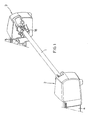
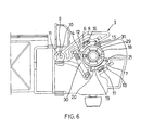
- the present invention is applicable to a copier having a bar 1 which is intended to support the roll of print medium, paper or the like and is coupled between two end heads 2 and 3 which are formed integrally with respective support arms 4 and 5 and are intended to receive the ends of the said bar 1, a braking mechanism being disposed in one of the heads, that is, the head 3 in the embodiment shown, solely an axially acting spring 23 being disposed in the other, opposite head, that is, the head 2.
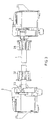
- Springs 30 and 31 keep shoes 6 and 7 applied to a hub 18.
- At least one pair of braking shoes 6 and 7 made of a semi-resilient synthetic material is disposed in the head 3, the first shoe being incorporated in a pivoting arm 8 pivotable on a bar 9 and having a circular-arc-shaped region 10 which is coupled with a fixed hub or cylindrical body 11 and which has, as a geometric axis, the above-mentioned bar 9.
- Both the shoe 6 and the shoe 7 are centred purely axially in respective shoe-holders 12 and 13, the specially shaped ends 14 and 15 being housed in respective housings of matching shape in the shoe-holders.
- the said braking shoes are retained axially by respective tabs 16 and 17 which are formed integrally with the respective shoe holders 12 and 13 at one end and which also have respective teeth for the axial retention of the shoes.
- the shoes have respective central arcuate regions with a smaller radius than that of the hub 18 of the bar 1 to be braked, defining contact regions disposed substantially at the ends in order to bring about the braking effect in two well-defined regions.
- This characteristic which is the same for both shoes 6 and 7, has been shown for the shoe 7 with the central portion 19 with a smaller radius of curvature than that of the hub 18 and with the opposite end portions 20 and 21 which exert the braking effect on the periphery of the hub 18 which has a stainless-steel outer covering or casing 29.
- This arrangement achieves a braking effect directed onto the support bar, the braking effect being exerted at only one of the ends of the bar carrying the roll of print medium, achieving a well controlled friction without noticeable noise, as well as very satisfactory wear characteristics.
- the system can easily be modified to serve other machines with similar characteristics.
- the provision of the braking at only one of the ends of the bar reduces the number of parts of the braking system with a consequent reduction in costs.
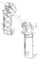
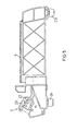
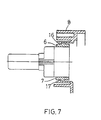
- the head 2 which can be seen with the cap or cover removed in Figure 2 and in an elevational view in Figure 4, has a moulded housing 22 for the opposite end of the bar of the roll of paper to the hub 18, no braking shoes being included at the said end because they are not necessary given the high degree of effectiveness of the braking system of the present invention which permits operation with a single braking system at one end of the bar.
- a spring 23 is incorporated in the said head 2 and acts axially on the end of the bar 1, helping to retain and centre it.
- a desk-top embodiment of the printer preferably has lower pads for bearing on the desk or location in which the printer is placed.
- the drawings show the pads 24 and 25 for the arm 4 as well as the pads 26 and 27 for the arm 5.
- the roll of paper or other print medium is mounted on hubs 32 and 28 coupled close to the ends of the bar 1.
Landscapes
- Engineering & Computer Science (AREA)
- General Engineering & Computer Science (AREA)
- Mechanical Engineering (AREA)
- Unwinding Webs (AREA)
- Handling Of Continuous Sheets Of Paper (AREA)
Claims (13)
- Eine Bremsvorrichtung für eine Trägerwelle (1), zum Tragen einer Papierrolle oder eines Druckmediums in einem Drucker, umfassend eine Nabe (18), welche mit einem Ende der Trägerwelle verbunden ist, mindestens ein Paar Bremsbacken (6, 7) und eine Vorspanneinrichtung (30, 31):wobei die Vorspanneinrichtung (30, 31) so angeordnet ist, daß die Bremsbacken (6, 7) während des Betriebs stetig mit einer im Wesentlichen konstanten Kraft und bei einer im Wesentlichen gleich bleibenden radialen Position im Verhältnis zu der Nabe (18) gegen die Nabe (18) drücken und die Nabe (18) und die Backen (6, 7) jeweils aus unterschiedlichen Materialien bestehen, wobei die Materialien ein Metall und ein synthetisches Material sind, welche ausgewählt sind, um während des Betriebs eine im Wesentlichen gleichmäßige Spannung des Druckmediums für die verschiedenen Phasen der Drehung der Nabe (18) zur Verfügung zu stellen.
- Eine Bremsvorrichtung nach Anspruch 1, wobei lediglich ein Ende der Trägerwelle für das Druckmedium eine wesentliche Bremswirkung aufnimmt.
- Eine Bremsvorrichtung nach Anspruch 1 oder Anspruch 2, wobei die beiden Bremsbacken (6, 7) diametral entgegengesetzt in Bezug auf die Nabe der Trägerwelle liegen, um eine Bremswirkung auf die Trägerwelle auszuüben.
- Eine Bremsvorrichtung nach einem der vorhergehenden Ansprüche, wobei die Bremsbacken des Paares auf entsprechenden Backenhalterungen (12, 13) austauschbar montiert sind.
- Eine Bremsvorrichtung nach einem der vorhergehenden Ansprüche, wobei die Nabe aus Edelstahl hergestellt ist.
- Eine Bremsvorrichtung nach einem der vorhergehenden Ansprüche, wobei das zweite Ende der Trägerwelle für die Druckmediumrolle die Wirkung einer elastischen Einrichtung (23) aufnimmt, welche in axialer Richtung der Trägerwelle wirkt.
- Eine Bremsvorrichtung nach Anspruch 6, wobei die elastische Einrichtung, welche axial auf die Trägerwelle für die Druckmediumrolle einwirkt, eine axiale Feder ist.
- Eine Bremsvorrichtung nach Anspruch 4 oder einem der Ansprüche 5 bis 7, soweit sie davon abhängen, wobei die Vorspanneinrichtung die Bremsbacken im Wesentlichen gegeneinander drückt, im Wesentlichen entlang des Durchmessers der Nabe.
- Eine Bremsvorrichtung nach einem der vorhergehenden Ansprüche, wobei die Vorspanneinrichtung eine oder mehrere Federn umfaßt.
- Eine Bremsvorrichtung nach einem der Ansprüche 4 bis 9, dadurch gekennzeichnet, daß die Bremsbacken koaxial in passend geformten Gehäusen in den Backenhaltern befestigt sind und mittels federnder Laschen (16, 17) festgehalten werden, welche auf die vorderen Enden der jeweiligen Backen mittels entsprechender Haltezähne wirken.
- Eine Bremsvorrichtung nach einem der vorhergehenden Ansprüche, dadurch gekennzeichnet, daß die Bremsbacken aus halbfederndem synthetischen Material hergestellt sind.
- Eine Bremsvorrichtung nach einem der vorhergehenden Ansprüche, dadurch gekennzeichnet, daß die Bremsbacken jeweils Kontaktbereiche (20, 21) mit der Nabe besitzen, wobei sich die Kontaktbereiche nahe an den Enden der Backen befinden und durch einen ausgesparten Bereich (19) in der Backe getrennt sind, der die Nabe nicht berührt.
- Eine Bremsvorrichtung nach Anspruch 1, dadurch gekennzeichnet, daß einer der Backenhalter als Drehbalken (8) gestaltet ist, auf den durch die Vorspanneinrichtung eingewirkt wird.
Priority Applications (2)
| Application Number | Priority Date | Filing Date | Title |
|---|---|---|---|
| EP19970500152 EP0905072B1 (de) | 1997-09-02 | 1997-09-02 | Bremse für eine die Papierrolle tragende Welle im Drucker |
| DE69722402T DE69722402T2 (de) | 1997-09-02 | 1997-09-02 | Bremse für eine die Papierrolle tragende Welle im Drucker |
Applications Claiming Priority (1)
| Application Number | Priority Date | Filing Date | Title |
|---|---|---|---|
| EP19970500152 EP0905072B1 (de) | 1997-09-02 | 1997-09-02 | Bremse für eine die Papierrolle tragende Welle im Drucker |
Publications (2)
| Publication Number | Publication Date |
|---|---|
| EP0905072A1 EP0905072A1 (de) | 1999-03-31 |
| EP0905072B1 true EP0905072B1 (de) | 2003-05-28 |
Family
ID=8230092
Family Applications (1)
| Application Number | Title | Priority Date | Filing Date |
|---|---|---|---|
| EP19970500152 Expired - Lifetime EP0905072B1 (de) | 1997-09-02 | 1997-09-02 | Bremse für eine die Papierrolle tragende Welle im Drucker |
Country Status (2)
| Country | Link |
|---|---|
| EP (1) | EP0905072B1 (de) |
| DE (1) | DE69722402T2 (de) |
Families Citing this family (2)
| Publication number | Priority date | Publication date | Assignee | Title |
|---|---|---|---|---|
| US6478489B2 (en) | 2001-01-31 | 2002-11-12 | Hewlett-Packard Company | Printer rollfeed media tension system with friction ring |
| CN111332036B (zh) * | 2020-04-15 | 2025-05-20 | 厦门汉印股份有限公司 | 一种卷纸打印机 |
Family Cites Families (6)
| Publication number | Priority date | Publication date | Assignee | Title |
|---|---|---|---|---|
| DE1218473B (de) * | 1963-07-18 | 1966-06-08 | Standard Elektrik Lorenz Ag | Verfahren und Vorrichtung zum faltenfreien Transport einer zu Beschriftungszwecken angefeuchteten Papierbahn |
| DE1908270C3 (de) * | 1969-02-19 | 1975-07-10 | Siemens Ag, 1000 Berlin Und 8000 Muenchen | Abwickelvorrichtung für in Rollenform bereitgestellten Papiervorrat, insbesondere für Schnelldrucker |
| DE2207130A1 (de) * | 1972-02-16 | 1973-08-23 | Gerhard Bubenzer | Abspulvorrichtung mit bremse |
| JPS616436A (ja) * | 1984-05-15 | 1986-01-13 | Uedasa Chuzosho:Kk | 氷雪・雨水侵入防止制輪子を有する制動装置 |
| DE8606662U1 (de) * | 1986-03-11 | 1986-05-07 | Nixdorf Computer Ag, 4790 Paderborn | Bremseinrichtung zum Bremsen einer Bandwickelrolle |
| US5562034A (en) * | 1995-07-26 | 1996-10-08 | Intermec Corporation | Media roll braking system for a thermal label printer |
-
1997
- 1997-09-02 EP EP19970500152 patent/EP0905072B1/de not_active Expired - Lifetime
- 1997-09-02 DE DE69722402T patent/DE69722402T2/de not_active Expired - Fee Related
Also Published As
| Publication number | Publication date |
|---|---|
| DE69722402T2 (de) | 2004-05-06 |
| EP0905072A1 (de) | 1999-03-31 |
| DE69722402D1 (de) | 2003-07-03 |
Similar Documents
| Publication | Publication Date | Title |
|---|---|---|
| EP0627948B1 (de) | Rollschuhbremse | |
| US5860496A (en) | Pin guided push-pull caliper | |
| HU216596B (hu) | Irányzáró önbeálló görgő | |
| EP0846637B1 (de) | Förderer | |
| JPH0436076B2 (de) | ||
| EP0905072B1 (de) | Bremse für eine die Papierrolle tragende Welle im Drucker | |
| EP0367706B1 (de) | Nachtränk- und Transferrollen-Anordnung | |
| RU2204523C2 (ru) | Ручная машинка для переноса пленки с несущей ленты на подложку | |
| NL8006066A (nl) | Inrichting voor het aanbrengen van buiteneinddelen in de vorm van kartonschijven aan de uiteinden van gewikkelde papierrollen. | |
| US6729628B2 (en) | Brake for inline skates | |
| US5255763A (en) | Brake cam roller follower bracket | |
| JP4418544B2 (ja) | 輪転印刷機のためのインキつぼ | |
| US5778650A (en) | Device for stopping a spindle of a textile machine driven by a drive belt | |
| US7007884B2 (en) | Roll paper feed device for printing machine | |
| US3774532A (en) | Numberer for printing wheel | |
| JP4970541B2 (ja) | ナンバリングシリンダ上へのナンバリング装置の装着 | |
| US4174142A (en) | Brush mounting for rotary electrical joint | |
| US6053446A (en) | Drag system for accommodating thermal expansion | |
| JPH0971345A (ja) | 圧接ローラ | |
| JPH045627B2 (de) | ||
| GB2242415A (en) | Sheet separator with sheet restraining means. | |
| JPS6141713Y2 (de) | ||
| JP3707717B2 (ja) | オートテンショナ | |
| GB2238525A (en) | Sprung wheel | |
| US5052833A (en) | Self-inking continuous ribbon cartridge system |
Legal Events
| Date | Code | Title | Description |
|---|---|---|---|
| PUAI | Public reference made under article 153(3) epc to a published international application that has entered the european phase |
Free format text: ORIGINAL CODE: 0009012 |
|
| AK | Designated contracting states |
Kind code of ref document: A1 Designated state(s): DE GB |
|
| 17P | Request for examination filed |
Effective date: 19990921 |
|
| AKX | Designation fees paid |
Free format text: DE GB |
|
| RAP1 | Party data changed (applicant data changed or rights of an application transferred) |
Owner name: HEWLETT-PACKARD COMPANY, A DELAWARE CORPORATION |
|
| 17Q | First examination report despatched |
Effective date: 20010529 |
|
| GRAH | Despatch of communication of intention to grant a patent |
Free format text: ORIGINAL CODE: EPIDOS IGRA |
|
| GRAH | Despatch of communication of intention to grant a patent |
Free format text: ORIGINAL CODE: EPIDOS IGRA |
|
| GRAA | (expected) grant |
Free format text: ORIGINAL CODE: 0009210 |
|
| AK | Designated contracting states |
Designated state(s): DE GB |
|
| REG | Reference to a national code |
Ref country code: GB Ref legal event code: FG4D |
|
| REF | Corresponds to: |
Ref document number: 69722402 Country of ref document: DE Date of ref document: 20030703 Kind code of ref document: P |
|
| PLBE | No opposition filed within time limit |
Free format text: ORIGINAL CODE: 0009261 |
|
| STAA | Information on the status of an ep patent application or granted ep patent |
Free format text: STATUS: NO OPPOSITION FILED WITHIN TIME LIMIT |
|
| 26N | No opposition filed |
Effective date: 20040302 |
|
| PGFP | Annual fee paid to national office [announced via postgrant information from national office to epo] |
Ref country code: DE Payment date: 20070228 Year of fee payment: 10 |
|
| PG25 | Lapsed in a contracting state [announced via postgrant information from national office to epo] |
Ref country code: DE Free format text: LAPSE BECAUSE OF NON-PAYMENT OF DUE FEES Effective date: 20080401 |
|
| REG | Reference to a national code |
Ref country code: GB Ref legal event code: 732E Free format text: REGISTERED BETWEEN 20120329 AND 20120404 |
|
| PGFP | Annual fee paid to national office [announced via postgrant information from national office to epo] |
Ref country code: GB Payment date: 20150825 Year of fee payment: 19 |
|
| GBPC | Gb: european patent ceased through non-payment of renewal fee |
Effective date: 20160902 |
|
| PG25 | Lapsed in a contracting state [announced via postgrant information from national office to epo] |
Ref country code: GB Free format text: LAPSE BECAUSE OF NON-PAYMENT OF DUE FEES Effective date: 20160902 |