EP0904988A2 - Eckstossfänger zur Verwendung auf beweglichen und festen Gegenständen - Google Patents
Eckstossfänger zur Verwendung auf beweglichen und festen Gegenständen Download PDFInfo
- Publication number
- EP0904988A2 EP0904988A2 EP98117611A EP98117611A EP0904988A2 EP 0904988 A2 EP0904988 A2 EP 0904988A2 EP 98117611 A EP98117611 A EP 98117611A EP 98117611 A EP98117611 A EP 98117611A EP 0904988 A2 EP0904988 A2 EP 0904988A2
- Authority
- EP
- European Patent Office
- Prior art keywords
- presented
- interiorly
- wall
- exteriorly
- elongate
- Prior art date
- Legal status (The legal status is an assumption and is not a legal conclusion. Google has not performed a legal analysis and makes no representation as to the accuracy of the status listed.)
- Withdrawn
Links
- 238000010008 shearing Methods 0.000 claims abstract description 11
- 239000011162 core material Substances 0.000 claims description 15
- 239000000463 material Substances 0.000 description 9
- 238000010276 construction Methods 0.000 description 4
- 230000001012 protector Effects 0.000 description 3
- 239000002184 metal Substances 0.000 description 2
- 239000007787 solid Substances 0.000 description 2
- 230000003466 anti-cipated effect Effects 0.000 description 1
- 238000013459 approach Methods 0.000 description 1
- 230000015572 biosynthetic process Effects 0.000 description 1
- 239000011152 fibreglass Substances 0.000 description 1
- 230000002452 interceptive effect Effects 0.000 description 1
- 239000004033 plastic Substances 0.000 description 1
- 229920003023 plastic Polymers 0.000 description 1
- 125000000391 vinyl group Chemical group [H]C([*])=C([H])[H] 0.000 description 1
- 229920002554 vinyl polymer Polymers 0.000 description 1
Images

Classifications
-
- E—FIXED CONSTRUCTIONS
- E02—HYDRAULIC ENGINEERING; FOUNDATIONS; SOIL SHIFTING
- E02B—HYDRAULIC ENGINEERING
- E02B3/00—Engineering works in connection with control or use of streams, rivers, coasts, or other marine sites; Sealings or joints for engineering works in general
- E02B3/20—Equipment for shipping on coasts, in harbours or on other fixed marine structures, e.g. bollards
- E02B3/26—Fenders
-
- B—PERFORMING OPERATIONS; TRANSPORTING
- B60—VEHICLES IN GENERAL
- B60R—VEHICLES, VEHICLE FITTINGS, OR VEHICLE PARTS, NOT OTHERWISE PROVIDED FOR
- B60R19/00—Wheel guards; Radiator guards, e.g. grilles; Obstruction removers; Fittings damping bouncing force in collisions
- B60R19/02—Bumpers, i.e. impact receiving or absorbing members for protecting vehicles or fending off blows from other vehicles or objects
- B60R2019/026—Buffers, i.e. bumpers of limited extent
-
- Y—GENERAL TAGGING OF NEW TECHNOLOGICAL DEVELOPMENTS; GENERAL TAGGING OF CROSS-SECTIONAL TECHNOLOGIES SPANNING OVER SEVERAL SECTIONS OF THE IPC; TECHNICAL SUBJECTS COVERED BY FORMER USPC CROSS-REFERENCE ART COLLECTIONS [XRACs] AND DIGESTS
- Y02—TECHNOLOGIES OR APPLICATIONS FOR MITIGATION OR ADAPTATION AGAINST CLIMATE CHANGE
- Y02A—TECHNOLOGIES FOR ADAPTATION TO CLIMATE CHANGE
- Y02A30/00—Adapting or protecting infrastructure or their operation
- Y02A30/30—Adapting or protecting infrastructure or their operation in transportation, e.g. on roads, waterways or railways
Definitions
- This invention relates in general to certain new and useful improvements in corner bumpers used on movable objects for protecting stationary structures against impact by the movable object and, on fixed objects to protect a movable object or, for that matter, the fixed object against impact by another movable object.
- Automotive vehicles such as passenger automotive vehicles, and, for that matter, truck tractors are sometimes equipped with bumpers to preclude damage to a fixed structure, or otherwise, a stationary structure, upon engagement with that fixed or stationary structure, such as a building or a parked vehicle.
- portions of a vehicle are not equipped with bumpers, as for example, the upper portions of a truck and trailer and, particularly, the rear portion of a trailer which may be backed-up toward a fixed building structure. If the trailer should contact that fixed or other stationary structure, damage would result not only to the fixed or stationary structure, but potentially to the trailer, as well.
- corner protectors There have been certain proposed corner protectors, or so-called "corner bumpers".
- the only moderately partially effective corner protector which has been made available is one which is inflatable and uses air as a collapsible medium allowing the corner bumper to absorb the force of an impact.
- This commercially available corner protector comprises a pair of arms or elongate sections which are integrally connected to one another at common ends and includes a top wall to engage the corner of a truck trailer or otherwise the rear portion of a utility truck or a corner of a boat dock. Moreover, the interior of the elongate members is hollow and provided with a means to fill sealed pockets with air, much in the nature of a balloon.
- these commercially available bumpers only have a limited life span and, even though they may be formed of a relatively durable material, they can rupture upon sufficient impact, or otherwise, allowing an escape of the air cushion. In addition, and after a reasonable period of time, they will become brittle and crack, again leading to a lose of the air cushion and thereby become relatively ineffective and incapable of performing their intended function.
- corner bumper which utilizes a plurality of outwardly projecting elements, such as fingers, on the exterior surface thereof and which are designed to either deflect or compress upon engagement with a fixed or stationary structure upon contact.
- outwardly projecting elements are closely spaced apart from one another.
- these outwardly projecting fingers even though formed of a moderately thick and durable rubber material, do not effectively absorb the force of an impact and, frequently, will break off of the bumper, thereby again interfering with its function and operation.
- the present invention relates primarily to a corner bumper adapted for use on movable objects and also on fixed objects.
- the corner bumper can find use on movable objects in the nature of vehicles and which include, for example, truck tractors, truck trailers, single unit trucks and the like.
- the corner bumpers are designed for use on the corners of such movable objects but they are also effective for use on other edge portions of an object.
- The also find effective use on stationary objects to protect the movable object or the stationary object.
- the corner bumper of the invention are also effective for use on fixed objects or other stationary objects as, for example, boat docks, in order to protect a boat against impact.
- stationary structure is used in a broad sense to refer to any structure which may be in a stationary position when engaged by a movable object.
- an airplane is normally a moving object.
- it is temporarily a stationary or a fixed structure since it is parked and non-moving.
- the corner bumper of the invention is unique in that it reduces the possibility of a shearing action on the bumper which might otherwise cause a removal of the corner bumper from a secured position on a utility truck or other vehicle or a fixed object or a movable object.
- the bumper is uniquely designed so that its outer edges are relatively thin. As a result, any impact in the region of an edge of the bumper would likely avoid that edge and engage the greater surface area of the exterior side wall of the bumper, thereby precluding an actual shearing action.
- the exterior side walls of the bumper are actually shaped with a proper taper from the outer edge to the corner portion so that they actually reduce the likelihood of any shearing of the corner bumper from a secured position on a vehicle or other movable object.
- the corner bumper comprises a first elongate section having a first interiorly presented wall and first exteriorly presented wall.
- the bumper also includes a second elongate section connected to an end of the first elongate section and also has a second interiorly presented wall and a second exteriorly presented wall.
- the ends of the elongate sections which are connected together at a corner portion are preferably integrally formed together so that the two elongate sections constitute a single unit.
- the opposite ends, that is the unconnected ends of the elongate sections are generally free ends, but which are tapered to relatively thin edges so as to reduce the possibility of a shearing action, as previously described.
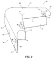
- C designates a corner bumper having a first elongate section 20 and a second elongate section 22.
- Each of the elongate sections 20 and 22 are generally identical in construction and are connected at common ends, preferably at approximately right angles relative to one another, as best shown in Figures 1 and 2 of the drawings. Consequently, portions of the one elongate section 20 will be described in detail, with it being understood that such description is applicable to the generally perpendicularly arranged other elongate section 22.
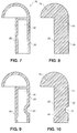
- the elongate 20 generally comprises an interior core 24 preferably formed of a relatively rigid yet compressible plastic or rubber material, such as vinyl, although any of the other previously identified materials could be employed for this purpose.
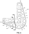
- the core integrally merges into an interiorly presented side wall 26, as shown in Figure 5, and an exteriorly presented side wall 28, as best shown in Figure 4.
- the elongate section 22 has an interiorly presented side wall 30 and an exteriorly presented side wall 32, and the side wall 32 of which extends to a common corner or joinder region 34, as hereinafter described.
- the exteriorly presented wall 32 of the elongate section 22 diverges outwardly from the interiorly presented wall 30, commencing from the relatively thin outer edge 38 almost until the region of the joinder 34. In this way, as the elongate sections increase from the outer ends, they progressively have a thicker cross-section.
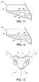
- the outer corner portion 40 where the exterior walls 28 and 32 integrally merge is arcuate in shape as best illustrated in Figures 4 and 5 of the drawings.
- each of the exterior side wall surface 28 and 32 also taper inwardly toward the respective interiorly presented side wall surface 26 and 30, respectively, in the regions of their lower ends 44. In this way, there is, again, a reduced likelihood of causing a shearing action if a force of an impact should engage the corner bumper at any one of the lower edges.
- each of the elongate sections 20 and 22 are also provided with a large number of vertically arranged openings or channels, as best shown in Figures 1 and 5 of the drawings. Some of those openings terminate in the lower corner regions 44 as shown in Figures 1 and 3 of the drawings. Moreover, each of these openings 46 are generally circularly shaped, although other shaped openings could be employed, if desired. Moreover, it can be seen that the regions existing between each of the openings 46 form ribs 48. These ribs 48 are not necessarily of linear side walls, although the openings 46 do effectively form ribs 48 which extend between the respective interiorly presented walls and the exteriorly presented walls.
- the core material is chosen so that it will also have some degree of resiliency.
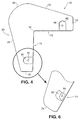
- the region of impact 50 in Figure 10 will generally return to its original shape, as shown in Figure 8, after the force which caused the impact has been removed.
- the grouping of a large number of openings in the region of joinder 34 has also been found to be preferable, since this is the region which typically receives the greatest impact.
- the density of the hole pattern can vary depending upon the materials of construction which are employed and the intended use of the corner bumper.
- the shape of the openings can also vary and are not necessarily limited to circular openings, but they could be triangular, rectangular, etc.
- the elongate sections 20 and 22 are each provided, adjacent their lower ends, with recesses 64 and aligned fastener receiving holes 66, which are sized to receive conventional fasteners, such as sheet metal screws or the like. In this way, the elongate sections can be secured to a movable object such as a truck trailer or a stationary object, such as a boat dock. These recesses and fastener receiving holes are located so that the corner bumpers can be secured to a movable object or a stationary object, or both.
- the corner bumper C is also provided with a top wall 68 which is comprised of a top lip 70 extending inwardly from the elongate section 20 and a top lip 72 extending inwardly from the elongate section 22 and which are again integrally joined in a joinder region 74.
- the top wall 68 may be secured to the elongate sections 20 and 22 or they may be integral therewith.
- the top wall 68 is formed of the same material used in the formation of the elongate sections 20 and 22.
- the lips 70 and 72 are each formed of a generally solid-core material and are not provided with openings in the same manner as the elongate sections 20 and 22. However, it should be understood that, if desired, the lips 70 and 72 could also be provided with holes in the same manner for purposes of collapsing in the event of an impact. However, it has been found that there is typically little likelihood of impact on the upper surface of the top wall 68 and that the material of construction is generally sufficient to compress and absorb the force of any impact.
- the top wall 68 is somewhat hemispherically shaped although it increases from relatively wide transverse ends 76 and 78 to the region of joinder 74.
- the exterior margin of the top wall 68 also conforms to that of the upper margin on the exterior walls 28 and 32 of each of the elongate sections 20 and 22, respectively.
- the lips 70 and 72 are each of a relatively thick crosssection, that is, from exterior wall to interior wall in the region of the joinder 74, and that there is a generally uniform but increasing divergence of the outer margins of the lips 70 and 72 as they progress from the respective ends 76 and 78 to the region of joinder 74.
- the lips 70 and 72 are each provided with recesses 80 and 82, respectively, along their upper surfaces and communicating fastener receiving openings 84 and 86 to receive conventional fasteners, such as sheet metal screws (not shown). Again, and although only two such fastener receiving recesses have been shown, it should be understood that any number of desired recesses can be employed.
- Figure 13 illustrates the corner bumper C used on a movable object such as a truck T.
- the truck T has a pair of side walls 90 and 92 along with a top wall 94.
- the present invention has been largely described in connection with the use of the corner bumper on a movable object and, although that is unique application, the invention is also highly effective for use on fixed objects to protect against impact with a movable object.
- the corner bumper may be designed to protect the fixed object, such as a boat dock, or it may be designed to protect the boat against that impact or both. In either case, the corner bumper is highly effective.
Landscapes
- Engineering & Computer Science (AREA)
- General Engineering & Computer Science (AREA)
- Mechanical Engineering (AREA)
- Ocean & Marine Engineering (AREA)
- Environmental & Geological Engineering (AREA)
- Civil Engineering (AREA)
- Structural Engineering (AREA)
- Vibration Dampers (AREA)
- Building Environments (AREA)
- Vehicle Step Arrangements And Article Storage (AREA)
Applications Claiming Priority (2)
| Application Number | Priority Date | Filing Date | Title |
|---|---|---|---|
| US939045 | 1978-09-01 | ||
| US08/939,045 US6036155A (en) | 1997-09-26 | 1997-09-26 | Corner bumper for use on movable objects |
Publications (2)
| Publication Number | Publication Date |
|---|---|
| EP0904988A2 true EP0904988A2 (de) | 1999-03-31 |
| EP0904988A3 EP0904988A3 (de) | 2001-05-09 |
Family
ID=25472447
Family Applications (1)
| Application Number | Title | Priority Date | Filing Date |
|---|---|---|---|
| EP98117611A Withdrawn EP0904988A3 (de) | 1997-09-26 | 1998-09-17 | Eckstossfänger zur Verwendung auf beweglichen und festen Gegenständen |
Country Status (6)
| Country | Link |
|---|---|
| US (1) | US6036155A (de) |
| EP (1) | EP0904988A3 (de) |
| KR (1) | KR19990029544A (de) |
| CN (1) | CN1215007A (de) |
| CA (1) | CA2248427A1 (de) |
| TW (1) | TW434158B (de) |
Cited By (5)
| Publication number | Priority date | Publication date | Assignee | Title |
|---|---|---|---|---|
| WO2005049453A1 (en) * | 2003-11-18 | 2005-06-02 | Innovation Central Pty Ltd | Resilient protector to protect a structure from an impact |
| EP1565352A4 (de) * | 2002-10-31 | 2007-03-28 | Shape Corp | Eine ecke am ende eines stossfängermittelteils bildender stossfängerhalter |
| AU2004290611B2 (en) * | 2003-11-18 | 2011-01-20 | Innovation Central Pty Ltd | Resilient protector to protect a structure from an impact |
| CN102051864A (zh) * | 2010-12-09 | 2011-05-11 | 同济大学 | 新型消能防撞钢套箱 |
| US9414677B2 (en) | 2013-01-16 | 2016-08-16 | Southwest Agri-Plastics, Inc. | Impact barrier for a storage rack |
Families Citing this family (20)
| Publication number | Priority date | Publication date | Assignee | Title |
|---|---|---|---|---|
| US6378831B1 (en) * | 2000-05-11 | 2002-04-30 | John R Copeland, Jr. | Air-guard corner and edge protector |
| US20080253947A2 (en) * | 2003-05-20 | 2008-10-16 | Phillip Davis | Corner protector for preventing tearing of sterilization wrap wrapped around a sterilization tray |
| US20060130716A1 (en) * | 2003-10-20 | 2006-06-22 | Kent Ashby | Table |
| US20050285003A1 (en) * | 2004-06-28 | 2005-12-29 | Craw Charles M | Elastomeric device that reduces instrument movement |
| WO2007019233A2 (en) * | 2005-08-03 | 2007-02-15 | Quadion Corporation | Surgical tray corner protector |
| USD713060S1 (en) | 2006-06-07 | 2014-09-09 | Sport Systems Unlimited Corp. | Soft caps for dasher board |
| US20070287548A1 (en) | 2006-06-07 | 2007-12-13 | Premier Rinks, Inc. | Soft caps for dasher board assemblies |
| US7793598B2 (en) * | 2007-01-26 | 2010-09-14 | Strobl Jr Frederick P | Plastic panel, particularly for use as production pallet |
| KR100863215B1 (ko) | 2007-05-04 | 2008-10-13 | 정도영 | 모서리 보호대 및 그에 결합되는 캡 |
| US20090200445A1 (en) * | 2008-02-13 | 2009-08-13 | Llewellyn Richard Benn | Inflatable Toddler Bumpers |
| US8721208B2 (en) * | 2008-02-25 | 2014-05-13 | Avery Dennison Corporation | Portable printer and methods |
| TWM344774U (en) * | 2008-07-11 | 2008-11-21 | Fruitshop Internat Corp | Soft protection cover |
| USD707105S1 (en) | 2009-05-15 | 2014-06-17 | Sports Systems Unlimited Corp. | H style divider matrix sleeve |
| US8201796B2 (en) | 2009-08-20 | 2012-06-19 | Rhoost, Llc. | Corner protector |
| USD656007S1 (en) | 2011-01-05 | 2012-03-20 | Aspen Surgical Products, Inc. | Corner protector |
| US9180825B1 (en) * | 2014-09-05 | 2015-11-10 | Karen Jones | Vehicle door protective cushion |
| US10099599B2 (en) | 2015-08-19 | 2018-10-16 | Creative Solutions, Inc. | Cargo net anchor guard |
| USD860058S1 (en) * | 2018-01-31 | 2019-09-17 | Backsaver International, Inc. | Safety bumper for a trailer tailgate |
| US11079798B1 (en) * | 2020-12-21 | 2021-08-03 | Pioneer Square Brands, Inc. | Case for portable electronic computing device |
| US12516560B1 (en) * | 2024-07-03 | 2026-01-06 | Macneil Ip Llc | Wall protector |
Family Cites Families (15)
| Publication number | Priority date | Publication date | Assignee | Title |
|---|---|---|---|---|
| US2685147A (en) * | 1952-01-08 | 1954-08-03 | Colson Corp | Corner bumper |
| USD246625S (en) | 1976-05-21 | 1977-12-13 | Metropolitan Wire Corporation | Corner bumper |
| US4055362A (en) * | 1976-06-18 | 1977-10-25 | Metropolitan Wire Corporation | Bumper assembly for a rolling cart |
| US4072231A (en) * | 1977-02-17 | 1978-02-07 | Helms Hosea W | Corner protector |
| USD260590S (en) | 1979-07-06 | 1981-09-08 | Hobson Haydn H | Corner guard for furniture |
| FR2602653B1 (fr) * | 1986-07-28 | 1989-12-01 | Varlet Marc | Amortisseur de securite pour coin de table ou de meuble |
| US4742916A (en) * | 1987-06-08 | 1988-05-10 | Kord Products Limited | Corner and edge protectors for rectangular articles |
| US4903686A (en) * | 1988-11-09 | 1990-02-27 | Thad Jennings | Outer hearth pad |
| USD302789S (en) | 1988-12-09 | 1989-08-15 | David Levine | Corner pad |
| US5149575A (en) * | 1990-10-17 | 1992-09-22 | Soifer Martin T | Corner edge bumpers |
| US5131669A (en) * | 1991-05-28 | 1992-07-21 | Unarco Industries, Inc. | Bumper assembly with resilient bumper for shopping cart |
| US5233804A (en) * | 1991-06-27 | 1993-08-10 | Miller Donald W | Corner protector assembly and retainer clip therefor |
| USD356946S (en) | 1993-03-04 | 1995-04-04 | Royalox International, Inc. | Corner guard |
| US5639072A (en) * | 1995-08-28 | 1997-06-17 | Mccall; Gary W. | Compressionally elastic plastic bumpers for furniture edges |
| USD412436S (en) | 1997-10-02 | 1999-08-03 | Jones Tsui | Corner bumper |
-
1997
- 1997-09-26 US US08/939,045 patent/US6036155A/en not_active Expired - Lifetime
-
1998
- 1998-09-04 KR KR1019980036500A patent/KR19990029544A/ko not_active Withdrawn
- 1998-09-11 TW TW087115176A patent/TW434158B/zh active
- 1998-09-17 EP EP98117611A patent/EP0904988A3/de not_active Withdrawn
- 1998-09-25 CN CN98120762A patent/CN1215007A/zh active Pending
- 1998-09-25 CA CA002248427A patent/CA2248427A1/en not_active Abandoned
Non-Patent Citations (1)
| Title |
|---|
| None |
Cited By (7)
| Publication number | Priority date | Publication date | Assignee | Title |
|---|---|---|---|---|
| EP1565352A4 (de) * | 2002-10-31 | 2007-03-28 | Shape Corp | Eine ecke am ende eines stossfängermittelteils bildender stossfängerhalter |
| WO2005049453A1 (en) * | 2003-11-18 | 2005-06-02 | Innovation Central Pty Ltd | Resilient protector to protect a structure from an impact |
| US7770861B2 (en) | 2003-11-18 | 2010-08-10 | Innovation Central Pty Ltd | Resilient protector to protect a structure from an impact |
| AU2004290611B2 (en) * | 2003-11-18 | 2011-01-20 | Innovation Central Pty Ltd | Resilient protector to protect a structure from an impact |
| CN102051864A (zh) * | 2010-12-09 | 2011-05-11 | 同济大学 | 新型消能防撞钢套箱 |
| US9414677B2 (en) | 2013-01-16 | 2016-08-16 | Southwest Agri-Plastics, Inc. | Impact barrier for a storage rack |
| US11013328B1 (en) | 2013-01-16 | 2021-05-25 | Southwest Agri-Plastics, Inc. | Impact barrier for a storage unit |
Also Published As
| Publication number | Publication date |
|---|---|
| KR19990029544A (ko) | 1999-04-26 |
| US6036155A (en) | 2000-03-14 |
| EP0904988A3 (de) | 2001-05-09 |
| TW434158B (en) | 2001-05-16 |
| CN1215007A (zh) | 1999-04-28 |
| CA2248427A1 (en) | 1999-03-26 |
Similar Documents
| Publication | Publication Date | Title |
|---|---|---|
| EP0904988A2 (de) | Eckstossfänger zur Verwendung auf beweglichen und festen Gegenständen | |
| US6416094B1 (en) | Energy absorbing bumper | |
| US4225167A (en) | Vehicle bumpers with collapsible parts | |
| US20040016383A1 (en) | Fender with leaf spring | |
| US20060017296A1 (en) | Multi-purpose impact absorbent units | |
| US6832570B2 (en) | Fender with compact spring element | |
| JP4461330B2 (ja) | 車両強制停止装置と該装置を使用した車両強制停止方法 | |
| US6941874B2 (en) | System for preventing the intrusion of a window into a rail vehicle cab in the event of an impact | |
| RU2264310C2 (ru) | Накладка для защиты края поверхности | |
| US3497238A (en) | Splash guards | |
| US5027736A (en) | Elastically deformable bumper system | |
| US4333674A (en) | Vehicle bumpers with collapsible parts | |
| HK1016549A (en) | Corner bumper for use on movable and fixed objects | |
| WO2019226214A1 (en) | Curved quarter fender rock guard | |
| KR200321305Y1 (ko) | 지하차도 입구용 충격흡수장치 | |
| GB2336812A (en) | Bumper arrangement | |
| US20020148177A1 (en) | Loading dock door seal | |
| CN217500096U (zh) | 一种海洋平台用护舷 | |
| US5931248A (en) | Durable roll-stabilizing keel system for hovercraft | |
| JP2518075Y2 (ja) | 防舷材用カバー | |
| EP0896907A1 (de) | Stossfänger | |
| JP4565129B2 (ja) | 道路用分離帯ブロック | |
| KR100491508B1 (ko) | 충격 흡수용 가이드 레일 | |
| CN217997982U (zh) | 一种防撞码头 | |
| JP3270840B2 (ja) | 車両用保安防護体 |
Legal Events
| Date | Code | Title | Description |
|---|---|---|---|
| PUAI | Public reference made under article 153(3) epc to a published international application that has entered the european phase |
Free format text: ORIGINAL CODE: 0009012 |
|
| AK | Designated contracting states |
Kind code of ref document: A2 Designated state(s): AT BE CH CY DE DK ES FI FR GB GR IE IT LI LU MC NL PT SE |
|
| AX | Request for extension of the european patent |
Free format text: AL;LT;LV;MK;RO;SI |
|
| PUAL | Search report despatched |
Free format text: ORIGINAL CODE: 0009013 |
|
| AK | Designated contracting states |
Kind code of ref document: A3 Designated state(s): AT BE CH CY DE DK ES FI FR GB GR IE IT LI LU MC NL PT SE |
|
| AX | Request for extension of the european patent |
Free format text: AL;LT;LV;MK;RO;SI |
|
| STAA | Information on the status of an ep patent application or granted ep patent |
Free format text: STATUS: THE APPLICATION IS DEEMED TO BE WITHDRAWN |
|
| 18D | Application deemed to be withdrawn |
Effective date: 20010331 |
|
| REG | Reference to a national code |
Ref country code: HK Ref legal event code: WD Ref document number: 1016549 Country of ref document: HK |