EP0904981B1 - Procédé et dispositif pour régler la distance d'éclairage d'un phare - Google Patents
Procédé et dispositif pour régler la distance d'éclairage d'un phare Download PDFInfo
- Publication number
- EP0904981B1 EP0904981B1 EP19980114238 EP98114238A EP0904981B1 EP 0904981 B1 EP0904981 B1 EP 0904981B1 EP 19980114238 EP19980114238 EP 19980114238 EP 98114238 A EP98114238 A EP 98114238A EP 0904981 B1 EP0904981 B1 EP 0904981B1
- Authority
- EP
- European Patent Office
- Prior art keywords
- headlamp
- signal
- circuit arrangement
- transistor
- time
- Prior art date
- Legal status (The legal status is an assumption and is not a legal conclusion. Google has not performed a legal analysis and makes no representation as to the accuracy of the status listed.)
- Expired - Lifetime
Links
- 238000000034 method Methods 0.000 title claims description 14
- 239000003990 capacitor Substances 0.000 claims description 21
- 230000000873 masking effect Effects 0.000 claims description 11
- 238000010586 diagram Methods 0.000 description 4
- 230000000694 effects Effects 0.000 description 2
- 230000033001 locomotion Effects 0.000 description 2
- 230000010355 oscillation Effects 0.000 description 2
- 239000000919 ceramic Substances 0.000 description 1
- 239000003985 ceramic capacitor Substances 0.000 description 1
- 230000008878 coupling Effects 0.000 description 1
- 238000010168 coupling process Methods 0.000 description 1
- 238000005859 coupling reaction Methods 0.000 description 1
- 230000007423 decrease Effects 0.000 description 1
- 230000001419 dependent effect Effects 0.000 description 1
- 238000011161 development Methods 0.000 description 1
- 230000018109 developmental process Effects 0.000 description 1
- 238000013021 overheating Methods 0.000 description 1
- 238000005096 rolling process Methods 0.000 description 1
- 239000004065 semiconductor Substances 0.000 description 1
- 230000002123 temporal effect Effects 0.000 description 1
Images

Classifications
-
- B—PERFORMING OPERATIONS; TRANSPORTING
- B60—VEHICLES IN GENERAL
- B60Q—ARRANGEMENT OF SIGNALLING OR LIGHTING DEVICES, THE MOUNTING OR SUPPORTING THEREOF OR CIRCUITS THEREFOR, FOR VEHICLES IN GENERAL
- B60Q1/00—Arrangement of optical signalling or lighting devices, the mounting or supporting thereof or circuits therefor
- B60Q1/02—Arrangement of optical signalling or lighting devices, the mounting or supporting thereof or circuits therefor the devices being primarily intended to illuminate the way ahead or to illuminate other areas of way or environments
- B60Q1/04—Arrangement of optical signalling or lighting devices, the mounting or supporting thereof or circuits therefor the devices being primarily intended to illuminate the way ahead or to illuminate other areas of way or environments the devices being headlights
- B60Q1/06—Arrangement of optical signalling or lighting devices, the mounting or supporting thereof or circuits therefor the devices being primarily intended to illuminate the way ahead or to illuminate other areas of way or environments the devices being headlights adjustable, e.g. remotely-controlled from inside vehicle
- B60Q1/08—Arrangement of optical signalling or lighting devices, the mounting or supporting thereof or circuits therefor the devices being primarily intended to illuminate the way ahead or to illuminate other areas of way or environments the devices being headlights adjustable, e.g. remotely-controlled from inside vehicle automatically
- B60Q1/10—Arrangement of optical signalling or lighting devices, the mounting or supporting thereof or circuits therefor the devices being primarily intended to illuminate the way ahead or to illuminate other areas of way or environments the devices being headlights adjustable, e.g. remotely-controlled from inside vehicle automatically due to vehicle inclination, e.g. due to load distribution
- B60Q1/115—Arrangement of optical signalling or lighting devices, the mounting or supporting thereof or circuits therefor the devices being primarily intended to illuminate the way ahead or to illuminate other areas of way or environments the devices being headlights adjustable, e.g. remotely-controlled from inside vehicle automatically due to vehicle inclination, e.g. due to load distribution by electric means
Definitions
- the invention relates to a method for headlamp leveling of a headlamp according to the preamble of claim 1 and a circuit arrangement according to the preamble of claim 7.
- the headlamp leveling of the headlights is provided regularly. A headlamp leveling is therefore necessary so that the headlights are adjusted depending on the load condition of the car so that oncoming traffic is not dazzled.
- stepless headlamp levelers or switchable headlamp levelers are common.
- FIG. 5 A known circuit arrangement for a headlamp leveling of a motor vehicle headlight is shown in FIG 5.
- the circuit is constructed as follows.
- a setpoint generator 14 is connected in the form of a transmitter potentiometer.
- This setpoint generator 14 is located in the area of the dashboard A of the vehicle.
- the supply lines B are shown for simplicity sake by the series connection of a resistor 16 with a downstream coil 18 intentionallyschaltsentlich.
- the headlamp leveler C has a drive motor 12 for height and / or tilt adjustment of the headlamp 10. The adjustment is indicated schematically by the arrow P.
- the headlamp leveler C has a control device IC with an input-side comparison stage 20 and an output-side driver stage 24, to which the drive motor 12 is connected. Between the comparator 20, which is regularly hysteresis, and the driver stage 24, a logic unit 22 is connected. For voltage supply of the comparison stage 20, the logic unit 22 and the driver stage 24, these are connected with supply lines to the supplied via the series connection of the resistor 16 and the coil 18 supply voltage V S and to reference potential.
- the comparison stage 20 is connected with its one input terminal to the center tap of the setpoint generator 14 and receives from there a desired signal V 14 . At the other input terminal, the comparison stage 20 receives the actual signal V FB and forms at its output hysteresis a differential voltage .DELTA.V.
- the setpoint generator on the dashboard A allows the driver of the car the individual adjustment of the headlight position. Due to the necessary mechanical coupling of the motor 12 and the actual value transmitter 28 with the headlight 10, the headlamp leveler C is accommodated directly on the headlight 10.
- the drive motor 12 is driven by the driver stage 24, which is preferably a full bridge circuit. Depending on the position of the setpoint generator 14 of the headlight 10 is more or less up or dimmed, so the inclination angle can be adjusted.
- the actual value 28 is used as an angle sensor.
- This provides the actual signal V FB and is mechanically connected to the drive motor 12 and z. B. connected via a worm drive with the pitch mechanism of the headlamp 10.
- the signal V 14 supplied from the reference value generator 14 is compared in the comparator 20 with the signal V FB. Depending on the differential voltage V, the drive motor 12 rotates as long and changes the signal V FB until the difference signal .DELTA.V becomes zero.
- the invention has the aim of providing a method and a circuit arrangement for headlamp leveling of a headlight, which makes the use of an electrolytic capacitor with high capacity unnecessary and therefore is small-scale to realize.
- the invention essentially provides an additional device which blocks the result of an actual / desired comparison of the control loop for a predetermined time each time the drive motor is started and thus blocks it.
- the output signal of the comparison stage within the control device remains without effect for this time.
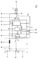
- the decisive difference from the circuit arrangement of FIG. 5 is the circuit arrangement of FIG. 1 in that in the control device IC, preferably as an integrated circuit Circuit is executed, a blanking device 30 is seated, which is coupled to the logic unit 22 in a manner to be explained.
- the blanking device 30 receives a signal START from the logic unit 22, processes this signal and forwards to the logic unit 22 a signal BLANK.
- the masking device 30 is connected to reference potential via a capacitor 40, which is arranged outside the control device IC.
- the capacitor 26 is now formed not as an electrolytic capacitor, but as a capacitor with a relatively small capacity.
- the capacitor 26 also serves as a filter capacitor, but may be reduced to a few 100 nF.
- the blanking device 30 ensures that the output signal of the comparator 20 remains without effect for a predetermined period of time and is thus hidden.
- the circuit operates again without the blanking device 30 continues to influence.
- the blanking time can be adapted individually to the respective application with a ceramic capacitor of relatively small capacity (cf, see FIG. 3).
- the capacitor 26 is still required to limit the rate of voltage change (dV S / dt). Too high a voltage change rate (“slew rate”) has repercussions from the driver stage 24 on the logic unit 22 and the comparison stage 20 result. Such repercussions occur in particular when the control device IC is monolithically integrated in a semiconductor body.
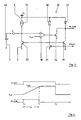
- FIG. 2 With each other four timing diagrams of voltage and current waveforms in temporal relation to each other shown one below the other.
- the uppermost curve shows the voltage signal V 14 which, starting from a higher value at time a, is gradually reduced to a lower value by corresponding actuation of the setpoint generator 14 (see FIG. At time c, this lower value is reached.
- V HY is the hysteresis voltage of the comparison stage 20.
- the signal V 14 reaches the lower hysteresis value of the comparator 20.
- the drive motor 12 starts.
- the motor current IM jumps at the time b to the high stall current I STALL , then with the mechanical time constant to the nominal current I NEN fall .
- V S drops abruptly at time b.
- the actual value signal V FB breaks according to the dashed line in the upper signal diagram at time b and drops significantly below the desired signal V 14 .
- the drive motor 12 would in this case be stopped and controlled backwards since V FB ⁇ (V 14 -1/2 V HY ).
- the masking device 30 ensures that immediately after the start of the drive motor 12, ie at time b, the output signal of the comparator 20 is suppressed for a predetermined period of time.
- the predetermined period of time is chosen so that in any case after the expiry of the period V FB > V 14 .
- the blanking time t A is chosen so large that its end is slightly after the time c. As shown in the top timing diagram of Fig. 2, that is, the signal V FB jumps suddenly under V 14 at time b, and then gradually increase again. After the blanking time t A , the signal V FB decreases until the point in time at which the drive motor 12 is switched off.
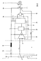
- FIG. 3 shows an exemplary embodiment of the masking device 30 of FIG. 1.
- the circuit has the already described capacitor 40, which may for example have a capacitance value of 47 nF and is connected to one terminal to the reference potential terminal 3 and with its other terminal to a terminal of the control device.
- This terminal is designated by the reference character K and within the masking device 30 with the non-inverting input of a comparator 38 in combination.
- the inverting input of the comparator 38 is in contact with a reference voltage V REF .
- the terminal K is also connected via a current source 31 to the supply voltage terminal 5 for the supply voltage V S.
- the terminal K is additionally connected via the load path of a bipolar transistor 32 to the reference potential terminal 3.
- the output terminal of the comparator 38 is connected to the control terminal of a second transistor 34 in connection.
- the load path of this second transistor 34 is located between the reference potential terminal 3 and a terminal on which the signal BLANK can be tapped.
- This terminal is connected via a resistor 37 to the supply voltage terminal 5 in combination.
- this terminal is connected via the load path of a third transistor 35 to the reference potential terminal 3.
- the control terminal of this third transistor 35 is connected to the control terminal of the first transistor 32 in connection and via the load path of a fourth transistor 33 to the reference potential terminal 3.
- the connection point of the two control terminals of the transistors 32, 35 is further connected via a resistor 36 to the supply voltage terminal 5.
- the control terminal of the fourth transistor is connected to a terminal for the signal START.
- the mentioned resistors 36, 37 may also be replaced by current sources.
- this masking device 30 will become apparent in connection with the waveforms of FIG. If the difference V 14 -V FB (compare FIG. 1) is greater than the switching hysteresis of the comparator 20, the signal START is generated, which clamps the bases of the transistors 32 and 35 via the transistor 33. As a result, the charging process of the capacitor 40 is started, whereby the voltage V 40 dropping across it increases. With the beginning of the signal START also the signal BLANK starts at the time t 0 . If the voltage V 40 reaches the reference voltage V ref , the signal BLANK is set by the transistor 34 back to low level "Low". The time span t 1 -t 0 is the fade time t A.
- the logic unit 22 of the control device IC ensures that the output signal of the comparison stage 20 is hidden. If the signal V 14 is equal to the signal V FB , which is the case at time t 2 , the signal START is reset and the capacitor 40 is discharged via the transistor 32.
- the circuit can not necessarily be used only for headlamp leveling of headlamps. Rather, the inventive method and the proposed circuit arrangement also finds useful wherever it is important that a motor without unwanted reciprocating motion must start. Such motors are commonly referred to as servomotors.
Landscapes
- Engineering & Computer Science (AREA)
- Mechanical Engineering (AREA)
- Lighting Device Outwards From Vehicle And Optical Signal (AREA)
Claims (15)
- Procédé pour régler la distance d'éclairage d'un projecteur (10), selon lequel un moteur d'entraînement (12) couplé mécaniquement au projecteur (10) est entraîné pour régler le projecteur (10), en fonction d'un signal de réglage obtenu par une comparaison valeur réelle/valeur de consigne
caractérisé en ce qu'
après chaque démarrage du moteur d'entraînement (12) le résultat de la comparaison valeur réelle/valeur de consigne est ignoré et donc masqué pendant une durée prédéterminée (tA). - Procédé selon la revendication 1,
caractérisé en ce que
le signal de réglage est déduit en tant que signal différentiel entre un signal de consigne (V14) venant d'un dispositif de réglage (14) à actionner manuellement et un signal réel (VFB) correspondant à la position actuelle du projecteur (10). - Procédé selon la revendication 1 ou 2,
caractérisé en ce que
le signal de réglage est soumis à une hystérésis. - Procédé selon l'une des revendications 1 à 3,
caractérisé en ce que
la durée prédéterminée (tA) est réglable. - Procédé selon l'une des revendications 1 à 4,
caractérisé en ce que
le début (t0) de la durée (tA) est déterminé par une grandeur prédéterminée du signal différentiel, et la fin (t1) de la durée (tA) est atteinte lorsqu'un condensateur (40) a été chargé à une tension de référence (Vref) prédéterminée. - Procédé selon la revendication 5,
caractérisé en ce qu'
un signal de remise à l'état initial pour un nouveau début (0) de la durée (tA) est produit lorsque le signal différentiel est au moins approximativement égal à égale à 0. - Dispositif pour régler la distance d'éclairage d'un projecteur ayant les caractéristiques suivantes :- un moteur d'entraînement (12) pour régler le projecteur (10) ;- un générateur de valeur réelle (28) couplé au projecteur (10) pour former un signal de valeur réelle (VFB) déterminant pour la position actuelle du projecteur (10) ;- un consignateur (14) pour former un signal de valeur de consigne (V14) déterminant pour une position de consigne du projecteur (10) ;- un dispositif de commande (IC) entraînant le moteur d'entraînement (12) en fonction d'un signal différentiel formé à partir du signal de valeur de consigne (V14) et du signal de valeur réelle (VFB),caractérisé par
une autre caractéristique :- un dispositif de masquage (30) prévu dans le dispositif de commande (IC), masque, après chaque démarrage du moteur d'entraînement (12), le signal différentiel pour une durée prédéterminée (tA). - Dispositif selon la revendication 7,
caractérisé en ce que
le dispositif de commande (IC) comporte côté entrée un étage de comparaison (20) et côté sortie un étage d'attaque (24), ainsi qu'une unité logique (22) située entre l'étage de comparaison (20) et l'étage d'attaque (24). - Dispositif selon la revendication 8,
caractérisé en ce que
le générateur de valeur réelle (28) et/ou le consignateur (14) sont formés par des potentiomètres, la prise médiane ou les prises médianes du ou des potentiomètres étant couplées avec l'étage de comparaison (20) du dispositif de commande (IC). - Dispositif selon l'une des revendications 7 à 9,
caractérisé en ce que
le dispositif de masquage (30) comporte un condensateur (40) déterminant pour la durée (tA) et un comparateur (38), et le comparateur (38) peut recevoir côté entrée une tension de référence (Vef) d'une part et est connecté au condensateur (40) d'autre part. - Dispositif selon l'une des revendications 7 à 10,
caractérisé en ce que
le dispositif de masquage (30) présente le montage en série d'un montage en série d'une source de courant (31), monté entre une borne de tension d'alimentation (1) et une borne à potentiel de référence (3), et le trajet sous charge d'une transistor (32), le condensateur (40) est monté entre la borne à potentiel de référence (3) et la prise médiane du montage en série de la source de courant (31) et du transistor (32), la prise médiane est reliée à une première source d'entrée du comparateur (38), une autre borne d'entrée du comparateur (38) peut être couplée à la tension de référence (Vref), la sortie du comparateur (38) est reliée au raccordement de commande d'un deuxième transistor (34), le trajet sous charge de ce deuxième transistor (34) est relié entre la borne à potentiel de référence (3) et une borne de sortie d'un signal de sortie (BLANK) du dispositif de masquage (30), cette borne de sortie est reliée par l'intermédiaire d'une résistance (37) à la borne de tension d'alimentation (1) et par l'intermédiaire du trajet sous charge d'un troisième transistor (35) à la borne à potentiel de référence (3), le raccordement de commande de ce troisième transistor (35) est relié au raccordement de commande du premier transistor (32) et connecté par l'intermédiaire du trajet sous charge d'un quatrième transistor (33) à la borne à potentiel de référence (3) et par l'intermédiaire d'une autre résistance (36) à la borne de tension d'alimentation (1), et le raccordement de commande du quatrième transistor (33) est relié à une borne d'entrée d'un signal d'entrée (START) du dispositif de masquage (30). - Dispositif selon la revendication 11,
caractérisé en ce qu'
au moins une des résistances (36, 37) est réalisée par des sources de courant. - Dispositif selon l'une des revendications 7 à 12,
caractérisé en ce que
la dispositif de commande IC est un circuit intégré. - Dispositif selon l'une des revendications 7 à 13,
caractérisé en ce que
l'étage de comparaison (20) présente une hystérésis de commutation. - Dispositif selon l'une des revendications 7 à 14,
caractérisé en ce que
le projecteur (10) est un phare d'automobile.
Applications Claiming Priority (2)
| Application Number | Priority Date | Filing Date | Title |
|---|---|---|---|
| DE1997143260 DE19743260C2 (de) | 1997-09-30 | 1997-09-30 | Verfahren und Schaltungsanordnung zur Leuchtweitenregulierung eines Scheinwerfers |
| DE19743260 | 1997-09-30 |
Publications (3)
| Publication Number | Publication Date |
|---|---|
| EP0904981A2 EP0904981A2 (fr) | 1999-03-31 |
| EP0904981A3 EP0904981A3 (fr) | 2003-04-16 |
| EP0904981B1 true EP0904981B1 (fr) | 2007-12-12 |
Family
ID=7844190
Family Applications (1)
| Application Number | Title | Priority Date | Filing Date |
|---|---|---|---|
| EP19980114238 Expired - Lifetime EP0904981B1 (fr) | 1997-09-30 | 1998-07-28 | Procédé et dispositif pour régler la distance d'éclairage d'un phare |
Country Status (2)
| Country | Link |
|---|---|
| EP (1) | EP0904981B1 (fr) |
| DE (2) | DE19743260C2 (fr) |
Families Citing this family (1)
| Publication number | Priority date | Publication date | Assignee | Title |
|---|---|---|---|---|
| JP2001322484A (ja) * | 2000-05-12 | 2001-11-20 | Koito Mfg Co Ltd | 車輌用灯具の光軸調整装置用モータ制御回路 |
Family Cites Families (4)
| Publication number | Priority date | Publication date | Assignee | Title |
|---|---|---|---|---|
| FR2190265A5 (fr) * | 1972-06-23 | 1974-01-25 | Jaeger | |
| DE2846602A1 (de) * | 1978-10-26 | 1980-05-08 | Bosch Gmbh Robert | Einrichtung fuer die selbsttaetige berichtigung der scheinwerferneigung von fahrzeugen |
| DE3827983C1 (fr) * | 1988-08-18 | 1990-02-01 | Hella Kg Hueck & Co, 4780 Lippstadt, De | |
| DE4024915A1 (de) * | 1990-08-06 | 1992-02-13 | Hella Kg Hueck & Co | Verfahren und einrichtung zur regelung der leuchtweite eines kraftfahrzeugs |
-
1997
- 1997-09-30 DE DE1997143260 patent/DE19743260C2/de not_active Expired - Fee Related
-
1998
- 1998-07-28 EP EP19980114238 patent/EP0904981B1/fr not_active Expired - Lifetime
- 1998-07-28 DE DE59814136T patent/DE59814136D1/de not_active Expired - Lifetime
Also Published As
| Publication number | Publication date |
|---|---|
| EP0904981A3 (fr) | 2003-04-16 |
| DE59814136D1 (de) | 2008-01-24 |
| DE19743260C2 (de) | 1999-10-21 |
| EP0904981A2 (fr) | 1999-03-31 |
| DE19743260A1 (de) | 1999-04-08 |
Similar Documents
| Publication | Publication Date | Title |
|---|---|---|
| DE60015052T2 (de) | Halbleiter-Leistungswandlungsvorrichtung | |
| EP0543826B1 (fr) | Procede et dispositif d'excitation d'un consommateur electomagnetique | |
| DE2716476A1 (de) | Niveauregeleinrichtung fuer kraftfahrzeuge | |
| DE2705320C2 (de) | Fahrzeugscheinwerfer-Steuerschaltung | |
| EP0072406A2 (fr) | Dispositif pour allumer ou éteindre les feux automatiquement | |
| DE3507130A1 (de) | Treiberstromkreis fuer eine magnetspule | |
| DE3233536A1 (de) | Einrichtung zum getakteten regeln eines eine spule durchfliessenden stromes | |
| EP0904981B1 (fr) | Procédé et dispositif pour régler la distance d'éclairage d'un phare | |
| DE19708115C1 (de) | Verfahren zur Ansteuerung eines Sensors mit Offsetregelung | |
| DE69108187T2 (de) | Regelvorrichtung für die von einem Wechselstromgenerator abgegebene Batteriespannung. | |
| DE3924805A1 (de) | Gleichspannungswandler | |
| EP0545111A2 (fr) | Dispositif de réglage de l'inclinaison de phares de véhicule | |
| WO2005083251A1 (fr) | Procede et dispositif pour actionner un organe de reglage capacitif | |
| EP0098460B1 (fr) | Dispositif de régulation pour organe électrique de manoeuvre | |
| EP1504317B1 (fr) | Circuit d alimentation en courant | |
| WO2006119751A2 (fr) | Procede et dispositif de commande electrique d'une soupape au moyen d'un element de fermeture mecanique | |
| EP0197035A1 (fr) | Montage de circuits pour le fonctionnement de lampes a decharge a basse tension a ultraviolet ou a substance fluorescente | |
| DE10202279A1 (de) | Steuerschaltung für einen Aktor | |
| EP1625663A2 (fr) | Circuit integre et procede de programmation d'un circuit integre | |
| DE3335200A1 (de) | Spannungsversorgungseinrichtung fuer kraftfahrzeuge | |
| DE102009047714A1 (de) | Schaltungsanordnung und Verfahren zum Betreiben mindestens einer Entladungslampe | |
| EP2807056B1 (fr) | Procédé et système de commande d'au moins un élément de déclenchement d'un moyen de protection des personnes | |
| EP2440022A2 (fr) | Commutation et procédé de commande d'une lampe | |
| DE10040078C2 (de) | Einrichtung zur lastabhängigen Zusatzverstellung von Scheinwerfern für Kraftfahrzeuge | |
| DE4223660C2 (de) | Vorrichtung zum Einstellen des Lichtstrahlwinkels eines Fahrzeugscheinwerfers |
Legal Events
| Date | Code | Title | Description |
|---|---|---|---|
| PUAI | Public reference made under article 153(3) epc to a published international application that has entered the european phase |
Free format text: ORIGINAL CODE: 0009012 |
|
| AK | Designated contracting states |
Kind code of ref document: A2 Designated state(s): AT BE CH CY DE DK ES FI FR GB GR IE IT LI LU MC NL PT SE |
|
| AX | Request for extension of the european patent |
Free format text: AL;LT;LV;MK;RO;SI |
|
| RAP1 | Party data changed (applicant data changed or rights of an application transferred) |
Owner name: INFINEON TECHNOLOGIES AG |
|
| PUAL | Search report despatched |
Free format text: ORIGINAL CODE: 0009013 |
|
| AK | Designated contracting states |
Designated state(s): AT BE CH CY DE DK ES FI FR GB GR IE IT LI LU MC NL PT SE |
|
| AX | Request for extension of the european patent |
Extension state: AL LT LV MK RO SI |
|
| RIC1 | Information provided on ipc code assigned before grant |
Ipc: 7B 60Q 1/076 A |
|
| 17P | Request for examination filed |
Effective date: 20030625 |
|
| AKX | Designation fees paid |
Designated state(s): DE FR GB IE IT |
|
| GRAP | Despatch of communication of intention to grant a patent |
Free format text: ORIGINAL CODE: EPIDOSNIGR1 |
|
| GRAS | Grant fee paid |
Free format text: ORIGINAL CODE: EPIDOSNIGR3 |
|
| GRAA | (expected) grant |
Free format text: ORIGINAL CODE: 0009210 |
|
| AK | Designated contracting states |
Kind code of ref document: B1 Designated state(s): DE FR GB IE IT |
|
| REG | Reference to a national code |
Ref country code: GB Ref legal event code: FG4D Free format text: NOT ENGLISH |
|
| REG | Reference to a national code |
Ref country code: IE Ref legal event code: FG4D Free format text: LANGUAGE OF EP DOCUMENT: GERMAN |
|
| REF | Corresponds to: |
Ref document number: 59814136 Country of ref document: DE Date of ref document: 20080124 Kind code of ref document: P |
|
| GBT | Gb: translation of ep patent filed (gb section 77(6)(a)/1977) |
Effective date: 20080227 |
|
| ET | Fr: translation filed | ||
| PLBE | No opposition filed within time limit |
Free format text: ORIGINAL CODE: 0009261 |
|
| STAA | Information on the status of an ep patent application or granted ep patent |
Free format text: STATUS: NO OPPOSITION FILED WITHIN TIME LIMIT |
|
| 26N | No opposition filed |
Effective date: 20080915 |
|
| REG | Reference to a national code |
Ref country code: FR Ref legal event code: PLFP Year of fee payment: 19 |
|
| PGFP | Annual fee paid to national office [announced via postgrant information from national office to epo] |
Ref country code: DE Payment date: 20160920 Year of fee payment: 19 |
|
| REG | Reference to a national code |
Ref country code: FR Ref legal event code: PLFP Year of fee payment: 20 |
|
| PGFP | Annual fee paid to national office [announced via postgrant information from national office to epo] |
Ref country code: IT Payment date: 20170728 Year of fee payment: 20 Ref country code: GB Payment date: 20170719 Year of fee payment: 20 Ref country code: FR Payment date: 20170724 Year of fee payment: 20 |
|
| PGFP | Annual fee paid to national office [announced via postgrant information from national office to epo] |
Ref country code: IE Payment date: 20170727 Year of fee payment: 20 |
|
| REG | Reference to a national code |
Ref country code: DE Ref legal event code: R119 Ref document number: 59814136 Country of ref document: DE |
|
| PG25 | Lapsed in a contracting state [announced via postgrant information from national office to epo] |
Ref country code: DE Free format text: LAPSE BECAUSE OF NON-PAYMENT OF DUE FEES Effective date: 20180201 |
|
| REG | Reference to a national code |
Ref country code: GB Ref legal event code: PE20 Expiry date: 20180727 Ref country code: IE Ref legal event code: MK9A |
|
| PG25 | Lapsed in a contracting state [announced via postgrant information from national office to epo] |
Ref country code: IE Free format text: LAPSE BECAUSE OF EXPIRATION OF PROTECTION Effective date: 20180728 |
|
| PG25 | Lapsed in a contracting state [announced via postgrant information from national office to epo] |
Ref country code: GB Free format text: LAPSE BECAUSE OF EXPIRATION OF PROTECTION Effective date: 20180727 |