EP0904965A2 - Rolldachanordnung an einem Fahrzeug - Google Patents
Rolldachanordnung an einem Fahrzeug Download PDFInfo
- Publication number
- EP0904965A2 EP0904965A2 EP98114787A EP98114787A EP0904965A2 EP 0904965 A2 EP0904965 A2 EP 0904965A2 EP 98114787 A EP98114787 A EP 98114787A EP 98114787 A EP98114787 A EP 98114787A EP 0904965 A2 EP0904965 A2 EP 0904965A2
- Authority
- EP
- European Patent Office
- Prior art keywords
- roller
- roof
- vehicle
- elements
- arrangement according
- Prior art date
- Legal status (The legal status is an assumption and is not a legal conclusion. Google has not performed a legal analysis and makes no representation as to the accuracy of the status listed.)
- Withdrawn
Links
- 230000005540 biological transmission Effects 0.000 claims abstract description 9
- 238000005096 rolling process Methods 0.000 claims description 13
- 230000007246 mechanism Effects 0.000 claims description 6
- 230000000977 initiatory effect Effects 0.000 claims description 3
- 230000008878 coupling Effects 0.000 description 5
- 238000010168 coupling process Methods 0.000 description 5
- 238000005859 coupling reaction Methods 0.000 description 5
- 238000004804 winding Methods 0.000 description 3
- 230000009471 action Effects 0.000 description 2
- 230000002349 favourable effect Effects 0.000 description 2
- 238000005253 cladding Methods 0.000 description 1
- 230000006835 compression Effects 0.000 description 1
- 238000007906 compression Methods 0.000 description 1
- 238000010276 construction Methods 0.000 description 1
- 238000006073 displacement reaction Methods 0.000 description 1
- 239000004744 fabric Substances 0.000 description 1
- 239000012634 fragment Substances 0.000 description 1
- 239000000446 fuel Substances 0.000 description 1
- 230000001960 triggered effect Effects 0.000 description 1
Images


Classifications
-
- B—PERFORMING OPERATIONS; TRANSPORTING
- B60—VEHICLES IN GENERAL
- B60J—WINDOWS, WINDSCREENS, NON-FIXED ROOFS, DOORS, OR SIMILAR DEVICES FOR VEHICLES; REMOVABLE EXTERNAL PROTECTIVE COVERINGS SPECIALLY ADAPTED FOR VEHICLES
- B60J7/00—Non-fixed roofs; Roofs with movable panels, e.g. rotary sunroofs
- B60J7/08—Non-fixed roofs; Roofs with movable panels, e.g. rotary sunroofs of non-sliding type, i.e. movable or removable roofs or panels, e.g. let-down tops or roofs capable of being easily detached or of assuming a collapsed or inoperative position
- B60J7/085—Non-fixed roofs; Roofs with movable panels, e.g. rotary sunroofs of non-sliding type, i.e. movable or removable roofs or panels, e.g. let-down tops or roofs capable of being easily detached or of assuming a collapsed or inoperative position winding up, e.g. for utility vehicles
Definitions
- the invention relates to a rolling roof arrangement on a vehicle, in particular a passenger car, wherein a plurality of vehicle roof elements which are arranged one behind the other and are connected to one another in an articulated manner, starting from a position covering a roof opening, can be rolled up onto a roll provided at the end, which roll is designed with a view to the rolling up of the roof elements increasing roll diameter is adjustable in height.
- a spoiler box forming part of the vehicle roof and covering the roller towards the outside can also be height-adjustable in view of the roller diameter that increases as the roof elements roll up.
- Rolling roofs for vehicles are known in different embodiments like, for example, the first two writings have shown, however, despite some inherent advantages in particular not yet implemented on passenger cars. Much more are in addition to sunroofs with a rigid cover part essentially only the so-called fabric folding roofs realized. One reason for this may be the problem in connection with the placement of the roller roof in the open Condition-taking role, which is then a relatively large one Has diameter.
- the roller preferably on its Rotate axis
- attack the spoiler box elements of a gearbox This gearbox is actuated or started by a suitable one Actuator, which can be designed in different ways. It is essential that the role and / or the spoiler box no longer through the roller roof itself, i.e. through the vehicle roof elements wound on the roll, but are positioned differently by an independent gear.
- actuating device actuating the transmission
- either a separate, arbitrarily designed servomotor can be provided for this, or the rotational movement of the roller or the translational movement of the vehicle roof elements can be used to actuate the transmission.
- This embodiment too, in which the height adjustment of the roller and / or the spoiler box is initiated via elements of the transmission by the rotational movement of the roller or the translational movement of the vehicle roof elements, is intended to fall under the term of the adjusting device.
- - as well as in general - coupling gears, link or cam gears, screw gears, cable gears, as well as suitable gear combinations can be used.
- the height adjustment of the spoiler box is preferred via, for example, as Pantograph geared intermediate gear to the height adjustment the role coupled after between the most favorable positions a clear functional relationship between these two components consists.
- the pantograph guidance of the pantograph gear arranged longitudinally displaceably in a rocker, which in turn is pivotable and thus height adjustable, and which carries the role over its axis of rotation.
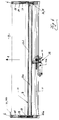
- the reference numeral 23 denotes a roll on which a not shown Canopy of a vehicle can be rolled up.
- This roller roof consists of a plurality of one behind the other in the vehicle longitudinal direction arranged, articulated vehicle roof elements and can, for example, as shown in the prior art mentioned at the beginning be constructed.
- roller roof can be moved in the direction of the vehicle's longitudinal axis, so that sensibly, the axis of rotation 23a of the roller 23 transverse to the longitudinal axis of the vehicle 1 runs, i.e. in the illustration in FIGS. 1, 2 perpendicular to Drawing level.
- This spoiler box 26 consists of a spoiler cover 26a and Box side walls 26b and acts as a housing or cladding for the Roller 23 including its actuating mechanism and for that of the present Mechanism underlying the invention.
- FIGS. 1 and 2 show the state in which the roller roof is completely unwound from the roller 23, while in FIG. 2 the outer circumference of the fully wound roller roof is shown and is designated by the reference number 2. Since the roller roof cannot be completely accommodated on the roller 23 when it is in the position shown in FIG. 1, it is necessary to lift the roller 23 when winding up the roller roof, ie to adjust the height according to the direction of the arrow 3, and thus for example in to bring the position shown in Fig. 2.
- roller 23 and the spoiler box 26 can also have intermediate positions between the two shown in Figures 1, 2 Take extreme positions if only part of the roller roof, i.e. just some of the one behind the other and articulated Vehicle roof elements is / are wound on the roll 23.
- the height of the roller 23 and the spoiler box 26 is adjusted with Help of a gearbox designated in its entirety with 4.
- the Height adjustment of the spoiler box 26 makes sense about one in his Set of 5 intermediate gear to the height adjustment the roller 23 coupled, such that when initiated by the transmission 4 Height adjustment of the roller 23 simultaneously through the intermediate gear 5 the spoiler box 26 is adjusted in height.
- Axis of rotation 23a is mounted in at least one rocker 25.
- Embodiment is one at the two ends of the roller 23 Swing arm 25 is provided so that the two arms 25 each in Vehicle longitudinal direction 1 extending left and right of the Roof opening or generally with respect to the vehicle.
- the two rockers 25 are articulated with their first (in Fig. 1, 2 left-hand) end in a pivot bearing 6 on the vehicle body, such that the second (right-hand) end of each rocker 25 in or against the direction of arrow 3 around it Swivel bearing 6 is pivotable. With this second (right-hand) end, the two rockers 25, which are connected to one another in this area by a so-called rocker spindle nut 37, are supported on a substantially vertically standing threaded spindle 36.
- the threaded spindle 36 is rotatable about its longitudinal axis 36a attached to the vehicle body in a manner explained briefly later.
- On the thread of the threaded spindle 36 with its matching counter thread screwed swing arm nut 37 is as can be seen about an elongated, transverse to the vehicle longitudinal axis 1 and thus component aligned parallel to the roller axis of rotation 23a, which with its ends in the end receiving openings 25a of the rockers 25 is stored.
- this is - as already mentioned - coupled to the height adjustment of the roller 23, specifically via the intermediate gear designated 5 in its entirety, which is designed here as a pantograph gear.
- Components of this pantograph or intermediate gear 5 are a pantograph guide 29 to which an adjusting lever 30 and a support lever 31 are articulated.
- Another element of this intermediate gear 5 is / are the rocker (s) 25, after - as can be seen - the pantograph guide 29 is guided in the rocker rocker 25 which is longitudinally displaceable in or against the direction of the arrow 7.
- the support lever 31 is connected in an articulated manner to the body of the vehicle with its end facing away from the pantograph guide 29, specifically to a so-called roof frame module 24.
- the actuating lever 30 is connected in an articulated manner to the spoiler case 26 with its end facing away from the pantograph guide 29, specifically here to a nose, not shown, which projects from the inside of the spoiler cover 26a.
- both the spoiler box 26 and the rocker 25 are pivotably articulated in the pivot bearing 6, but this is only a measure for reducing the construction and assembly work.
- this is however not required.
- the height adjustment of the roller 23 and / or the spoiler box 26 can of course also be carried out differently than shown here, for example by means of a suitable translational displacement.
- pantograph gear functioning here as an intermediate gear 5 concerns
- its dimensions are chosen so that the Angle between the rocker 25 and the connecting line between them Swivel bearing 6 and the bearing point of the support lever 31 on the roof frame module 24 in a ratio of 1: 1 to the angle between the rocker 25 and the connecting line between their pivot bearing 6 and the bearing point of the control lever 30 is transmitted to the spoiler box 26, however Alternatively, an under- or translation can also be provided here.
- a separate actuator 32 is provided for this, for example can be designed as a suitably controllable electric motor.
- the output shaft of this electric motor can be directly on the threaded spindle 36 be flanged, but it is also a coupling via a suitable one Gearbox, such as a cable pull possible.
- the entire system i.e. the gear 4 and the intermediate gear 5 braced, so that the creation from rattling noises is avoided.
- the spring force line of action and the points of attack of the spring can be varied, for example by the abutment 28 not fixed with respect to the swing arm 25, but fixed to the body becomes.
- suitable damper systems in the overall system be introduced.
- Threaded spindle 36 to be replaced by elastic bearing elements.
- the threaded spindle can 36 directly on the actuator designed for example as an electric motor 32 or flanged to an output shaft of the same, not specified besides, it is also possible between this Actuator 32 and the threaded spindle 36 a torque transmitting Compensating coupling 35 (e.g. a rubber element, a bellows coupling or a universal joint).
- a direct Flange can also be provided that the swing spindle nut 37 with respect to the rocker (s) 25 both rotationally as well is translationally movable.
- FIG. 4 shows the arrangement of the in its Set with 32 designated actuator, which in addition to an electric motor 32a has a deflection drive 32b.
- the electric motor 32a with its output shaft, not specified, transversely to the longitudinal direction of the vehicle 1 aligned so that the deflection drive 32b its rotational movement on the essentially vertically aligned threaded spindle 36 transmits.
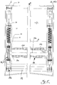
- Fig. 4 in which the vehicle longitudinal direction 1 through the in the middle of the vehicle extending arrow is shown, as well as in Fig. 5, in which the edge regions of the spoiler box 26 and in particular the intermediate gear 5 are enlarged are shown, you can also see the detailed structure of the Roll 23.
- This consists of a roller inner part connected to the rockers 25 23b and an outer roller part 23c rotatably mounted thereon.
- These two roller parts 23b, 23c are each circular cylindrical and concentric to each other and to the axis of rotation 23a in its entirety arranged with 23 designated role.
- a clock spring 23d is provided between the two parts of the roller 23b, 23c, the central axis of which with Axis of rotation 23a coincides and its first end on the inner roller part 23b is attached, while the second end of the inside of the roller outer part 23c is attached.
Landscapes
- Engineering & Computer Science (AREA)
- Mechanical Engineering (AREA)
- Body Structure For Vehicles (AREA)
Abstract
Description
Zum technischen Umfeld wird neben der DE 196 10 751 C1 oder der DE 34 20 641 A1 insbesondere auf die nicht vorveröffentlichte deutsche Patentanmeldung 196 16 971 verwiesen.
Die Lösung dieser Aufgabe ist gekennzeichnet durch ein die Höhenverstellung der Rolle und/oder des Spoilerkastens initiierendes Getriebe. Vorteilhafte Aus- und Weiterbildungen sind Inhalt der Unteransprüche.
Dabei - sowie generell - können als Getriebe Koppelgetriebe, Kulissen- bzw. Kurvengetriebe, Schraubengetriebe, Seilgetriebe, sowie geeignete Getriebekombinationen zum Einsatz kommen.
- Fig. 1
- einen Längsschnitt einer erfindungsgemäßen Rolldach-Anordnung ( = Schnitt B-B aus Fig. 4) mit der Rolle und dem Spolilerkasten im abgesenkten Zustand,
- Fig. 2
- eine analoge Darstellung mit der Rolle und dem Spoilerkasten im angehobenen Zustand
- Fig. 3
- den Schnitt A-A aus Fig. 1,
- Fig. 4
- die Ansicht X aus Fig. 3, sowie
- Fig. 5
- eine in den Randbereichen vergrößerte Darstellung von Fig. 4, wobei der mittlere Bereich ausgeschnitten wurde.
Nachdem das Rolldach nicht komplett auf der Rolle 23 untergebracht werden kann, wenn sich diese in der in Fig. 1 dargestellten Position befindet, ist es erforderlich, die Rolle 23 beim Aufwickeln des Rolldaches anzuheben, d.h. gemäß Pfeilrichtung 3 höhenzuverstellen, und somit bspw. in die in Fig. 2 dargestellte Position zu bringen.
Mit diesem zweiten (rechtsseitigen) Ende stützen sich die beiden Schwingen 25, die in diesem Bereich über eine sog. Schwingenspindelmutter 37 miteinander verbunden sind, auf einer im wesentlichen vertikal stehenden Gewindespindel 36 ab.
Nachdem hier zwei Schwingen 25 vorgesehen sind, sind selbstverständlich auch zwei parallel arbeitende Pantografengetriebe bzw. Zwischengetriebe 5 vorgesehen, so daß sowohl linksseitig als auch rechtsseitig der Dachöffnung des Fahrzeuges jeweils ein Paar von Hebeln 30, 31 vorhanden sind.
Im übrigen sind auf jeder Fahrzeugseite zwei Stützhebel 31 vorgesehen, wie Fig. 3 zeigt, jedoch ist dies für die beschriebene, erfindungsgemäße Funktion nicht erforderlich.
Der Stellhebel 30 ist mit seinem der Pantografenführung 29 abgewandten Ende gelenkig am Spoilerkasten 26 angebunden, und zwar hier an einer von der Innenseite des Spoilerdeckels 26a abragenden, nicht näher bezeichneten Nase.
Ebenfalls im Zusammenhang hiermit sei darauf hingewiesen, daß die Höhenverstellung der Rolle 23 und/oder des Spoilerkastens 26 selbstverständlich auch andersartig als hier gezeigt erfolgen kann, so bspw. durch geeignete translatorische Verschiebung.
- 1
- Fahrzeug-Längsrichtung
- 2
- Umfang des auf 23 aufgewickelten Rolldaches
- 3
- Pfeilrichtung: Höhenverstellung von 23 und 26
- 4
- Getriebe (in seiner Gesamtheit), bestehend aus 25, 36 und 37
- 5
- Zwischengetriebe in Gesamtheit, bestehend aus 25, 29, 30, 31
- 6
- Schwenklager
- 7
- Pfeilrichtung: Verschiebung von 29 in 25
- 8
- Fahrzeugdach
- 9
- Dachausschnitt zur Aufnahme von 26
- 10
- Dichtung an 9
- 23
- Rolle zum Aufwickeln des Rolldaches
- 23a
- Drehachse von 23
- 23b
- Rolleninnenteil
- 23c
- Rollenaußenteil
- 23d
- Wickelfeder
- 24
- Dachrahmenmodul
- 25
- Schwinge
- 25a
- Aufnahmeöffnung in 25 für 37
- 26
- Spoilerkasten
- 26a
- Spoilerdeckel
- 26b
- Kastenseitenwand
- 27
- Federelement
- 28
- Widerlager
- 29
- Pantografenführung
- 30
- Stellhebel
- 31
- Stützhebel
- 32
- Stellantrieb
- 32a
- Elektromotor
- 32b
- Umlenktrieb
- 33
- karosseriefeste Zapfen
- 34
- Pendellager
- 35
- Ausgleichskupplung
- 36
- Gewindespindel
- 36a
- Längsachse von 36
- 37
- Schwingenspindelmutter
Claims (12)
- Rolldach-Anordnung an einem Fahrzeug, insbesondere Personenkraftwagen, wobei mehrere hintereinander angeordnete, gelenkig miteinander verbundene Fahrzeugdach-Elemente ausgehend von einer eine Dachöffnung abdeckenden Position auf eine endseitig vorgesehene Rolle (23) aufrollbar sind, welche im Hinblick auf den durch das Aufrollen der Dachelemente zunehmenden Rollendurchmesser höhenverstellbar ist,
gekennzeichnet durch ein die Höhenverstellung der Rolle (23) initiierendes Getriebe (4). - Rolldach-Anordnung an einem Fahrzeug, insbesondere Personenkraftwagen, wobei mehrere hintereinander angeordnete, gelenkig miteinander verbundene Fahrzeugdach-Elemente ausgehend von einer eine Dachöffnung abdeckenden Position auf eine endseitig vorgesehene Rolle (23) aufrollbar sind und wobei ein einen Bestandteil des Fahrzeugdaches (8) bildender und die Rolle (23) nach außen hin abdeckender Spoilerkasten (26) im Hinblick auf den durch das Aufrollen der Dachelemente zunehmenden Rollendurchmesser höhenverstellbar ist,
gekennzeichnet durch ein die Höhenverstellung des Spoilerkastens (26) initiierendes Getriebe (4, 5). - Rolldach-Anordnung nach Anspruch 1 und 2,
dadurch gekennzeichnet, daß die Höhenverstellung des Spoilerkastens (26) über ein Zwischengetriebe (5) an die Höhenverstellung der Rolle (23) gekoppelt ist. - Rolldach-Anordnung nach Anspruch 1,
dadurch gekennzeichnet, daß die Rolle (23) mit ihrer Drehachse (23a) in zumindest einer verschwenkbar an der Fahrzeug-Karosserie befestigten Schwinge (25) gelagert ist, welche durch Elemente des Getriebes (4) gezielt verschwenkt wird. - Rolldach-Anordnung nach Anspruch 3 und 4,
dadurch gekennzeichnet, daß die Schwinge (25) Bestandteil des als Pantografengetriebe ausgebildeten Zwischengetriebes (5) ist, wozu in der Schwinge (25) längsverschiebbar die Pantografenführung (29) angeordnet ist, an der ein mit der Fahrzeug-Karosserie verbundener Stützhebel (31) sowie ein mit dem Spoilerkasten (26) verbundener Stellhebel (30) angelenkt sind. - Rolldach-Anordnung nach Anspruch 5,
dadurch gekennzeichnet, daß die Pantografenführung (29) an einem eine Höherverstellung des Spoilerkastens (26) unterstützenden Federelement (27) abgestützt ist. - Rolldach-Anordnung nach einem der vorangegangenen Ansprüche,
dadurch gekennzeichnet, daß die Höhenverstellung der Rolle (23) und/ oder des Spoilerkastens (26) über Elemente des Getriebes (4, 5) durch die Rotationsbewegung der Rolle (23) oder durch die Translationsbewegung der Fahrzeugdach-Elemente initiiert wird. - Rolldach-Anordnung nach Anspruch 7,
dadurch gekennzeichnet, daß Elemente des Getriebes (4, 5) ein an der Rolle (23) befestigtes Zahnrad sowie eine mit diesem kämmende geeignet befestigte Zahnstange sind. - Rolldach-Anordnung nach einem der Ansprüche 1 - 6,
dadurch gekennzeichnet, daß die Höhenverstellung der Rolle (23) und/ oder des Spoilerkastens (26) über Elemente des Getriebes (4, 5) durch einen separaten Stellantrieb (32) erfolgt. - Rolldach-Anordnung nach einem der vorangegangenen Ansprüche,
dadurch gekennzeichnet, daß Elemente des Getriebes (4) eine im wesentlichen vertikal ausgerichtete um ihre Längsachse (36a) in Rotation versetzbare Gewindespindel (36) sowie eine auf dieser geführte und an der Schwinge (25) befestigte Schwingenspindelmutter (37) sind. - Rolldach-Anordnung nach Anspruch 10,
dadurch gekennzeichnet, daß die Gewindespindel (36) an der Fahrzeug-Karosserie sowie die Schwingenspindelmutter (37) an der Schwinge (25) jeweils um eine zur Drehachse (23a) der Rolle (23) parallele Achse zumindest geringfügig verschwenkbar gelagert sind. - Rolldach-Anordnung nach einem der vorangegangenen Ansprüche,
dadurch gekennzeichnet, daß die Gewindespindel (36) fest am Stellantrieb (32) angeflanscht und die Schwingenspindelmutter (37) gegenüber der Schwinge (25) rotatorisch und translatorisch bewegbar ist.
Applications Claiming Priority (2)
| Application Number | Priority Date | Filing Date | Title |
|---|---|---|---|
| DE19743108 | 1997-09-30 | ||
| DE1997143108 DE19743108A1 (de) | 1997-09-30 | 1997-09-30 | Rolldach-Anordnung an einem Fahrzeug |
Publications (2)
| Publication Number | Publication Date |
|---|---|
| EP0904965A2 true EP0904965A2 (de) | 1999-03-31 |
| EP0904965A3 EP0904965A3 (de) | 2000-10-18 |
Family
ID=7844087
Family Applications (1)
| Application Number | Title | Priority Date | Filing Date |
|---|---|---|---|
| EP98114787A Withdrawn EP0904965A3 (de) | 1997-09-30 | 1998-08-06 | Rolldachanordnung an einem Fahrzeug |
Country Status (2)
| Country | Link |
|---|---|
| EP (1) | EP0904965A3 (de) |
| DE (1) | DE19743108A1 (de) |
Cited By (1)
| Publication number | Priority date | Publication date | Assignee | Title |
|---|---|---|---|---|
| DE102008020535A1 (de) * | 2008-04-24 | 2009-10-29 | GM Global Technology Operations, Inc., Detroit | Kraftfahrzeugkarosserie |
Families Citing this family (3)
| Publication number | Priority date | Publication date | Assignee | Title |
|---|---|---|---|---|
| DE20112267U1 (de) * | 2001-07-25 | 2002-12-05 | Inalfa Industries B.V., Venray | Kupplungsmechanismus und damit versehene öffnungsfähige Dachkonstruktion für ein Fahrzeug |
| DE102008018440A1 (de) * | 2008-04-08 | 2009-10-15 | Vogelgesang Ag | Kraftfahrzeug mit einer Fahrzeugtragstruktur |
| DE102008023235A1 (de) * | 2008-05-10 | 2009-11-12 | Wilhelm Karmann Gmbh | Fahrzeug mit einem Rollverdeck |
Citations (3)
| Publication number | Priority date | Publication date | Assignee | Title |
|---|---|---|---|---|
| DE3420641A1 (de) | 1984-06-02 | 1985-12-12 | Abdolnasser 7000 Stuttgart Hamid | Cabrioletverdeck fuer kraftfahrzeuge insbesondere pkw, lkw, bus, wohnwagen und boote mit zu- und aufrollbarem dach |
| DE19610751C1 (de) | 1996-03-19 | 1997-04-24 | Daimler Benz Ag | Fahrzeugverdeck |
| DE19616971A1 (de) | 1996-04-27 | 1997-10-30 | Bayerische Motoren Werke Ag | Kraftfahrzeug mit einer Dachöffnung |
Family Cites Families (2)
| Publication number | Priority date | Publication date | Assignee | Title |
|---|---|---|---|---|
| DE371334C (de) * | 1920-08-04 | 1923-03-14 | Desiderio Stapler Dr | Rollverdeck, insbesondere fuer Kraftfahrzeuge |
| FR2738620B1 (fr) * | 1995-09-13 | 1997-10-31 | Peugeot | Piece en matiere plastique destinee a couvrir une surface, notamment d'un vehicule automobile |
-
1997
- 1997-09-30 DE DE1997143108 patent/DE19743108A1/de not_active Withdrawn
-
1998
- 1998-08-06 EP EP98114787A patent/EP0904965A3/de not_active Withdrawn
Patent Citations (3)
| Publication number | Priority date | Publication date | Assignee | Title |
|---|---|---|---|---|
| DE3420641A1 (de) | 1984-06-02 | 1985-12-12 | Abdolnasser 7000 Stuttgart Hamid | Cabrioletverdeck fuer kraftfahrzeuge insbesondere pkw, lkw, bus, wohnwagen und boote mit zu- und aufrollbarem dach |
| DE19610751C1 (de) | 1996-03-19 | 1997-04-24 | Daimler Benz Ag | Fahrzeugverdeck |
| DE19616971A1 (de) | 1996-04-27 | 1997-10-30 | Bayerische Motoren Werke Ag | Kraftfahrzeug mit einer Dachöffnung |
Cited By (1)
| Publication number | Priority date | Publication date | Assignee | Title |
|---|---|---|---|---|
| DE102008020535A1 (de) * | 2008-04-24 | 2009-10-29 | GM Global Technology Operations, Inc., Detroit | Kraftfahrzeugkarosserie |
Also Published As
| Publication number | Publication date |
|---|---|
| DE19743108A1 (de) | 1999-04-01 |
| EP0904965A3 (de) | 2000-10-18 |
Similar Documents
| Publication | Publication Date | Title |
|---|---|---|
| DE10114938B4 (de) | Vorrichtung zum Betätigen einer Automobil-Schwenktüre | |
| DE102020209607B4 (de) | Verschlussanordnung zum Verschließen einer Tankmulde einer Karosserie eines Kraftfahrzeugs | |
| DE4218507C2 (de) | Fensterstellglied | |
| DE19532567C1 (de) | Verdeck für ein Fahrzeug, insbesondere Personenkraftwagen | |
| EP2318631B1 (de) | Kraftfahrzeug mit mechanismus zum bewegen einer klappe oder tür | |
| EP1506115B1 (de) | Kraftunterstützungsmodul zur bereitstellung einer lastabhängigen unterstützungskraft | |
| DE102007013517B4 (de) | Betätigungsvorrichtung für ein bewegliches Verkleidungselement, insbesondere Gestängeklappe, und Cabrioletfahrzeug mit einem solchen Verkleidungselement oder einer solchen Gestängeklappe | |
| DE3518868A1 (de) | Motorisierte betaetigung fuer eine ankoppelvorrichtung, wie z.b. kupplung, regelgetriebe, bremse oder dergl. | |
| DE19860229C2 (de) | Griffanordnung für ein bewegliches Karosserieteil eines Kraftfahrzeugs | |
| EP1740426A1 (de) | Rollosystem für ein fahrzeugdach | |
| DE10041498A1 (de) | Schließeinrichtung für eine Fahrzeugtür | |
| EP0716004A1 (de) | Schwenkschiebetür für Fahrzeuge zur Personenbeförderung | |
| DE19539848C2 (de) | Rollo, insbesondere für Kraftfahrzeuge | |
| DE19912893C2 (de) | Cabrio-Fahrzeug mit einem Verdeck | |
| EP1990223B1 (de) | Verdeck eines Cabriolet-Fahrzeugs | |
| DE4331078A1 (de) | Vorrichtung zur Bewegung einer Schwenkschiebetür für Fahrzeuge zur Personenbeförderung, insbesondere Schienenfahrzeuge | |
| EP0904965A2 (de) | Rolldachanordnung an einem Fahrzeug | |
| EP1004738A2 (de) | Schiebetür mit Schienenführung und einer Verriegelungsvorrichtung | |
| DE1605887C3 (de) | Gelenkanordnung für Fahrzeughauben | |
| DE10131052B4 (de) | Abdeckklappe für ein Fahrzeug | |
| EP0980777A2 (de) | Mehrteiliger Schiebehimmel für ein Schiebedachsystem eines Personenkraftwagens | |
| DE102005047297B3 (de) | Antriebsvorrichtung für einen Verdeckkastendeckel eines Kraftfahrzeugs | |
| DE102020114594A1 (de) | Verstelleinrichtung zum Verstellen eines Windschilds | |
| DE19717993A1 (de) | Vorrichtung zum automatischen Öffnen und/oder Schließen und/oder zum Dämpfen eines Flügels einer Tür, eines Fensters o. dgl. | |
| DE102010004963B4 (de) | Antriebseinrichtung für verstellbare Funktionseinheiten eines Cabriolets |
Legal Events
| Date | Code | Title | Description |
|---|---|---|---|
| PUAI | Public reference made under article 153(3) epc to a published international application that has entered the european phase |
Free format text: ORIGINAL CODE: 0009012 |
|
| AK | Designated contracting states |
Kind code of ref document: A2 Designated state(s): DE ES FR GB IT |
|
| AX | Request for extension of the european patent |
Free format text: AL;LT;LV;MK;RO;SI |
|
| PUAL | Search report despatched |
Free format text: ORIGINAL CODE: 0009013 |
|
| AK | Designated contracting states |
Kind code of ref document: A3 Designated state(s): AT BE CH CY DE DK ES FI FR GB GR IE IT LI LU MC NL PT SE |
|
| AX | Request for extension of the european patent |
Free format text: AL;LT;LV;MK;RO;SI |
|
| RIC1 | Information provided on ipc code assigned before grant |
Free format text: 7B 60J 7/08 A, 7B 60J 7/06 B |
|
| 17P | Request for examination filed |
Effective date: 20010405 |
|
| AKX | Designation fees paid |
Free format text: DE ES FR GB IT |
|
| STAA | Information on the status of an ep patent application or granted ep patent |
Free format text: STATUS: THE APPLICATION IS DEEMED TO BE WITHDRAWN |
|
| 18D | Application deemed to be withdrawn |
Effective date: 20020301 |